

Sony XTL-W7000 Service Manual

XTL-W7000
SERVICE MANUAL
Ver. 1.0 2004.12
• This set includes the TV antenna (VCA-119).
SPECIFICATIONS
Monitor section
Display type Wide LCD colour monitor
Picture size 7 in.; 154 × 87 mm, 180 mm
System TFT active matrix
Number of pixel
TV tuner section
Television system
Colour system
Channel converge
NTSC system only:
PAL system only:
CCIR VHF: 2 - 12 CH
CHINA VHF: 1 - 12 CH
UK/HKG (Hong Kong) VHF: –
ITALY VHF: A - H2 CH
NEWZEALAND VHF: 1 - 11 CH
AUSTRALIA VHF: 0 - 12 CH
(W × H, diagonally)
336,960 pixels
M system (NTSC)/
B, G, I, D, K system (PAL)
TV: NTSC (NTSC system)/PAL
(PAL system)
VIDEO: NTSC/PAL (Compatible)
VHF: 2 - 13 CH
UHF: 14 - 69 CH
UHF: 21 - 69 CH
UHF: 13 - 57 CH
UHF: 21 - 69 CH
UHF: 21 - 69 CH
UHF: 21 - 69 CH
UHF: 28 - 69 CH
E Model
Model Name Using Similar Mechanism NEW
Open/Close Mechanism Type DB-M01
General
Power requirements
12 V DC, from car battery (negative
ground)
Outputs Video/Audio (Sony BUS
compatible, 1)
Sony BUS (1)
Inputs Video/Audio (Sony BUS
compatible, 2)
Composite (either commercially
available navigation system or
back camera can be connected, 1)
Sony BUS (1)
TV antenna (1)
Speaker type 20 × 40 mm (monaural)
Dimensions with monitor retracted
Approx. 178 × 50 × 190.5 mm
(W × H × D)
Current drain Approx. 2 A
Mass Approx. 1.9 kg
Supplied accessories
Card remote commander RM-X701
(1) (incl. 1 lithium battery)
RCA interconnects (Audio L/R × 1,
Video × 1)
TV antenna VCA-119 (left/right) (1)
Parts for installation and
connections (1 set)
Installation/Connections manual (1)
Operating Instructions (1)
Design and specifications are subject to
change without notice.
9-879-218-01
2004L05-1
© 2004.12
MOBILE COLOR TV
Sony Corporation
e Vehicle Company
Published by Sony Engineering Corporation

XTL-W7000
TABLE OF CONTENTS
1. SERVICING NOTE.................................................. 3
2. GENERAL ................................................................... 4
3. DISASSEMBLY
3-1. Disassembly Flow ........................................................... 11
3-2. Front Panel Assy.............................................................. 12
3-3. Case (Lower) Block......................................................... 12
3-4. Partition ........................................................................... 13
3-5. Bracket (Slider) ............................................................... 14
3-6. SLIDER Board ................................................................ 15
3-7. Bracket (Motor) Assy ...................................................... 15
3-8. Bracket (Motor S) Assy ................................................... 16
3-9. Monitor Block ................................................................. 16
3-10. Gear (1), Gear (4) ............................................................ 17
3-11. Mechanism Complete Assy (DB-M01)........................... 17
3-12. Liquid Crystal Display (LCD1)....................................... 18
3-13. MAIN Board.................................................................... 18
4. TEST MODE.............................................................. 19
5. ELECTRICAL ADJUSTMENTS......................... 22
6. DIAGRAMS
6-1. Block Diagram – VIDEO, AUDIO Section – .................. 24
6-2. Block Diagram – LCD, MOTOR Section – .................... 25
6-3. Block Diagram
– CONTROL, POWER SUPPLY Section – .................... 26
6-4. Printed Wiring Board – MAIN Section (1/2) – ............... 28
6-5. Printed Wiring Board – MAIN Section (2/2) – ............... 29
6-6. Schematic Diagram – MAIN Section (1/3) –.................. 30
6-7. Schematic Diagram – MAIN Section (2/3) –.................. 31
6-8. Schematic Diagram – MAIN Section (3/3) –.................. 32
6-9. Printed Wiring Boards – FRONT PANEL Section –....... 33
6-10. Schematic Diagram – FRONT PANEL Section – ........... 33
6-11. Printed Wiring Boards – SLIDER Section – ................... 34
6-12. Schematic Diagram – SLIDER Section – ....................... 35
6-13. Printed Wiring Board – MONITOR Section (1/2) – ....... 36
6-14. Printed Wiring Board – MONITOR Section (2/2) – ....... 37
6-15. Schematic Diagram – MONITOR Section (1/2) – .......... 38
6-16. Schematic Diagram – MONITOR Section (2/2) – .......... 39
6-17. Printed Wiring Board – KEY Section – .......................... 40
6-18. Schematic Diagram – KEY Section – ............................. 40
7. EXPLODED VIEWS
7-1. MAIN Board Section....................................................... 55
7-2. Front Panel Section ......................................................... 56
7-3. Chassis (Main) Section.................................................... 57
7-4. Monitor Section ............................................................... 58
7-5. Open/close Mechanism Deck Section ............................. 59
8. ELECTRICAL PARTS LIST................................ 60
Notes on chip component replacement
• Never reuse a disconnected chip component.
• Notice that the minus side of a tantalum capacitor may be
damaged by heat.
Flexible Circuit Board Repairing
• Keep the temperature of the soldering iron around 270 ˚C
during repairing.
• Do not touch the soldering iron on the same conductor of the
circuit board (within 3 times).
• Be careful not to apply force on the conductor when soldering
or unsoldering.
2
UNLEADED SOLDER
Boards requiring use of unleaded solder are printed with the leadfree mark (LF) indicating the solder contains no lead.
(Caution: Some printed circuit boards may not come printed with
the lead free mark due to their particular size)
: LEAD FREE MARK
Unleaded solder has the following characteristics.
• Unleaded solder melts at a temperature about 40 °C higher
than ordinary solder.
Ordinary soldering irons can be used but the iron tip has to be
applied to the solder joint for a slightly longer time.
Soldering irons using a temperature regulator should be set to
about 350 °C.
Caution: The printed pattern (copper foil) may peel away if
the heated tip is applied for too long, so be careful!
• Strong viscosity
Unleaded solder is more viscou-s (sticky, less prone to flow)
than ordinary solder so use caution not to let solder bridges
occur such as on IC pins, etc.
• Usable with ordinary solder
It is best to use only unleaded solder but unleaded solder may
also be added to ordinary solder.

SECTION 1
7
gear(1 S)
6
stopper washer
(2.6 × 4.5)
1
two screws
(M2)
5
bracket (slider)
3
Rotate the worm gear in the direction of arrow B.
for pulling the monitor block.
8
Pull the monitor block.
Note: Don't touch except the gray portion of worm gear.
A
B
2
Open the bracket (slider)
in the direction of arrow A.
4
SERVICING NOTE
JIG ON REPAIRING
When repairing this set, etc., connect the extension cable as the figure shown below.
extension cable (32P) (J-2502-093-1)
(MONITOR board (CN101)-SLIDER board (CN2))
SLIDER board
(CN2)
MONITOR board
(CN101)
XTL-W7000
extension cable (50P) (J-2502-092-1)
(MAIN board (CN1851)-SLIDER board (CN1))
SLIDER board
(CN1)
HOW TO PULL OUT MONITOR BLOCK IN CASE ELECTRICITY DOES NOT CIRCULATE
When monitor block does not open by fault, pull out monitor block in the following procedures.
MAIN board
(CN1851)
3

XTL-W7000
Main unit
Monitor closed
SECTION 2
GENERAL
Location of Controls
1
This section is extracted from
instruction manual.
3
4
2
1 VIDEO 1 IN jacks (VIDEO, AUDIO (L/R))
2 CUSTOM button
3 TILT button
Monitor opened
5
4 OPEN/CLOSE button
5 Reset button
1
2
1 TV/VIDEO button
2 VOL +/– buttons
3
3 SEEK +/– buttons
4 ANGLE button
4
8
4

Card remote commander
The unit can be operated with the card remote commander.
MUTING
CH+
ENTER
CH–
TV/VIDEO
SEEK+
1
2
3
4
5
OFF
MENU
SEEK–
BACK
WIDE DSPL
PICTURE
XTL-W7000
8
9
q;
qa
qs
6
123
456
7
1 OFF button
2 MENU button
3 V/v CH +/– buttons
4 BACK button
5 WIDE button
6 PICTURE button
7 Number buttons
Tips
• See “Replacing the lithium battery” for details on how to replace the battery.
• If an optional Master-unit is connected using Sony BUS system, function of some of the buttons will change as
follows:
- The TV/VIDEO button will function as a NAVI button (when “NAVI/CAMERA” is set to “NAVI”).
- The OFF button will turn off the monitor.
- The SEEK –/+ and the Number buttons will be invalid.
789
10 11 12
8 MUTING button
Turning off the sound temporarily.
When you press the button, the sound is turned off
and “MUTING” appears in the display.
To restore the sound, press the button again
(or VOL +).
9 TV/VIDEO button
0 ENTER button
qa B/b SEEK –/+ buttons
qs DSPL button
qd VOL +/– buttons
VOL
qd
9
5

XTL-W7000
Connection Example
For details, see the section “1 Car Systems Connections” (pages 8 - 10). Be sure to refer also to the
documentation for all other components in the system.
System configuration
Mobile Colour TV XTL-W7000
Connection of separately available accessories
Items except the main unit and the connection box are optionally available.
Connecting without Sony BUS system
Car antenna for radio
Mobile Colour TV XTL-W7000
Video Camera (optional)
VIDEO1 IN
Sony BUS DVD Master-unit
*1
(optional)
Sony VCD Master-unit
(optional)
*1 Sony BUS DVD Master-unit will come in 2005.
*2 In case of other manufacture’s Master-units, audio signal is reproduced through FM modulator.
To output the audio of other manufacture’s Master-units using the RF modulator
If you connect a genuine car audio or a car audio without the TV control function to the TV unit, its audio
can be output through the TV unit’s built-in monaural speaker. You can also receive and hear the sound
from the FM tuner of the car audio by converting the audio signal to FM.
Preparations
•To use this function, connect the FM antenna of the car audio referring to page 9. Without a proper
connection, this function will not be effective.
•You may need to change the transmitted frequency or output level (see “Tips” below).
1 Press TV/VIDEO repeatedly to select the function of the connected device.
2 Press CUSTOM on the unit.
“RF OUTPUT ON” appears in the monitor.
If you have changed the function of the CUSTOM button, select RF OUTPUT ON or OFF from a Menu
screen.
3 Select the FM tuner from the car audio source, and tune in to “88.3 MHz”.
Once the audio is output, adjust the volume level with the car audio.
Tips
• If there is a broadcasting station of the same frequency as the transmitted frequency set on the TV unit, the sound of
TV or the connected device may be difficult to be heard, or noise may occur. In this case, change the transmitted
frequency on built-in RF modulator of the TV unit. For more information about how to change the frequency, see
“Changing the transmitted frequency on TV unit” on page 22. (The default setting is “88.3MHz”.)
•You can change the output level of the TV unit according to the input level of the FM tuner of a car audio. For more
information about how to change the setting, see “Changing the output level on the TV unit” on page 22. (The
default setting is “MID”.)
or or
or
The other Master-unit (optional)
CAMERA IN
VIDEO OUT
VIDEO2 INAUDIO OUT
*2
DVD Player (optional)
Rear Monitor
(optional)
Back Camera
(optional)
FM ANT OUT
Speakers
(optional)
Connecting with Sony BUS system
BUS CONTROL OUT
BUS CONTROL IN
* Sony BUS Master-unit (equipped with the TV control function) will come in 2005.
Tip
For connecting two or more CD/MD changers, the source selector is necessary.
5
6
VIDEO2 IN
FM ANT IN
Genuine Car audio
Mobile Colour TV XTL-W7000
VIDEO2 IN
VIDEO OUT
FRONT
Sony BUS Master-unit (equipped
with the TV control function)
VIDEO OUT
VIDEO OUT
BUS AUDIO IN
*
Rear passenger TV
or monitor etc.
DVD player etc.
Rear passenger TV or
monitor etc.
Connecting Information
For details, see the section “1 Car Systems Connections” (next page).
Connecting the cords
Notes
• Be sure to connect the power input
cord after all other cords are connected.
• If the parking brake switch cord is too
thin, connect the parking cord to the
parking brake switch cord directly
without using the tap.
Connect each cord using the taps. For the combination of each
cord, see the following table. Also, see the section “1 Car
Systems Connections” (next page).
TV unit side Car side
Orange/white Illumination signal cord
Purple/white Power terminal cord of the back lamp
Light green Paring brake switch cord
Using the tap
Tap 7
Connecting the parking cord
The mounting position of the parking brake switch cord depends
on your car. Refer to the system connection illustrations below
and consult your car dealer or your nearest Sony dealer for
further details.
Foot brake type
Hand brake type
The cord for utilizing the Navigation system
better
Purple/white cord (for the connection to the power terminal
cord of the back lamp)
If you connect the purple/white cord to the power terminal cord
of the back lamp, the image of back camera will be automatically
displayed on the monitor when a back lamp lights up. You can
adjust the parking location viewing the image of back camera
when you backup.
Parking brake switch cord
Parking cord
(Light green)
Parking brake switch cord
Parking brake switch cord
1 Car Systems Connections
Refer also to the documentation for all other components in the system.
Also see “Connecting Information” on page 7.
•Components listed here except for supplied accessories are available separately. When connecting such
components, be sure to also refer to their documentation.
For specifications and other information on separately available components, contact your dealer.
Prevention of accidents caused by short-circuits
To prevent the risk of accidents caused by short-circuits, connect the power supply leads (red and yellow)
only after all other wiring has been completed, and only with the ignition key in the OFF position.
Otherwise, accidental short-circuiting can lead to electric shock and to serious damage.
When a fuse has blown, check the wiring and locate the cause of the problem before replacing the fuse.
When replacing the fuse, be sure to use only a fuse of the same rating (ampere rating). Using a different
fuse or bridging the contacts with wire is highly dangerous and can lead to serious damage.
Make sure to connect all of the following leads.
Otherwise there is a risk of electric shock, damage to the equipment, or malfunction.
•Connect purple/white lead to back lamp lead of car.
•Connect orange/white lead to illumination signal lead of car.
•Connect light green lead to parking brake switch lead of car.
•Connect yellow lead to battery power supply of car.
•Connect red lead to accessory power supply of car.
•Connect black lead to metal point on car chassis.
* Do not mix up the yellow and red leads, as this will cause the memory contents to be lost.
Observe the following precautions.
Otherwise there is a risk of electric shock, damage to the equipment, or malfunction.
•Cover unused connectors with electrician’s tape to prevent accidental contact.
•Route FM/AM antenna cable, TV antenna cable, bus cable, RCA interconnects, and power supply leads
as far apart from each other as possible, to prevent noise interference.
•Always grasp the connector and do not pull the cable when disconnecting the bus cable or other cables.
Otherwise the cable may become detached.
Note
Install the TV antennas away from the FM/AM antenna.
Memory hold connection
When the yellow power input lead is connected, power will always be supplied to the memory circuit
even when the ignition key is turned off.
7
8
6

Connecting without Sony BUS system
10
VIDEO2 IN
BUS AUDIO IN
VIDEO OUT FRONTCONTROL
VIDEO OUT
TV main unit
Film antenna qf
To the commercially available
Back Camera or Navigation
System
Antenna input
cable qg
TV
antenna
amplifier
unit qd
Black
To a metal point of the car
To the +12 V power terminal which
is energized at all times
Yellow
Fuse (5A)
Purple/white
To the +12 V power terminal of the
back lamp lead of car
Orange/white
To the +12 V power terminal which is
energized in the accessory position of the
ignition key switch.
Be sure to connect the black ground lead
first.
Light green
To a car’s illumination signal *
2
Parking brake switch lead of car
Red
This terminal is not used in this case.
Yellow
Red
White
Yellow
Red
White
2 RCA interconnects (0.5m)
3 RCA interconnects (0.5 m)
Rear passeger TV
or monitor etc.
Connecting with Sony BUS system
To a metal point of the car
To the +12 V power terminal
which is energized in the
accessory position of the
ignition key switch.
Be sure to connect the black
ground lead first.
Sony BUS Master-unit (equipped
with the TV control function) *
1
*1Sony BUS Master-unit (equipped with the TV control
function) will come in 2005.
*2First connect the black ground lead, then connect the
orange/white striped, yellow and red power input leads.
Tap 7
Tap 7
RCA interconnects (not supplied)
Black
Red
12
Removing the bracket
Before installing the unit, remove the bracket from the unit.
1
Insert two release keys qa together into the unit
and the bracket 8 until they click.
2
Pull down the bracket 8, then pull up the unit to
separate.
m
,
8
qa
Face the hook
inwards.
Film antenna qf
TV main unit
TV
antenna
amplifier
unit qd
Black
Red
VIDEO OUT
RCA interconnects (not supplied)
VIDEO2 IN
This terminal is not used in this case.
Black
Yellow Fuse (5A)
Purple/white
Orange/white
Light green
Red
*1 An adaptor (optional) may be necessary for your car and
car audio system. In such case, consult your dealer.
*2First connect the black ground lead, then connect the
orange/white striped, yellow and red power input leads.
Antenna connector *
Tap 7
Tap 7 Parking brake switch lead of car
To the commercially avilable
Back Camera or Navigation
System
Antenna input
cable qg
To a metal point of the car
To the +12 V power
terminal which is
energized in the
accessory position of the
ignition key switch.
Be sure to connect the
black ground lead first.
Car audio, rear
passenger TV or
monitor etc.
DVD player
etc.
Genuine Car
audio
1
2
from a car antenna *
1
To a metal point of the car
To the +12 V power terminal which
is energized at all times
To the +12 V power terminal of the
back lamp lead of car
To a car’s illumination signal *
To the +12 V power terminal which is
energized in the accessory position of the
ignition key switch.
Be sure to connect the black ground lead
first.
XTL-W7000
9
2 Installing the Main Unit
Installation angle
The unit should be installed within an
angle of 30 degrees from horizontal. If
this angle is exceeded, the monitor may
not open up or retract properly.
Note
Keep the units and connection cables
apart.
The TV main unit and the amplifier unit
qd should not be in close proximity.
After all connections are made, install the main unit to the
dashboard.
Before installation
This unit is designed to be completely safe, but if not installed
correctly, it can cause accidents. Be sure to verify the following
points before installation.
Install the main unit to the in-dash location, and the amplifier unit
under the navigator’s seat, etc.
• If the monitor in the opened position is close to a airconditioning outlet, the outlet should be closed.
• Install the unit so that the monitor when opened up will not
block access to the hazard switch or other important controls.
•Do not install the unit (monitor) in locations which may be
subject to excessively low or high temperatures. (Otherwise the
unit may be deformed and the LCD may be damaged.)
Exposure to direct sunlight can also lead to high temperatures
and should be avoided.
Selecting the installation location
Set the ignition key to OFF or remove it.
1
Place the units in their intended mounting
2
locations to check the cable length and monitor
installation conditions.
Installation procedure precautions
• Perform the installation carefully. Dropping the unit or
otherwise subjecting it to strong impact or force may deform
the chassis, resulting in failure of the monitor loading
mechanism or other defects.
•To allow for proper opening and closing of the monitor, there
must be a clearance of at least 167 mm between the closest
position of the shift lever and the mounting surface for the unit.
Shift lever
• In some cases, the shift lever may touch the monitor when
moved to a certain position. Make sure that there is no
obstruction to driving operations.
•When installing this unit together with other car audio
equipment (single DIN slot size) in a stacked configuration,
install the TV main unit on top.
NNTT
N T/N T/N T/NT
At least 167 mm
from mounting
surface
11
7

XTL-W7000
Installation procedure
Mounting example
When installing this unit, be sure to close the monitor of the unit.
If the monitor is opened while installing and given too much
force, it may cause a malfunction.
1
8
182
mm
53 m
m
2
Claws
3
Dashboard
8
9
Fire wall
q;
qs
Notes
• Do not press the front panel buttons of
the unit during installation and do not
apply strong force.
• Do not place any objects on top of the
unit.
• If a salient of the genuine bracket
touches the unit due to its figure, and
makes attachment hard, process the
bracket by scraping the salient off.
Toyota cars (illustration shows an example for a Toyota car)
Align the brackets of the factory-installed car stereo with the
mounting holes marked “T” on the side of the TV main unit, and
use the supplied screws to fasten the brackets. For Toyota cars,
the supplied screws 5 should be used.
Nissan cars
Align the brackets of the factory-installed car stereo with the
mounting holes marked “N” on the side of the TV main unit, and
use the supplied pan-head screws 5 to fasten the brackets.
* Be sure to use only the supplied pan-head screws 5 for
installation. If any other screws are used, make sure they
conform to the requirements shown below.
Using longer screws can cause internal damage to the unit.
Damage can also occur if the screws are used directly on the
unit without the brackets of the factory-installed car stereo.
Sony Bus DVD
Master unit
(optional)
Sony Bus DVD
Master unit
(optional)
6 mm
5
XTL-W7000
Screws of factoryinstalled car stereo
bracket
5
XTL-W7000
Screws of factoryinstalled car stereo
bracket
5 mm
Bracket of
factory-installed
car stereo
Bracket of
factory-installed
car stereo
3 Mounting the TV antenna
Mount the film antenna qf to the car and connect the TV main unit.
For directions on connecting the TV main unit, see also “1 Car Systems Connections (complete
connection diagram)” on pages 8-10.
Note
Once you have mounted the film
antenna, do not attempt to remove it and
attach it again, as the adhesive will be
considerably weakened. Be sure to
temporarily fasten the cable and antenna
in place and check that the cable has
sufficient play before permanently
attaching.
Note
• During the mounting procedure, it will
be necessary to remove the front pillar
molding to [attach a ground wire].
When performing the installation
yourself, if you decide it is too difficult
to remove the front pillar molding,
please contact your dealer for
assistance. (Note that your dealer may
charge a fee for their assistance.)
Note
Mount the film antennas to the inside of
the front window. Do not mount the
antennas anywhere other than the
location described here.
Before attaching
Using the supplied cleaning cloth w; to
wipe away any oil, wax, or dust tat may
be on the window.
Before mounting
• It may not be possible to mount the antenna on some cars.
-In cars with glass that does not transmit radio waves
(infrared reflecting glass, insulated glass, glass that is opaque
to electromagnetic waves, etc.), the signal reception will be
extremely poor.
- The antenna cannot be mounted in cars which have airbags
in the front pillars.
• Mount the antenna to the front window, in the specified
location and according to the specified dimensions.
- The supplied film antenna is designed for attaching only to
the front window. If attached to the rear window or
elsewhere in the car, the signal reception may be extremely
poor.
Required items
Have the following items handy before beginning the mounting
procedure.
•Tools (Philips screwdriver, etc.)
• Cellophane tape
• Scissors
• Spray bottle (fill with 500 ml water and one or two drops of
detergent)
• Paper towels
Mounting position
Installation complete
Front pillar Front pillar
13
14
Film antenna mounting procedure
Check the film antenna qf mounting position.
1
1 Align the film antenna power supply point with the lower
edge of the window’s ceramic line and fasten temporarily
in place with cellophane tape.
Do not remove the adhesive backing from the antenna yet.
The figure below shows the results of this step, for the left
antenna. Temporarily position the right antenna in the
same manner.
About 120 mm
Align the
upper edge of
the antenna
with this line.
2 Mark the left and right sides of the film antenna, using
cellophane tape, etc.
Power supply point
Temporary fastener
(cellophane tape, etc.)
marking (cellophane tape, etc.)
Ceramic line
Antenna
input
cable qg
Film antenna
(left) qf
Notes
• The molding on the front pillar will be
Film antenna
TV
(right) qf
TV antenna
amplifier unit qd
Antenna
input cable
qg
15
fastened in place with clips or screws.
When removing it, take care not to
damage or deform it.
• When performing the installation
yourself, if you decide it is too difficult
to remove the front pillar molding,
please contact your dealer for
assistance. (Note that your dealer may
charge a fee for their assistance.)
16
Remove the inner molding from the front pillars on
2
both sides of the front window.
Front pillar
(The above figure shows an example of a car, such as a sedan
or SUV, which as a handle mounted on the front pillar.)
8

Before attaching
18
4 Use the supplied squeegee qj to make sure the film
antenna is well attached to the window.
•Hold the antenna so it does not move while using the
squeegee.
•Work from the center of the antenna outward.
•Work the squeegee along the length of the antenna,
pushing out air bubbles to obtain a good seal.
•Do not rub the antenna too hard.
5 Use paper towels to wipe away the excess detergent
solution and dry the antenna well.
We recommend you let the antenna dry for 3-4 hours.
Do not try to rush the drying process by using a hair dryer
or other heater. Doing so may damage the film antenna.
4
Attach the power supply terminal to the film
antenna qf.
1 Remove the power supply point protective sheet from the
film antenna.
2 Attach the antenna input cable qg to the film antenna
power supply terminals.
•The same type of cable is used for both the left and right
antennas.
•Temporarily fastening the cable near the ground
connection with cellophane tape will make the
procedure easier.
Note
Make sure that the film antenna is
completely dry before continuing with
the mounting procedure. Continuing
before the antenna is dry may cause it to
come off the window.
The color of the protective sheet is used
to distinguish the left and right
antennas.
The right antenna (as seen from inside
the car) has a blue protective sheet, and
the left antenna has a white protective
sheet. Take care to mount the antennas
on the proper side of the car.
Connecting to the power supply
terminals
Align the protrusions on the power
supply terminals with the arrows v on
the film antenna and fasten in place.
Squeegee qj
Protective sheet
Power supply point
Peel off the
protective sheet
Temporary fastening
(cellophane tape, etc.)
Power supply point
Peel off the
protective sheet
Temporary fastening
(cellophane tape, etc.)
Alignment marks
(protrusions)
Power supply
terminals
Alignment
marks (arrows
v)
20
3 Route the antenna input cable, using the supplied antenna
cord clamp ql to hold it in place.
Rout the cable so that it will be completely covered when
the front pillar molding is replaced.
6
Mount the TV antenna amplifier unit qd.
1 Mount the TV antenna amplifier unit.
Mount the unit near the floor in the foot area in front of
the passenger’s seat, in a location where the cables will
reach the expansion unit. (Be sure to wipe away any dirt
on the mounting surface.)
Important note
Use tape or other fasteners to route the
cables such that they cannot interfere
with vehicle operation. Do not wrap the
cables around the steering column, gear
shift lever, brake pedal, etc.
Important note
It would be extremely dangerous if the
TV antenna amplifier unit were to get
stuck underneath the brake pedal. Be
sure to mount the amplifier on the
passenger’s side.
Antenna cord clamp ql
Antenna cord clamp ql
Antenna input
cable (right) qg
Antenna input cable (left) qg
Antenna
cord clamp
ql
IMPORTANT CAUTION!
Do not route the cable
near the pedals!
TV antenna
amplifier unit qd
Peel off the
protective sheet
TV antenna
amplifier unit qd
Fold back
the floor
mat
• Remove the film antenna, which you
previously fastened temporarily in
place, before beginning these steps.
• Cover the dashboard with a cloth to
protect it from the water and detergent.
• Clean the front window well to remove
any dirt, oil, or anti-fogging agent
before beginning these steps.
When attaching the film antenna
• Position the antenna vertically by
aligning the upper edge of the antenna
with the lower edge of the ceramic line.
Position it horizontally by aligning the
edges with the marking (cellophane
tape, etc.) that you previously placed
on the window.
• Do not let the front window get dry as
you are working. Spray it again with
the detergent solution as needed.
• Until the front window dries, you can
slide the antenna to adjust its position.
• When you have the antenna positioned
where you want it, remove the
markings.
Attach film antenna qf.
3
1 Using a spray bottle, wet the inside of the front window
well with a mild detergent solution. The optimal solution
is 500 ml of water with one or two drops of detergent.
(Pure water will not work well for making fine
adjustments.)
spray bottle
marking (cellophane
tape, etc.)
2 Remove the clear backing from the film antenna. Using
the spray bottle, wet the exposed surface well with the
mild detergent solution.
•Grasp the peel-off tab and peel the clear backing off
slowly.
•Do not remove the protective sheet from the other side
(the side that faces the inside of the car) yet. You will
remove that sheet in step 4.
•Take care not to get dirt or fingerprints on the exposed
surface of the film antenna.
Peel-off tab
3 Stick the film antenna to the front window.
Align the upper edge of the
antenna with this line.
XTL-W7000
Notes
• Pull the roof lining down slightly and
thread the cable under it.
•Take care not to pull too hard on the
lining and bend it out of shape.
• Perform this step while holding on to
the power supply point to avoid
putting stress on that point.
• Route the antenna input cable carefully
to avoid pulling excessively on,
applying stress to, or kinking the cable.
Notes
• Carefully wipe away any dirt on the
attachment surface.
• Be sure to stick the grounding tape
completely to a flat, metal part of the
car body. Do not apply the grounding
tape to a place that is not flat, or over a
clip or screw hole. Do not scrape off
the finish on the car body.
3 Pass the antenna input cable qg through the roof lining
(inner roof panel).
Route the antenna input cable qg.
5
1 Apply the grounding tape qh to the car body.
Apply the grounding tape to the metal of the car body, in a
position where it can contact the ground contact on the
antenna input cable.
2 Affix the ground contact on the antenna input cable to the
grounding tape qh.
Peel off the protective sheet from the ground contact and
stick it completely to the grounding tape. Make sure that
no portion of the ground contact protrudes beyond the
grounding tape, and that there is no part of the ground
contact which is not firmly stuck to the grounding tape.
Ground contact
(peel off the
protective sheet)
Marking
(cellophane
tape, etc.)
roof lining
Grounding tape qh (peel off
the protective sheet)
17
19
9

XTL-W7000
2 Connect the grounding cable from the TV antenna
amplifier unit to a metal part of the car body where it can
make a good ground contact.
3 Connect the antenna input cables to the TV antenna
amplifier unit according to the markings on the amplifier
(1, 2, 3, 4, TV).
Connect the TV main unit and the car’s ACC power
7
supply.
1 Connect the antenna terminal (L-type) on the TV antenna
amplifier unit qd to the TV main unit.
2 Connect the accessory power supply terminal to the car’s
ACC power supply.
• Connect the ACC power supply cord from the TV main
unit to the spare contact.
• Do not connect directly to the battery.
Replace the front pillar molding.
8
Fasten cords out of the way.
9
Front pillar Front pillar
Antenna
input
cable
(left) qg
Vehicle ACC power supply
Film antenna
(left) qf
Antenna contacts
Ground contact
Film antenna
(right) qf
TV
Spare contact
TV antenna
amplifier unit qd
Antenna
input
cable
(right) qg
ENTER
MENU
BACK
MUTING
OFF
CH+
MENU
SEEK
–
ENTER
CH
–
BACK
WIDE DSPL
PICTURE
123
456
789
10 11 12
Changing the transmitted frequency on
TV/VIDEO
the TV unit
SEEK+
You can change the transmitted frequency on the built-in RF
V/v
modulator of the TV unit. The default setting is “88.3MHz”.
Press MENU.
1
Press V or v to select , then press ENTER.
2
VOL
Press V or v to select “RF FREQUENCY”, then press
3
ENTER.
Press V or v to adjust the transmitted frequency.
4
Adjust the frequency range from “88.3MHz” to “89.9MHz”.
Press ENTER.
5
Press MENU.
6
Changing the output level on the TV unit
You can change the output level of the TV unit according to the
input level of the FM tuner of a car audio. The default setting is
“MID”.
Press MENU.
1
Press V or v to select , then press ENTER.
2
Press V or v to select “RF LEVEL”, then press ENTER.
3
Press V or v to select the output level.
4
You can select from “HIGH”, “MID” or “LOW”.
Press ENTER.
5
Press MENU.
6
4 After Installation and Connections
Start the car’s engine.
1
Verify that the brake lights, other lights, horn, turn
2
indicators, and all other electrical parts operate
Note
To avoid the possibility of damage, you
should not use a needle or push the
button too strongly.
normally.
Use a ball-point pen or similar to push the Reset
3
button on the unit.
When you press the Reset button, the system becomes
operative.
Reset button
21
22
10
23

• This set can be disassembled in the order shown below.
SET
3-2. FRONT PANEL ASSY
(Page 12)
3-5. BRACKET (SLIDER)
(Page 14)
3-8. BRACKET (MOTOR S) ASSY
(Page 16)
3-9. MONITOR BLOCK
(Page 16)
3-7. BRACKET (MOTOR) ASSY
(Page 15)
3-10. GEAR (1), GEAR (4)
(Page 17)
3-11. MECHANICAL COMPLETE ASSY (DB-M01)
(Page 17)
3-12. LIQUID CRYSTAL DISPLAY (LCD1)
(Page 18)
3-6. SLIDER BOARD
(Page 15)
3-4. PARTITION
(Page 13)
3-13. MAIN BOARD
(Page 18)
3-3. CASE (LOWER) BLOCK
(Page 12)
3-1. DISASSEMBLY FLOW
XTL-W7000
SECTION 3
DISASSEMBLY
11

XTL-W7000
Note: Follow the disassembly procedure in the numerical order given.
3-2. FRONT PANEL ASSY
3
2
screw (EG grip)
5
connector
(CN1103)
1
4
claw
claw
screw
(PTT2.6
×
6)
6
connector
(CN1104)
3
claw
7
front panel assy
3-3. CASE (LOWER) BLOCK
4
flexible board (50P)
(CN1851)
2
1
4
claw
claw
screw
(PTT2.6
2
screw (EG grip)
4
claw
3
2
claw
×
6)
12
1
two screws
(PTT2.6
×
6)
1
screw
5
case (lower) block
1
two screws
(PTT2.6
(PTT2.6
×
6)
×
6)

3-4. PARTITION
)
1
screw (M1.7)
2
4
XTL-W7000
partition
NOTE WHEN INSTALLING THE FLEXIBLE (50P) BOARD
Note: Align the flexible (50P) board with the mark 1 on the partition,
and attach the sheet (FPC) to the location of 90 mm from the leading
end of flexible (50P) board, aligning with the mark 2 on the partition,
as shown in the following figure.
flexible (50P) board
sheet (FPC)
mark 2
3
sheet (FPC
90mm
partition
mark 2
mark 1
13

XTL-W7000
3-5. BRACKET (SLIDER)
B
monitor block
A
1
two screws
(M2)
2
Open the bracket (slider)
in the direction of arrow A.
3
Rotate the worm gear in the direction of arrow B.
for pulling the monitor block.
Note: Don't touch except the gray portion of worm gear.
5
bracket (slider)
4
two convex portions
14
RS board
Note: Never remove RS Board as the position of gear
has been adjusted in the production.

3-6. SLIDER BOARD
d
3
two connectors
(CN3, CN5)
4
screw (M2 × 3)
2
flexible (50P) board
(CN1)
3
connector
(CN6)
1
4
screw (M2 × 3)
5
SLIDER board
3
two connectors
(CN4, CN7)
XTL-W7000
flexible (32P) boar
(CN2)
3-7. BRACKET (MOTOR) ASSY
8
Rotate and remove the bracket (motor) assy block.
5
special head screw
(M2 )
qa
bracket (motor) assy
6
tapping screw
RS board
1
stopper washer (2.6 × 4.5)
3
stopper washer (2.6 × 4)
4
gear (worm wheel)
9
serration screw
×
3)
(M2
2
gear (1)
0
spacer (PWB)
RS board
7
Loosen the special head screw
(M2 ).
Note: Never remove RS Board
as the position of gear has been adjusted
in the production.
15

XTL-W7000
)
3-8. BRACKET (MOTOR S) ASSY
NOTE WHEN INST ALLING
THE BRACKET (R THRUST)
mark
bracket (motor S) assy
7
screw (M2)
9
screw
(M1.7
q;
bracket
(R thrust)
5
tension coil
spring (moniter)
×
2.5)
3
stopper washer (2.6 × 4)
4
gear (wheel S)
8
bracket (motor S) assy
1
stopper washer (2.6 × 4.5)
2
gear (1 S)
bracket (R thrust)
Note: When installing the bracket (R thrust),
no gap must be made at the
portion of the gear (worm).
3-9. MONITOR BLOCK
3
screw (M1.4 × 3.5)
gear (worm)
6
@
mark
5
stopper washer (2.6 × 4.5)
6
gear(1 S)
ring
(spring)
8
two tension coil springs (GT)
16
7
4
stopper (R)
9
monitor block
1
stopper (L)
2
screw (M1.4 × 3.5

y
3-10. GEAR (1), GEAR (4)
Note 1: For the gear (1) and gear (4), there is no problem whichever may be removed first.
3
stopper washer (2.6 × 4)
4
gear (4)
XTL-W7000
1
stopper washer (2.6 × 4.5)
2
gear (1)
Note 2: When the gear (1) or gear (4) is removed,
the monitor section will be folded abruptly
by a spring force, thus requiring care for handling.
3-11. MECHANICAL COMPLETE ASSY (DB-M01)
6
three screws
(EG grip)
3
4
two claws
three claws
7
monitor section
6
three screws
(EG grip)
1
flexible (32P) board
(CN2)
8
mechanical complete ass
(DB-M01)
2
two loose stopper screws
(M2)
4
three claws
5
cover (top) sub assy
17

XTL-W7000
)
)
s
e
3-12. LIQUID CRYSTAL DISPLAY (LCD1)
9
holder (upper)
q;
liquid crystal display panel
(LCD1)
4
connector
(CN601)
8
three screws
(P2.6 × 6)
3
7
holder (lower)
LCD flexible board
(CN901)
1
flexible (32P) board
(CN101)
2
flexible flat (10core) cabl
(CN821)
5
Remove three claw
from slits.
5
Remove two claws
from slits.
6
MONITOR board
3-13. MAIN BOARD
0
four ground point screws
(PTT2.6
×
6)
2
connection cord (camera)
(CN1101)
qa
qs
insulating sheet (main)
MAIN board
1
screw
(PTT2.6
5
screw
(PTT2.6 × 6)
claw
3
screw
(PTT2.6
×
6)
4
connection cord (RCA)
(CN1102, CN1501, CN1502)
6
connection cord (SONY bus
(CN1601)
8
connection cord (ANT-out
(CN1402)
×
6)
18
qd
case (lower)
9
two screws
(PTT2.6
7
screw
(PTT2.6
×
6)
×
6)

SECTION 4
TEST MODE
XTL-W7000
Note: To perform the Test Mode, remote commander (RM-X701) is
requisite.
1. ENTERING THE TEST MODE
Procedure:
1. Apply the voltage of 14.4 V to the ACC and BACKUP cord.
2. While pressing the [CUSTOM] button, press the [RESET]
button. (Hold the [CUSTOM] button press)
3. Release the [RESET] button and after tw o seconds, release the
[CUSTOM] button.
4. Press the [OPEN/CLOSE] button to open the monitor and
display as following figure (top menu).
TEST
1 ENGINEER
2 FACTORY MEASURE
3 FACTORY CHECK
SYS VERx.x.xx OSDVERx.x.xx
5. From the top menu screen, press the [1] button on the remote
commander to display as following figure (ENGINEER menu).
TEST
1 SYSTEM
2 TV
3 MECHA
4 MONITOR1
5 MONITOR2
6 MONITOR3
7 MONITOR INIT
8 DIMMER INIT
6. To back to the top menu screen, press the [BACK] button on
the remote commander.
Note: The items of “2. FACTORY MEASURE” and “3. FACTORY
CHECK” in the top menu are not used in servicing.
2. RELEASING THE TEST MODE
Procedure 1:
Press the [OFF] button on the remote commander to setting data is
saved.
Procedure 2:
Press the [RESET] button: Setting data is not saved.
3. OPERATION OF EACH ITEMS
This mode is used in order to perform adjustment in connection
with the whole set.
3-1. SYSTEM Mode
1. In the ENGINEER menu screen, press the [1] button on the
remote commander to enter the SYSTEM mode and display
as following figure.
TEST SYSTEM
SYSTEM INIT
PAR ON ATT *** DIML 61
REV OFF N/T 10V DIMM 51
ILL OFF DIMH 40
2. Press the V / v button on the remote commander to select
the item. And press the [VOL ---]/[VOL +] button to change
the value.
3. If initialize all values, select the “SYSTEM INIT” and press
the [ENTER] button on the remote commander.
4. To save the data and release the Test Mode, press the [BACK]
button and press the [OFF] button on the remote commander
Item in the SYSTEM Mode:
Item Contents
SYSTEM INT
PAR
REV
ILL
ATT Not used
N/P Judgment value setting of NTSC/PAL
DIML
DIMM
DIMH
Initialize the preset data, PAL system and security
code
PARKING terminal setting
ON : Parking position
OFF : Release the parking position
REVERSE terminal setting
ON : Reverse position
OFF : Release the reverse position
ILLUMINATION terminal setting
ON : Illumination on
OFF : Illumination off
DIMMER LOW level setting (000 to 255)
Initial value: 61 (no change)
DIMMER MID level setting (000 to 255)
Initial value: 51 (no change)
DIMMER HIGH level setting (000 to 255)
Initial value: 40 (no change)
3-2. TV Mode
Not used in servicing.
19

XTL-W7000
3-3. MECHA Mode
1. In the ENGINEER menu screen, press the [3] button on the
remote commander to enter the MECHA mode and display as
following figure (MECHA mode menu).
TEST MECHA
1 AGING ROOP
2 TILT AGING
3 FACTORY AGING
4 ERROR CHECK
5 ERROR INIT
2. To select the item in MECHA mode menu, press the
corresponding number button to menu item number.
3-3-1. AGING ROOP mode
In the MECHA mode menu screen, press the [1] button on the remote
commander to start the AGING ROOP mode.
Aging flow:
Start
Open (slide)
3-3-2. TILT AGING mode
In the MECHA mode menu screen, press the [2] button on the remote
commander to start the TILT AGING mode.
Aging flow:
Start
Angle=110
Angle=20
°
°
Operation:
[BACK] button : Stop aging.
Back to the menu screen, when this button is
pressed during the aging stop.
[ENTER] button : Restart aging.
Display:
TEST MECHA
TILT AGING
CYCLE *****
TEMP ##
ERROR $$
Angle=110
Angle=0
Close (slide)
°
°
Operation:
[BACK] button : Stop aging.
Back to the menu screen, when this button is
pressed during the aging stop.
[ENTER] button : Restart aging.
Display:
TEST MECHA
AGING ROOP
CYCLE *****
TEMP ##
ERROR $$
CYCLE : Aging number (00000 to 99999)
TEMP : Temperature of motor section (00h to FFh)
ERROR : Error code. It is displayed when error occurred. (Refer
to the “3-3-4. ERROR CHECK” for error code)
CYCLE : Aging number (00000 to 99999)
TEMP : Temperature of motor section (00h to FFh)
ERROR : Error code. It is displayed when error occurred. (Refer
to the “3-3-3. ERROR CHECK” for error code)
3-3-3. FACTORY AGING mode
Not used in servicing.
3-3-4. ERROR CODE display
In the MECHA mode menu screen, press the [4] button on the remote
commander to display ERROR CODE as following figure.
TEST MECHA
ERROR CODE
01:**02:**03:**04:**05:**
06:**07:**08:**09:**10:**
11:**12:**13:**14:**15:**
16:**17:**18:**19:**20:**
In this mode, It displays error cord or temperature until 20 counts
when error occurred. (No.1 is latest error)
These error history are not erased, if press the [RESET] button.
20

XTL-W7000
Operation:
[DSLP] button : Switch the displays to “ERROR CORD” and
“ERROR TEMP” (temperature when error
occurred (hexadecimal number)).
[BACK] button : Back to the menu screen.
Error cord:
Error code Detail of error
00 No error occur
01 Slide open error
02 Angle open error
03 Angle close error
04 Slide close error
05 Slide adjustment error
06 Angle adjustment error
07 Tilt operation error
08
09
Temperature error
(05h (–40°C) or less, FBh (+140°C) and over)
Time over of open/close operation
(over 30 seconds)
3-3-5. ERROR INIT mode
This mode is used to initialize the error history.
In the MECHA mode menu screen, press the [5] button on the remote
commander to start initialize the error history.
3-4. MONITOR1 Mode
Note 1:This mode is used to adjustment of the IC401 on MONITOR board.
(refer to “Section 4 ELECTRICAL ADJUSTMENTS” for details
of adjustments)
Note 2:No change input color system (NTSC/PAL) if press the [BACK] or
[OFF] button on the remote commander to data sav e and releasing
this mode. If color sysem is changed or no signal inputed, fault
data is written.
Factory default value of each items:
Display Setting Item Value
BRT Bright 90
CNT Contrast 154
COL Color gain 133
HUE Hue 125
G1 Gamma 1 117
G2 Gamma 2 80
WPL White peak limiter 125
BPL Black limiter 65
COM V COM AMP 71
VDN V COM DC (for NTSC) 83
SHP Sharpness 88
YGA Y gain 122
VCO VCO free run 128
CEN H. CENT 16
VDP V COM DC (for PAL) 103
3-5. MONITOR2 Mode
Note 1:This mode is used to adjustment of the IC401 on MONITOR board.
(refer to “Section 4 ELECTRICAL ADJUSTMENTS” for details
of adjustments)
Note 2:No change input color system (NTSC/PAL) if press the [BACK] or
[OFF] button on the remote commander to data sa ve and releasing
this mode. If color sysem is changed or no signal inputed, fault
data is written.
In the ENGINEER menu screen, press the [5] button on the remote
commander to enter the MONITOR2 mode and display as following
figure.
TEST MONITOR2
In the ENGINEER menu screen, press the [4] button on the remote
commander to enter the MONITOR1 mode and display as following
figure.
TEST MONITOR1
BRT*** G1 *** COM*** VCO***
CNT*** G2 *** VDN*** CEN***
COL*** WPL*** SHP*** VDP***
HUE*** BPL*** YGA***
When enter this mode, it set the signal format system to NTSC
mode and selects the “VIDEO2” mode automatically.
All operations in this mode are performed using remote control.
The operation of each button in this mode are as following table.
Button Function
V / v Select the item
VOL –/+ Change the adjustment value of selected item
DISPLAY On/off switching of the OSD
BACK
Save the adjusted data, and back to the
ENGINEER menu screen
VDN*** RB *** RC *** VDP***
COM*** BB *** BC***
When enter this mode, it set the signal format system to NTSC
mode and selects the “VIDEO2” mode automatically.
All operations in this mode are performed using remote control.
The operation of each button in this mode are as following table.
Button Function
V / v Select the item
VOL –/+ Change the adjustment value of selected item
DISPLAY On/off switching of the OSD
BACK
Save the adjusted data, and back to the
ENGINEER menu screen
Factory default value of each items:
Display Setting Item Value
VDN V COM DC (for NTSC) 83
COM V COM AMP 71
RB Sub bright red 135
BB Sub bright blue 140
RC Sub contrast red 100
BC Sub contrast blue 180
VDP V COM DC (for PAL) 103
21

XTL-W7000
r
SECTION 5
ELECTRICAL ADJUSTMENTS
MAIN SECTION
VCO CENTER FREQUENCY ADJUSTMENT
Setting:
frequency counte
MAIN board
TP1003
TP1001 (GND)
Adjustment Location:
– MAIN Board (Component Side) –
CT1001
+
–
Procedure:
1. Connect the TP1002 to ground and enter the VCO adjustments
mode.
2. Connect a frequency counter to the TP1003 and TP1001
(GND) on the MAIN board.
3. Adjust the CT1001 on MAIN board so that the value of
frequency counter becomes as following specified value.
Specified value:
NTSC model : 15.734 kHz ±0.02 kHz
PAL model : 15.625 kHz ±0.02 kHz
– MAIN Board (Conductor Side) –
TP1001
TP1003
TP1002
22
XTL-W7000
r
TEST MONITOR1
BRT*** G1 *** COM*** VCO***
CNT*** G2 *** VDN*** CEN***
COL*** WPL*** SHP*** VDP***
HUE*** BPL*** YGA***
e
L
e
r
MONITOR SECTION
PRECAUTION
1. Set the test mode when performing adjustments of monitor
section. (Refer to “Section 4 TEST MODE” for the test mode)
2. Before adjustments, confirm that the voltage of each point on
the MONITOR board as following table are specified value.
Measuring point Specified value
TP201 5.03 V± 0.05 V
TP202 15.2 V ± 0.5 V
TP203 –14.40 V ± 0.5 V
TP204 5.50 V ± 0.05 V
TP205 7.8 V ± 0.1 V
TP929 5.40 V ± 0.05 V
TP931 5.00 V ± 0.05 V
TP822 5.03 V ± 0.05 V
1. VCO ADJUSTMENT
Setting:
frequency counte
MONITOR board
TP121
TP122 (GND)
Procedure:
1. Input 10 steps signal (NTSC, gray scale) from VIDEO 2 input
jack.
2. Connect a frequency counter to the TP121 and TP122 (GND)
on the MONITOR board.
3. Enter the test mode.
4. Press the [1] button on the remote commander to display
ENGINEER menu screen, and press the [4] button on the
remote commander to enter the MONITOR1 mode. (refer to
following figure)
+
–
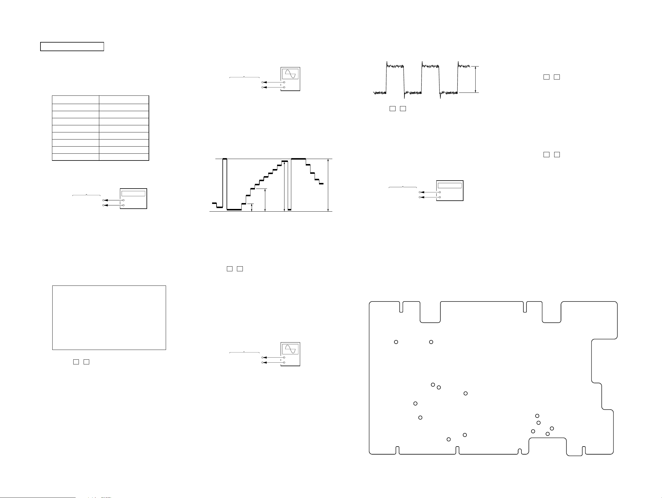
2. CONTRAST ADJUSTMENTS
Setting:
oscilloscop
(DC range)
MONITOR board
TP926
TP912 (GNG)
Procedure:
1. Input 10 steps signal (NTSC, gray scale) from VIDEO 2 input
jack.
2. Connect an oscilloscope to the TP926 and TP912 (GND) on
the MONITOR board.
3. Enter the MONITOR1 mode in the test mode.
4. Confirm that the waveform of oscilloscope is as following
figure.
GND
Specified value:
BPL : 5.00 V ±0.03 V
G1 : 2.13 V ±0.03 V
BRT : 0.68 V ±0.03 V
CNT : 4.83 V ±0.03 V
5. Press the V / v button on the remote commander to select
each item, and adjust the each item values by pressing
the [VOL ---]/[VOL +] button on the remote commander so
that the waveform of the oscilloscope becomes as above
specified values.
6. Repeat about each item until all specified value becomes
specified value.
7. Press the [BACK] button to save the adjusted data.
+
–
CNTG1BRT
BP
4. Confirm that the waveform of oscilloscope is as following
figure.
COM
5. Press the V / v button on the remote commander several
times to select the “COM”.
6. Adjust the “COM” value by pressing the [VOL ---] / [VOL
+] button on the remote commander so that the value of
frequency counter becomes 5.56 V ±0.05 V.
7. Press the [BACK] button to save the COM level on the
waveform adjusted data.
4. SUB CARRIER CONFIRMATION
Setting:
frequency counte
MONITOR board
TP462
TP122 (GND)
Procedure:
1. Input NTSC color bar signal from VIDEO 2 input jack.
2. Connect a frequency counter to the TP462 and TP122 (GND)
on the MONITOR board.
3. Confirm that the value of frequency counter is 3.579545 MHz
±100 Hz.
4. Change the input signal to PAL color bar.
5. Confirm that the value of frequency counter is 4.433619 MHz
±100 Hz.
Connecting Location:
– MONITOR Board (Conductor Side) –
+
–
5. NTSC FLICKER ADJUSTMENT
Procedure:
1. Input color bar signal (NTSC, all white, 40%) from the VIDEO
2 input jack.
2. Enter the MONITOR2 mode in the test mode.
3. Press the V / v button on the remote commander several
times to select the “VDN”.
4. Adjust the “VDN” value by pressing the [VOL ---] / [VOL
+] button on the remote commander so that the flicker
becomes optimally.
5. Press the [BACK] button to save the adjusted data.
6. PAL FLICKER ADJUSTMENT
Procedure:
1. Input color bar signal (P AL, all white, 40%) from the VIDEO
2 input jack.
2. Enter the MONITOR2 mode in the test mode.
3. Press the V / v button on the remote commander several
times to select the “VDP”.
4. Adjust the “VDP” value by pressing the [VOL ---] / [VOL
+] button on the remote commander so that the flicker
becomes optimally.
5. Change the input signal to NTSC color bar.
6. Press the [BACK] button to save the adjusted data.
5. Press the V / v button on the remote commander several
times to select the “VCO”.
6. Adjust the VCO value by pressing the [VOL ---] / [VOL +] button
on the remote commander so that the value of frequency counter
becomes 15.734 kHz ±0.05 kHz.
7. Press the [BACK] button to save the adjusted data.
XTL-W7000
3. V-COM ADJUSTMENT
Setting:
MONITOR board
TP916
TP912 (GNG)
Procedure:
1. Input 10 steps signal (NTSC, gray scale) from VIDEO 2 input
jack.
2. Connect an oscilloscope to the TP916 and TP912 (GND) on
the MONITOR board.
3. Enter the MONITOR1 mode in the test mode.
oscilloscop
(DC range)
+
–
TP204
TP121
TP205TP201
TP203
TP202
TP822
TP462
TP822
TP929
TP926
TP931
TP912
TP916
2323
 Loading...