

Sony XTL-750W, XVM-750WEX Service manual
XTL-750W/XVM-750WEX
SERVICE MANUAL
Monitor : XVM-753W
This set consists of the following units.
•
XTL-750W XVM-750WEX
MONITOR XVM-753W XVM-753W
HIDEAWAY UNIT XT-993V XA-602
REMOTE COMMANDER RM-X86
ANTENNA VCA-114
AEP Model
UK Model
The XTL-750W has a monitor change to the XTL-6100MK2.
The XVM-750WEX has a monitor change to the XVM-61EX.
This service manual only describes the monitor and accessories and packing materials.
Refer to the service manual for XTL-6100MK2 (9-926-587-11) for information on the hideaway unit XT-993V.
Refer to the service manual for XVM-61EX/6100 (9-925-661-11) for information on the hideaway unit XA-602.
SPECIFICATIONS
Monitor (XVM-753W)
System Liquid crystal color display
Display Transparent TN LCD panel
Drive system TFT active matrix system
Picture size 7 in.; 155.52 × 87.75 mm,
178.57 mm
(w × h, diagonally)
Picture segment
336,960 (w 1440 × h 234)
Speaker type 35 × 20 mm dynamic speaker × 2
Power requirements
12 V DC car battery
(negative ground)
Current drain Approx. 1.0 A
Dimensions 215 × 126.5 × 34 mm (w × h × d)
Operating temperature
5˚C ~ +45˚C
Mass Approx. 650 g
Wireless remote (RM-X86: XTL-750W)
Power requirements
AA (R6) battery × 2
Operable range Approx. 3 m
Dimensions 62 × 25 × 115 mm (w × h × d)
Mass Approx. 100 g
(including batteries)
– Continued on next page –
MOBILE COLOR TV
EXTENSION MONITOR SYSTEM
XTL-750W
MICROFILM
XVM-750WEX
1

TV aerial (VCA-114: XTL-750W)
Cord 5 m, 75 ohm
Supplied accessories
Wireless remote RM-X86 (1)
(XTL-750W)
Power input cord (1) (XTL-750W)
Monitor cable (1)
TV aerial VCA-114 (1)
(XTL-750W)
Parts for installation and
connections (1 set) (XTL-750W)
Mounting kit (1 set) (XTL-750W)
Design and specifications are subject to change
without notice.
Notes on Chip Component Replacement
• Never reuse a disconnected chip component.
• Notice that the minus side of a tantalum capacitor may be
damaged by heat.
TABLE OF CONTENTS
1. GENERAL
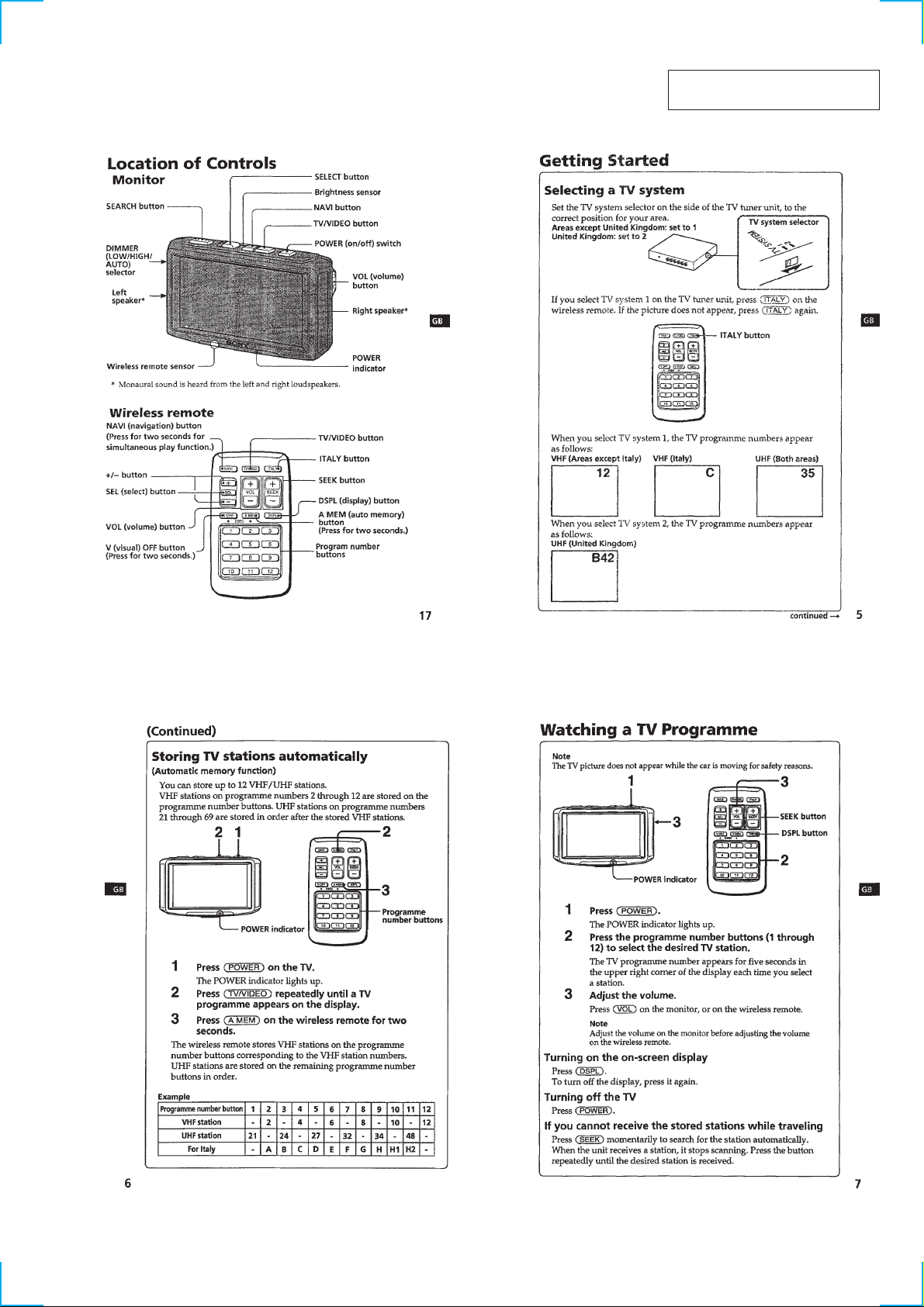
Location of Controls............................................................... 3
Getting Started........................................................................ 3
Watching a TV Programme .................................................... 3
Viewing the Wide Screen ....................................................... 4
Watching a Video.................................................................... 4
Listening to the TV/video Sound
with the Picture Off ................................................................ 4
Adjusting the Picture .............................................................. 5
Adjusting the Screen Brightness ............................................ 5
2. DISASSEMBLY
2-1. Rear Panel Assy ................................................................. 6
2-2. Main Board ........................................................................ 6
3. ELECTRICAL ADJUSTMENTS.................................. 7
4. DIAGRAMS
4-1. Block Diagram –Monitor Section– .................................... 9
4-2. Printed Wiring Boards –Monitor Section–....................... 10
4-3. Schematic Diagram –Monitor Section (1/2)– .................. 12
4-4. Schematic Diagram –Monitor Section (2/2)– .................. 13
5. EXPLODED VIEW
5-1. Monitor Section (XVM-753W) ....................................... 15
6. ELECTRICAL PARTS LIST ................................... 16
2
SECTION 1
GENERAL
This section is extracted from
XTL-750W’s instruction manual.
3

456

g
d
SECTION 2
DISASSEMBLY
Note : Follow the disassembly procedure in the numerical order given.
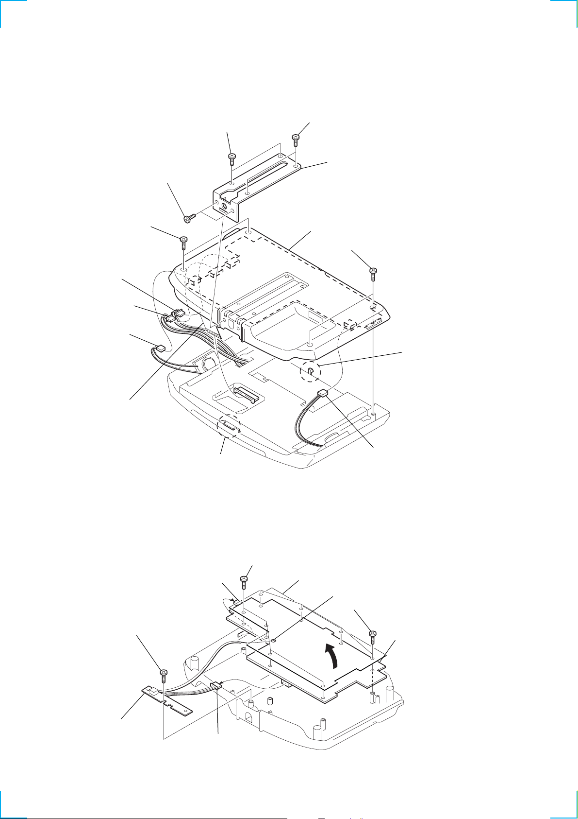
2-1. REAR PANEL ASSY
2
screws (2.6x5)
3
screws (2.6x5)
5
screws (M2x6), tapping
7
CN601
8
CN602
1
screws (2.6x5)
4
stand bracket (W)
qs
rear panel assy
6
screws (M2x6), tappin
2-2. MAIN BOARD
9
CN301
0
connector
claw
5
screws (M2x6), tapping
7
sheetswitch
qa
CN302
3
Unsolder.
6
screws (M2x6), tapping
claw
1
screw (M2x6), tapping
4
MONITOR
SUB board
2
CN101
8
MAIN boar
 Loading...