

Sony XTL-750-W Service manual
XTL-750W
SERVICE MANUAL
Ver 1.1 2001. 03
Tuner unit :
XT-992V (US model)
XT-991V (Hong Kong model)
This set consists of the following units.
•
US model Hong Kong model
MONITOR XVM-752W XVM-751W
TUNER UNIT XT-992V XT-991V
REMOTE COMMANDER RM-X63N RM-X63E
ANTENNA VCA-114 VCA-114
US Model
Hong Kong Model
Monitor :
XVM-752W (US model)
XVM-751W (Hong Kong model)
Monitor (XVM-752W: US, XVM-751W: Hong Kong)
System Liquid crystal color display
Display Transparent TN LCD panel
Drive system TFT active matrix system
Picture size 7 in.; 155.52 × 87.75 mm,
178.57 mm
(w × h, diagonally)
Picture segment
336,960 (w 1440 × h 234)
Speaker type 35 × 20 mm dynamic speaker × 2
Power requirements
12 V DC car battery
(negative ground)
Current drain Approx. 1.0 A
Dimensions 215 × 126.5 × 34 mm (w × h × d)
Operating temperature
5˚C ~ +45˚C
Mass Approx. 650 g
TV tuner unit (XT-992V: US,
XT-991V: Hong Kong)
Tele vision system
Hong Kong:
CCIR I,D,K system
US:
NTSC
Color system Hong Kong:
TV: PAL
Video: PAL, NTSC
US:
TV: NTSC
Video: NTSC
SPECIFICATIONS
Channel converge
VHF:1 CH ~ 12 CH (Hong Kong)
2 CH ~ 13 CH (US)
UHF:14 CH ~ 69 CH (US)
21 CH ~ 69 CH (Hong Kong)
Power requirements
12 V DC car battery
(negative ground)
Current drain Approx. 0.5 A
Output terminals
Video output: RCA pin 1 Vp-p,
75 ohm
Audio output: RCA pin –10 dBs,
10 kohm
Monitor output: Square 16 -pin
(exclusive)
– Continued on next page –
MOBILE COLOR TV
9-925-662-12
2001C0400-1
© 2001. 3
Sony Corporation
Audio Entertainment Group
General Engineering Dept.
– 1 –

Input terminals Video input (2 system): RCA pin 1 Vp-p,
75 ohm
Audio input: RCA pin –10 dBs, 10 kohm
Antenna input: mini plug
Navigation input: Square 16 -pin
(exclusive)
RCA pin:
Video 1 Vp-p, 75 ohm
Audio (monaural)
–10 dBs, 10 kohm
Dimensions 202 × 30 × 140 mm (w × h × d)
Mass Approx. 750 g
Wireless remote (RM-X63N: US,
RM-X63E: Hong Kong)
Power requirements
AA (R6) battery × 2
Operable range Approx. 3 m
Dimensions 62 × 25 × 115 mm (w × h × d)
Mass Approx. 100 g
(including batteries)
TV antenna (VCA-114)
Cord 5 m (196 7/8 in.), 75 ohm
Supplied accessories
Wireless remote RM-X63N (1)
(US model)
Wireless remote RM-X63E (1)
(Hong Kong model)
Power input cord (1)
Monitor cable (1)
TV antenna VCA-114 (1)
Parts for installation and
connections (1 set)
Cleaning cloth (1)
Design and specifications are subject to change
without notice.
Notes on Chip Component Replacement
• Never reuse a disconnected chip component.
• Notice that the minus side of a tantalum capacitor may be
damaged by heat.
TABLE OF CONTENTS
1. GENERAL
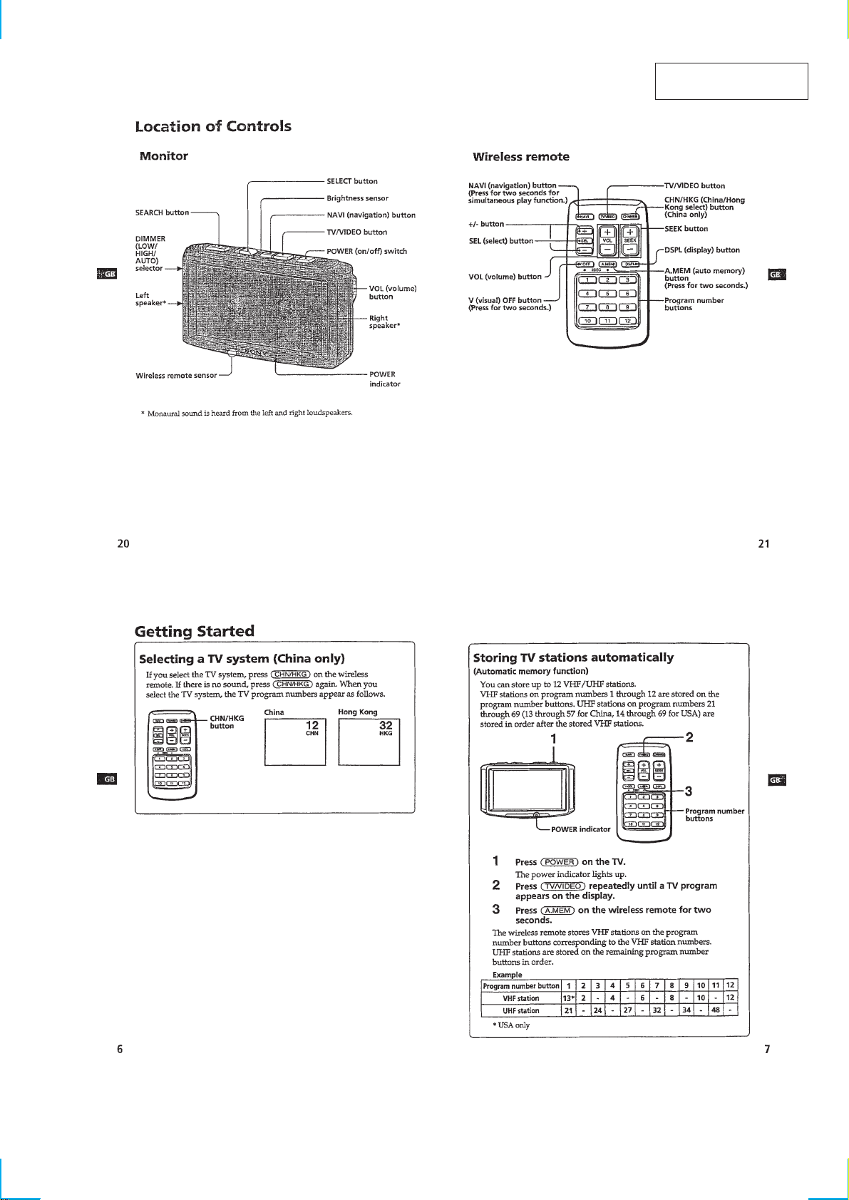
Location of Controls............................................................... 3
Getting Started........................................................................ 3
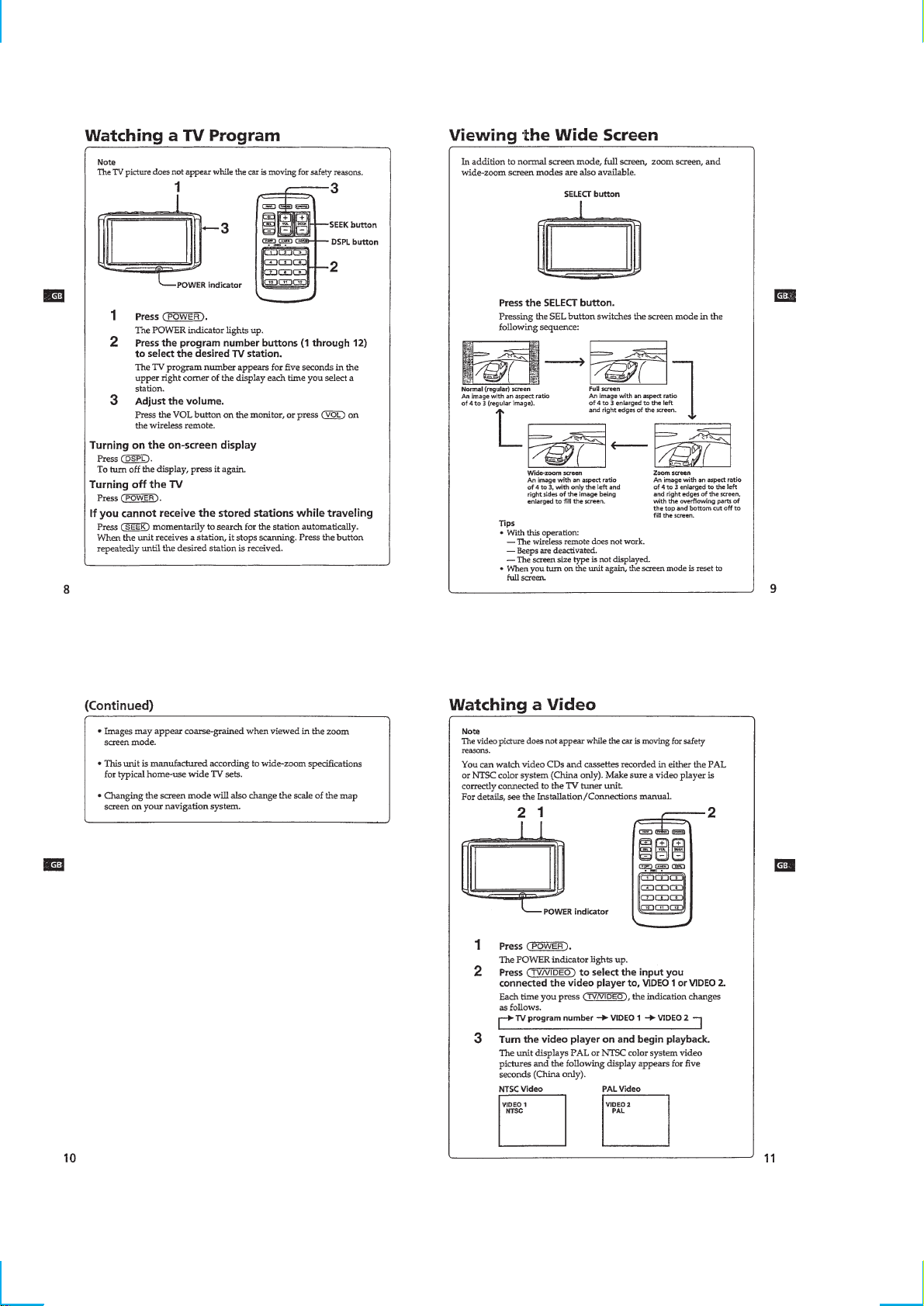
Watching a TV Program ......................................................... 4
Viewing the Wide Screen ....................................................... 4
Watching a V ideo.................................................................... 4
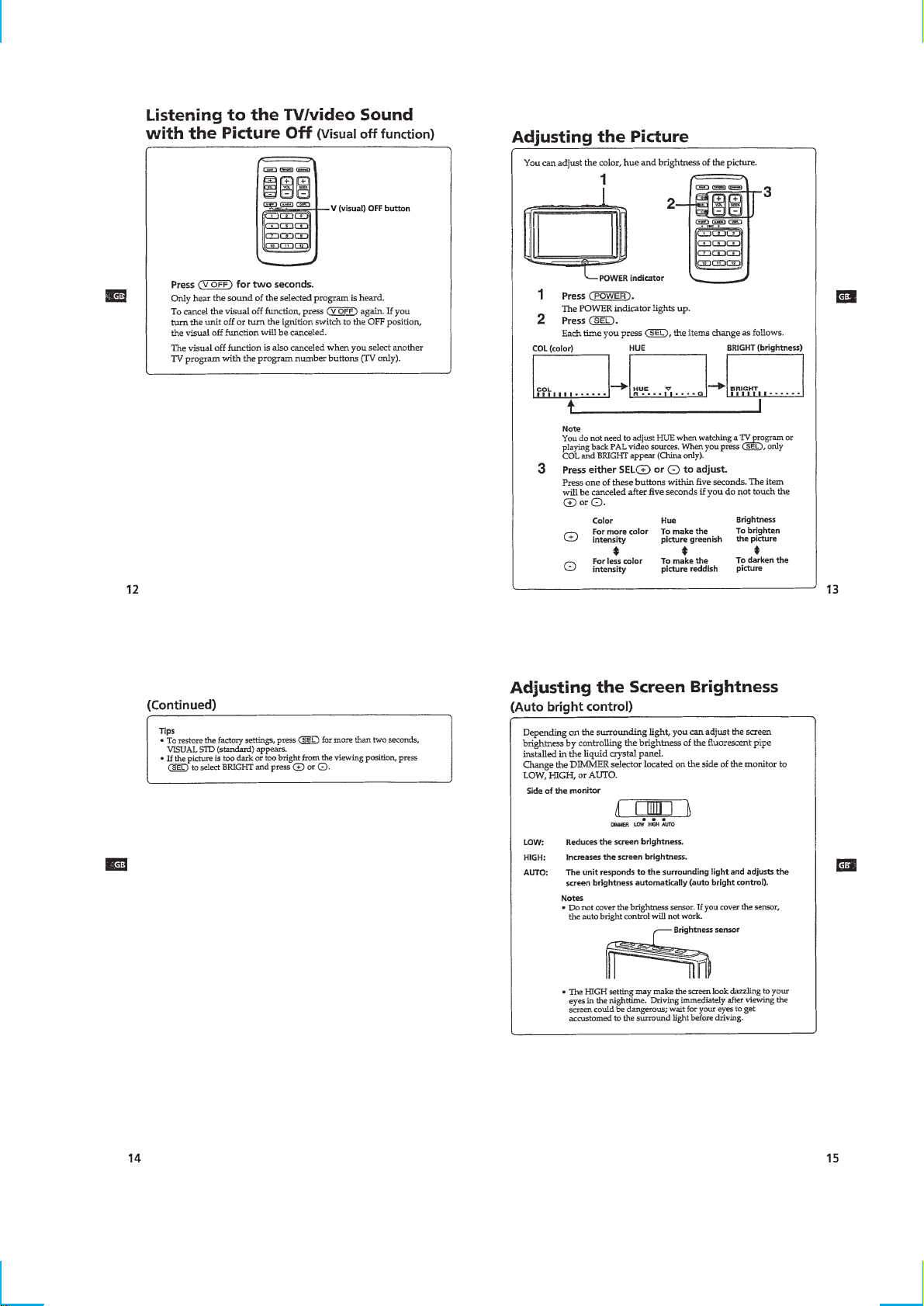
Listening to the TV/video Sound
with the Picture Off ................................................................ 5
Adjusting the Picture .............................................................. 5
Adjusting the Screen Brightness ............................................ 5
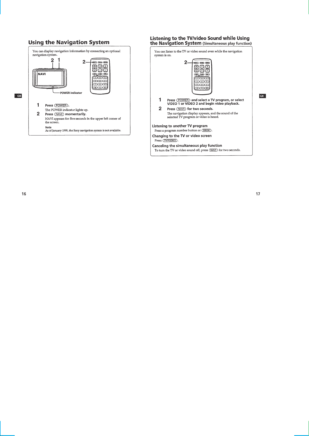
Using the Navigation System ................................................. 6
Listening to the TV/video Sound while Using
the Navigation System............................................................ 6
Connections ............................................................................ 7
2. DISASSEMBLY
2-1. Rear Panel Assy ................................................................. 8
2-2. Main Board ........................................................................ 8
3. ELECTRICAL ADJUSTMENTS
Monitor Section ...................................................................... 9
Tuner Unit Section................................................................ 12
4. DIAGRAMS
4-1. Block Diagram –Monitor Section– .................................. 15
4-2. Block Diagram –Tuner Unit (Video) Section– ................ 17
4-3. Block Diagram –Tuner Unit (Audio) Section–................ 19
4-4. Printed Wiring Boards –Monitor Section–....................... 21
4-5. Schematic Diagram –Monitor Section (1/2)– .................. 25
4-6. Schematic Diagram –Monitor Section (2/2)– .................. 27
4-7. Printed Wiring Board –Tuner Unit (US model)– ............. 29
4-8. Printed Wiring Board
–Tuner Unit (Hong Kong model)– ................................... 33
4-9. Schematic Diagram –Tuner Unit (1/4)–........................... 37
4-10. Schematic Diagram –Tuner Unit (2/4)–........................... 39
4-11. Schematic Diagram –Tuner Unit (3/4)–........................... 41
4-12. Schematic Diagram –Tuner Unit (4/4)–........................... 43
5. EXPLODED VIEWS
5-1. Monitor Section ............................................................... 49
5-2. Tuner Section ................................................................... 50
6. ELECTRICAL PARTS LIST ................................... 51
– 2 –
SECTION 1
GENERAL
This section is extracted
from instruction manual.
– 3 –
– 4 –
– 5 –
– 6 –

– 7 –
SECTION 2
g
d
DISASSEMBLY
Note : Follow the disassembly procedure in the numerical order given.
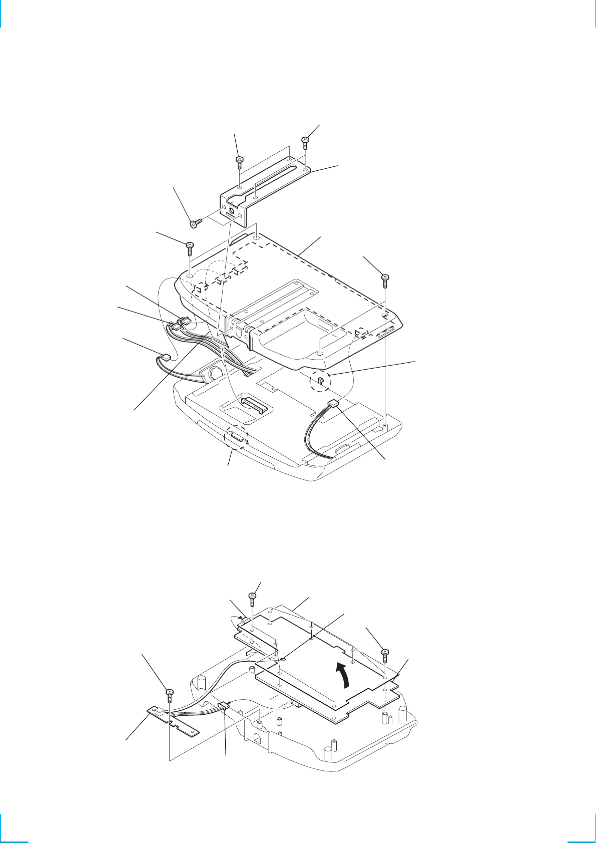
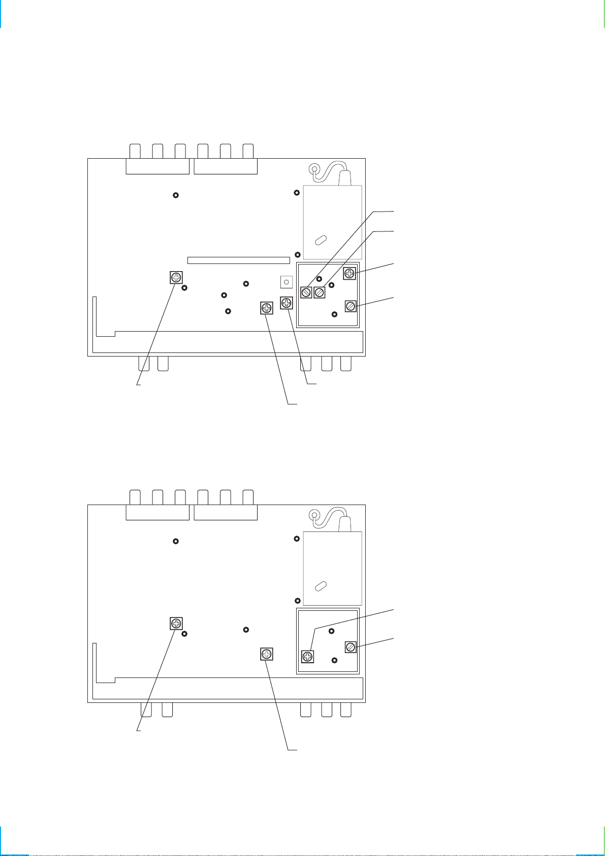
2-1. REAR PANEL ASSY
2
screws (2.6x5)
3
screws (2.6x5)
5
screws (M2x6), tapping
7
CN601
8
CN602
1
screws (2.6x5)
4
stand bracket (W)
!™
rear panel assy
6
screws (M2x6), tappin
2-2. MAIN BOARD
9
CN301
0
connector
claw
5
screws (M2x6), tapping
7
sheetswitch
!¡
CN302
3
Unsolder.
6
screws (M2x6), tapping
claw
1
screw (M2x6), tapping
4
MONITOR
SUB board
2
CN101
– 8 –
8
MAIN boar
W
SECTION 3
ELECTRICAL ADJUSTMENTS
Ver 1.1 2001. 03
MONITOR SECTION
Equipment Used
The measuring equipment below are used for these electrical
adjustments:
• Oscilloscope
• NTSC pattern generator
• Regulated DC power supply
• Digital voltmeter
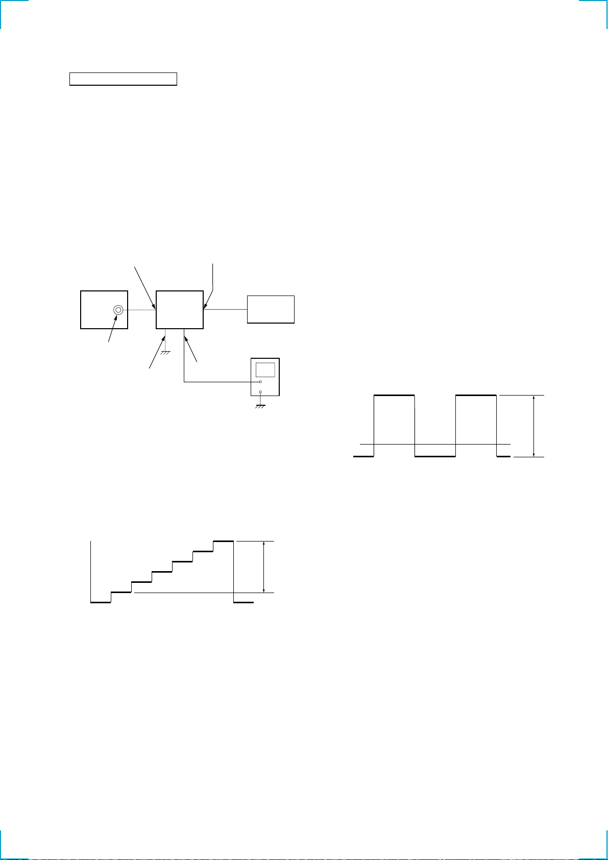
Connection of Equipment
Unless otherwise specified, the measuring equipment should be
connected as shown below:
INPUT (1)
(VIDEO)
NTSC pattern
generator
VIDEO OUT
(75 Ω)
Parking
MONITOR OUT
Tuner unit
XT-991V/992V
ACC cord
Monitor
XVM-751W/752
Regulated DC
power supply
+
–
Inverter Voltage Adjustment
Procedure:
1. Display the gray scale on the monitor screen.
2. Connect a digital voltmeter to TP64 on the MONITOR MAIN
board.
3. Adjust RV601 so that the reading on the digital voltmeter is
7.80 ± 0.05 V.
Adjustment Location: See page 11.
Bright Adjustment
Procedure:
1. Display the gray scale on the monitor screen.
2. Connect a digital voltmeter to TP70 on the MONITOR MAIN
board.
3. Adjust RV201 so that the reading on the digital voltmeter is
2.13 ± 0.02 V.
Adjustment Location: See page 11.
VCOM Adjustment (1)
Procedure:
1. Display the gray scale on the monitor screen.
2. Connect an oscilloscope to TP102 on the MONITOR MAIN
board.
3. Adjust RV210 so that the amplitude of the output waveform is
7.5 ± 0.1 Vp-p.
4. Adjust RV211 so that the lev el A of the output w a vefor m is at
5.5 ± 0.05V DC.
A
Setup for Adjustment
The adjustment signal is a 5-step gray scale signal from a NTSC
pattern generator.
Input the gray scale signal into the tuner unit and connect an oscilloscope to TP14 on the MONITOR MAIN board. Check that the
width between the black and white levels of the gray scale signal is
0.74 Vp-p.
white
0.74Vp-p
black
DC/DC Converter Voltage Adjustment
Procedure:
1. Display the gray scale on the monitor screen.
2. Connect a digital voltmeter to TP57 on the MONITOR MAIN
board.
3. Adjust RV401 so that the reading on the digital voltmeter is
5.35 ± 0.05 V.
Adjustment Location: See page 11.
7.5Vp-p
0V
Adjustment Location: See page 11.
RGB Amplitude Adjustment
Procedure:
1. Display the gray scale on the monitor screen.
2. Connect a digital voltmeter to TP63 on the MONITOR MAIN
board.
3. Adjust RV208 so that the reading on the digital voltmeter is
2.37 ± 0.02 V.
Adjustment Location: See page 11.
γ 2 Adjustment
Procedure:
1. Display the gray scale on the monitor screen.
2. Connect a digital voltmeter to TP67 on the MONITOR MAIN
board.
3. Adjust RV213 so that the reading on the digital voltmeter is
2.19 ± 0.02 V.
Adjustment Location: See page 11.
– 9 –

γ 0 Adjustment
Procedure:
1. Display the gray scale on the monitor screen.
2. Connect an oscilloscope to TP106 on the MONITOR MAIN
board.
3. Adjust RV212 so that the white level of the waveform is at
4.6 ± 0.05V DC.
Adjustment Location: See page 11.
R and B Level Adjustment
Procedure:
1. Display the gray scale on the monitor screen.
2. Connect an oscilloscope to TP107 on the MONITOR MAIN
board.
3. Adjust RV207 so that the white level of the waveform is at
4.6 ± 0.05V DC.
4. Connect an oscilloscope to TP108 on the MONITOR MAIN
board.
5. Adjust RV209 so that the white level of the waveform is at
4.4 ± 0.05V DC.
Adjustment Location: See page 11.
VCOM Adjustment (2)
Procedure:
1. Display the navigation map screen on the monitor screen.
2. Adjust RV211 so as to ensure that the screen has the highest
contrast with no flicker.
Adjustment Location: See page 11.
– 10 –

Adjustment Location:
MONITOR MAIN BOARD
RV211 RV210
RV401
DC/DC
CONVERTER
VOLTAGE
MONITOR MAIN BOARD
VCOM
RV213
RV209 RV207
R AND B LEVEL
(
SIDE B
TP70
)
TP108
γ
2
RV201
BRIGHT
TP106
γ
0
RV212
RV208
AMPLITUDE
TP107
RGB
(
SIDE A
)
RV601
INVERTER
VOLTAGE
TP64
TP67
TP102
TP14
TP63
TP57
– 11 –

TUNER UNIT SECTION
• Use the following equipment for the electrical adjustment.
Equipment
1 Monitor TV (XVM-750W, etc.)
2 Spectrum analyzer
3 TV signal generator
4 Digital voltmeter
5 Oscilloscope
6 Audio analyzer
7 DC power supply
8 Frequency counter
Equipment Connections
Connect the test equipment as shown in the figure below (unless
otherwise instructed) and perform the adjustment.
DC
TV SG
RF out
ANT IN
set
POWER (CN4)
Setup during Adjustment
Use the video signal obtained from the TV signal generator as the
alignment signal, and check that this signal is within video output
signal standards.
power supply
TRAP Adjustment (Hong Kong model)
Procedure:
1. With the Power off, input the output of TG to TP30 (with DC
cut by a capacitor (0.01 µF)).
2. Connect a spectrum analyzer to TP31 (with DC cut by a
capacitor (0.01 µF)).
3. Adjust T1 so that the waveform peak is 39.75 MHz ± 50 Hz.
4. Adjust T2 so that the waveform peak is 30.0 MHz ± 50 Hz.
5. After this adjustment, open TP30 and TP31. (Disconnect the
spectrum analyzer.)
T1= 39.75 MHz
T2= 30.0 MHz
VCO Adjustment
Procedure:
1. No connection to ANT IN. (no signal state)
2. Connect a resistor (10 kΩ) between TP33 and +9 V (TP35).
3. Connect a spectrum analyzer to TP34 (with DC cut by a
capacitor (0.01 µF)).
4. Adjust T3 so that the waveform peak is 38.0 MHz ± 1 kHz
(Hong Kong model) or 45.75 MHz ± 1 kHz (US model).
5. After this adjustment, open TP34. (Disconnect the spectrum
analyzer.)
white (approx. 100%)
0.7 V
0.3 V
red
horizontal sync. signal
Color bar signal from TV signal generator (US model)
white (approx. 100%)
0.7 V
0.3 V
red
horizontal sync. signal
burst signal (flat)
burst signal (flat)
0.3 V
0.3 V
38.0 MHz (Hong Kong model)
45.75 MHz (US model)
AGC Adjustment
Procedure:
1. Set the TV SYSTEM switch to 1.
2. Input a color bar signal of C9ch (192.25 MHz) (Hong Kong
model) or 10ch (193.25 MHz) (US model) and 66 dBµV
(75 Ω OPEN).
3. Connect the digital voltmeter to TP42.
4. Adjust VR1 so that reading on the digital voltmeter is
6.0 ± 0.1 V (Hong Kong model) or 3.0 ± 0.1 V (US model).
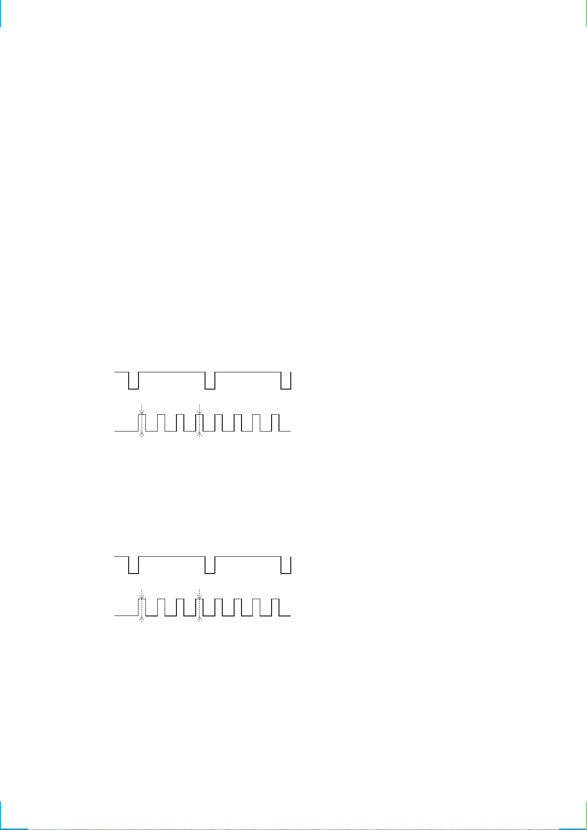
AFT Adjustment
Procedure:
1. Input a color bar signal of C9ch (192.25 MHz) (Hong Kong
model) or 10ch (193.25 MHz) (US model) and 74 dBµV
(75 Ω OPEN).
2. Connect the oscilloscope to TP102.
3. Adjust T3 untill the waveform on the oscilloscope is 2.5 Vp-p.
Color bar signal from TV signal generator (Hong Kong model)
Connection points: See page 14.
Adjustment points: See page 14.
2.5 Vp-p
0 V
Note: Small peaks (dips) coming out from the top of the
waveform are unacceptable.
– 12 –
RGB Decoder FO Adjustment
Procedure:
Hong Kong model:
1. Without INPUT1, INPUT2 inputs (no signal input mode), short
the jumper wire between TP100 and GND.
2. Connect a frequency counter to TP61.
3. Adjust VR6 so that reading on frequency counter is
4.433619 MHz ± 10 Hz.
4. Short the jumper wire between TP106 and GND.
5. Connect a frequency counter to TP61.
6. Confirm that reading on frequency counter is 3.579545 MHz ±
100 Hz.
7. After this adjustment, remove the jumper wires.
US model:
1. Without INPUT1, INPUT2 inputs (no signal input mode), short
the jumper wire between TP100 and GND.
2. Connect a frequency counter to TP61.
3. Adjust VR6 so that reading on frequency counter is
3.579545 MHz ± 100 Hz.
4. After this adjustment, remove the jumper wires.
RGB Decoder Input Level Adjustment
Procedure:
1. Input signal : PAL EBU color bar (INPUT 1 VIDEO)
2. Adjust VR4 so that the white peak 1 (100% white) of
TP111 (B OUT) is at 1.0 Vp-p.
SYNC
124 3
TP111
white blue
DL AMP & DAT Adjustment (Hong Kong model)
Procedure:
1. Adjust DAT so as to minimize the variation between the level
2 and the level 3 of TP111.
2. Adjust VR5 so that the blue level 4 is at 1.0 Vp-p.
3. Set the input to NTSC, and confirm that the blue level 4 is at
1.0 ± 0.1 Vp-p.
SYNC
124 3
TP111
white blue
– 13 –
Connection Points and Adjustment Points:
t
t
– Hong Kong Model –
TP102
TP100
TP106
TP111
TP61
TP42
TP30
TP31
TP34
TP33
T1: TRAP Adjustment
T2: TRAP Adjustment
VR1: AGC Adjustmen
T3: VCO Adjustment
: AFT Adjustment
– US Model –
VR4: RGB Decoder
input Level Adjustment
TP102
TP61
TP100
VR5: DL AMP & DAT Adjustment
VR6: RGB Decoder FO Adjustment
TP42
TP30
TP33
TP34
VR1: AGC Adjustmen
T3: VCO Adjustment
: AFT Adjustment
VR4: RGB Decoder
input Level Adjustment
– 14 –
VR6: RGB Decoder FO Adjustment
SECTION 4
DIAGRAMS
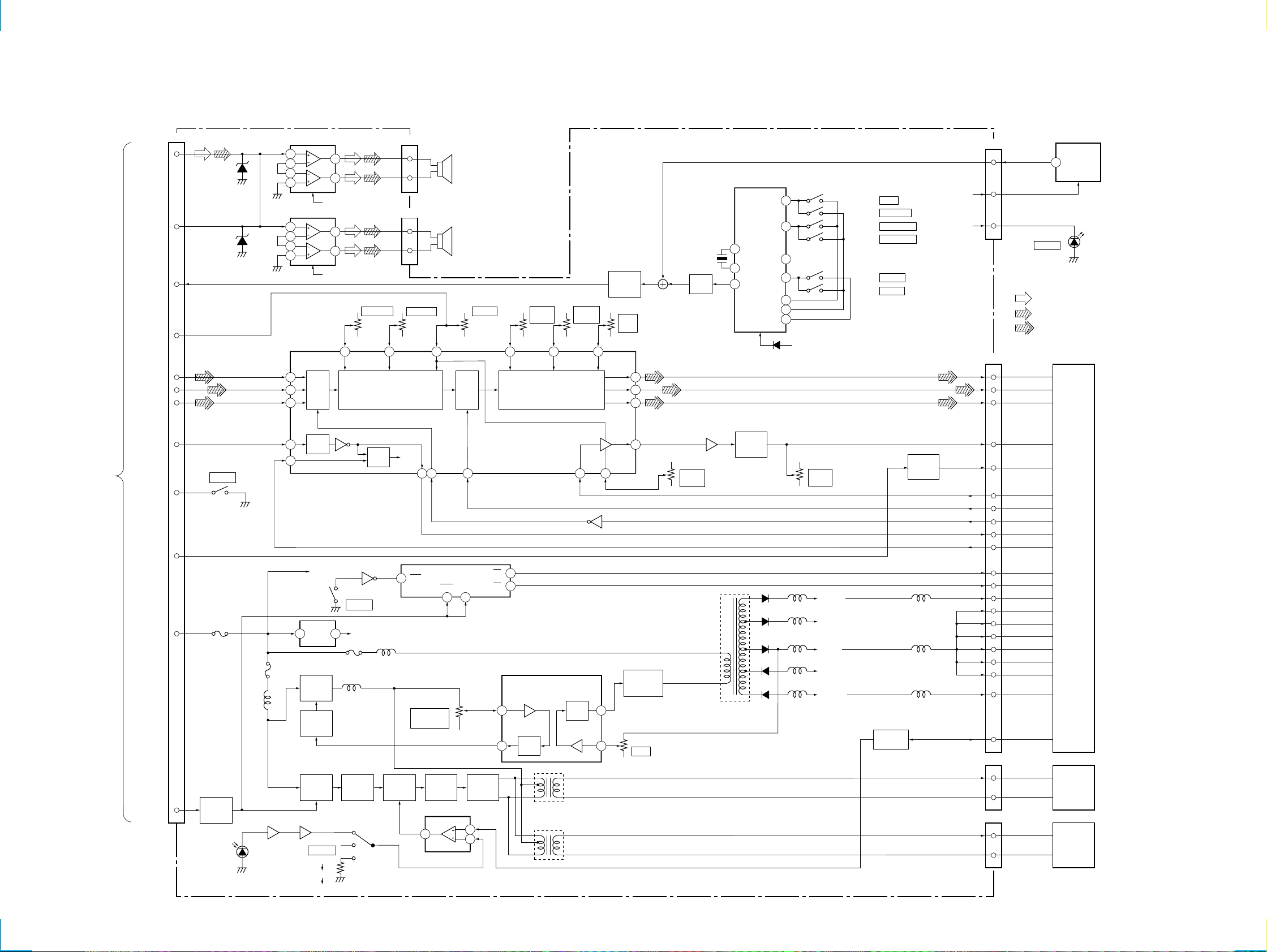
4-1. BLOCK DIAGRAM — MONITOR SECTION —
XTL-750W
TV
TUNER
UNIT
(XT-991V/992V)
AUDIO
(MAIN)
AUDIO
(SUB)
SIRCS
BRIGHT
R IN
G IN
B IN
C. SYNC
POWER SW
WIDE MODE1
(PAL/NTSC)
BL OFF/ON
CN1
3
D301
2
D302
10
5
15
14
13
12
S1
8
16
6
+B
9
04
POWER
F901
BL
CONTROL
Q801, 802
D701
DIMMER
SENSOR
AUDIO POWER AMP IC301
7
8
5
6
AUDIO POWER AMP IC303
7
8
5
6
42
41
40
36
34
F601
L601
DIMMER DISCRIMINATOR IC701
21
B+ (AMP)
B+ (AMP)
INT/
EXT
SW
SYNC
SEP
VIDEO INTERFACE, LED DRIVER
+B
REG
1 2
IC302
B+
SWITCH
Q608
B+
ON/OFF
Q606,607
BL B+
ON/OFF
Q602
57
S701
DIMMER
AUTO
HIGH
LOW
1
3
1
3
26
L602
IC201
Q105
S105
SELECT
B+ (AMP)
REG
Q604
RV213
GAMMA2
GAMMA
BGP
GEN
L505F501
CN302
2
1
CN301
2
1
RV212
GAMMA0
27
AMP
12
BL
DRIVE
Q601
29
BGP
35 39 33 32 37
WIDE MODE SELECT
1CK
RV601
INVERTER
VOLTAGE
SWITCH
Q611
COMPARATOR IC601
7
MAIN/L
SPEAKER
SUB/R
SPEAKER
INV
IC103
1CLR 2CLR
10 13
SP1
SP2
RV201
BRIGHT
INVERTER
Q609, 610
6
5
31
1Q
2Q
3
7
BRIGHT
2
6
DC-DC CONVERTER
ERROR AMP
COMP
RV207
R SUB
IC401
T601
T602
30
AMP
RV209
B SUB
BRIGHT
42
INV IC204
COMP
ERROR AMP
28
10
14
MIX/
BUFFER
Q102, 103
RV208
RGB
AMP
CONVERTER
19
21
24
38
DC-DC
Q502-504
RV401
5V
X101
480kHz
AMP
Q101
V COM AMP
IC203
57
RV210
V COM
AMP
DC-DC
CONVERTER
TRANSFOMER
T501
KEY IN MATRIX
IC102
OSC 2
14
OSC 1
15
13
OUT
V COM
BIAS
Q207-210
D502
D503
D504
D505
D506
S6
S3
S0
S2
K0
K1
K2
D110
CN101
3 SIRCS
5V
11
10
7
9
3
4
5
B+ (5V)
RV211
V COM
DC
L501
B+ (13V)
L502
B+ (7.5V)
L503
B+ (5V)
L504
B- (-5V)
L513
B- (-16V)
S101 NAVI
S102 TV/VIDEO
S103 SEARCH
S104 SEARCH
(+)
S107 VOL
(–)
S108 VOL
BUFFER
Q603, 605
(+)
(–)
PAL/NTSC
CONTROL
B+ (5V)
+B
Q104
L512
L510
L511
2
2
• Signal path
: TV and External Video (AUDIO)
: NAVI (AUDIO)
: VIDEO
CN8
VR
7
VG
8
6
VB
COM
12
NTP
13
FRPT
2
FRPV
5
VCS
24
SYN
3
HSY
1
22
MODW
MODN
23
VGH
4
10
VSH
13
NTP
15
HRV
16
VRV
17
CLKC
21
MODS
VGL
11
PWM
18
CN601
1
HV
GND
2
CN602
HV
1
GND
2
D102
POWER
1
LIQUID
CRYSTAL
DISPLAY
REMOTE
CONTROL
SENSOR
IC101
LCD1
BACK
LIGHT
UNIT1
BACK
LIGHT
UNIT2
– 15 – – 16 –
 Loading...