

Page 1
XR-4200R/4300R/4300RX
SERVICE MANUAL
Photo: XR-4300R
SPECIFICATIONS
Cassette player section
Tape track 4-track 2-channel stereo
Wow and flutter 0.08 % (WRMS)
Frequency response 30 – 18,000 Hz
Signal-to-noise ratio
Cassette type
TYPE II, IV*
TYPE I 58 dB
Tuner section
FM
Tuning range 87.5 – 108.0 MHz
Aerial terminal External aerial connector
Intermediate frequency 10.7 MHz/450kHz
Usable sensitivity 8 dBf
Selectivity 75 dB at 400 kHz
Signal-to-noise ratio 66 dB (stereo),
Harmonic distortion at 1 kHz
Separation 35 dB at 1 kHz
Frequency response 30 – 15,000 Hz
MW/LW
Tuning range MW: 531 – 1,602 kHz
Aerial terminal External aerial connector
Intermediate frequency 10.7 MHz/450 kHz
Sensitivity MW: 30 µV
72 dB (mono)
0.6 % (stereo),
0.3 % (mono)
LW: 153 – 279 kHz
LW: 40 µV
1
61 dB
AEP Model
UK Model
Model Name Using Similar Mechanism XR-C5110R
Tape Transport Mechanism Type MG-25G-136
Power amplifier section
Outputs Speaker outputs
Speaker impedance 4 – 8 ohms
Maximum power output 50 W × 4 (at 4 ohms)
General
Outputs Audio output
Tone controls Bass ±9 dB at 100 Hz
Power requirements 12 V DC car battery
Dimensions Approx. 178 × 50 × 183 mm
Mounting dimensions Approx. 182 × 53 × 162 mm
Mass Approx. 1.2 kg
Supplied accessories Parts for installation and
1
XR-4300RX/4300R only
*
2
XR-4300RX/4300R only
*
Design and specifications are subject to change
without notice.
(sure seal connectors)
Power aerial relay control
lead
Power amplifier control
lead
Telephone ATT control
2
lead*
Treble ±9 dB at 10 kHz
(negative earth)
(w/h/d)
(w/h/d)
connections (1 set)
Front panel case (1)
MICROFILM
FM/MW/LW CASSETTE CAR STEREO
Page 2

TABLE OF CONTENTS
1. GENERAL
Location of controls ........................................................ 3
Resetting the unit ............................................................ 3
Detaching the front panel................................................ 3
Setting the c l o c k .............................................................. 3
Installation....................................................................... 4
Connections ..................................................................... 5
2. DISASSEMBLY ......................................................... 8
3. ASSEMBLY OF MECHANISM DECK........... 10
4. MECHANICAL ADJUSTMENTS ....................... 13
5. ELECTRICAL ADJUSTMENTS......................... 13
6. DIAGRAMS
6-1. Note for Printed Wiring Boards and
Schematic Diagrams ....................................................... 15
6-2. Printed Wiring Board
– MAIN Board (Component Side) – .............................. 16
6-3. Printed Wiring Board
– MAIN Board (Conductor Side) – ................................ 17
6-4. Schematic Diagram – MAIN Board (1/2) – ................... 18
6-5. Schematic Diagram – MAIN Board (2/2) – ................... 19
6-6. Printed Wiring Board – KEY Board –........................... 20
6-7. Schematic Diagram – KEY Board – ............................. 21
6-8. Printed Wiring Board – SUB Board – ........................... 22
6-9. Schematic Diagram – SUB Board – .............................. 22
6-10. IC Pin Function Description ........................................... 26
Flexible Circuit Board Repairing
• Keep the temperature of the soldering iron around 270 ˚C during repairing.
• Do not touch the soldering iron on the same conductor of the
circuit board (within 3 times).
• Be careful not to apply force on the conductor when soldering
or unsoldering.
Notes on chip component replacement
• Never reuse a disconnected chip component.
• Notice that the minus side of a tantalum capacitor may be damaged by heat.
7. EXPLODED VIEWS................................................ 30
8. ELECTRICAL PARTS LIST ............................... 33
2
Page 3
SECTION 1
GENERAL
This section is extracted from
instruction manual.
Location of controls
PTY
S
+
C
DSPL
I
D
-
P
R
S
T
+
-
-
SOURCE
D
I
S
MODE
-
SEEK/AMS
ENTER
–
C
MENU
SOUND
P
R
S
T
OFF
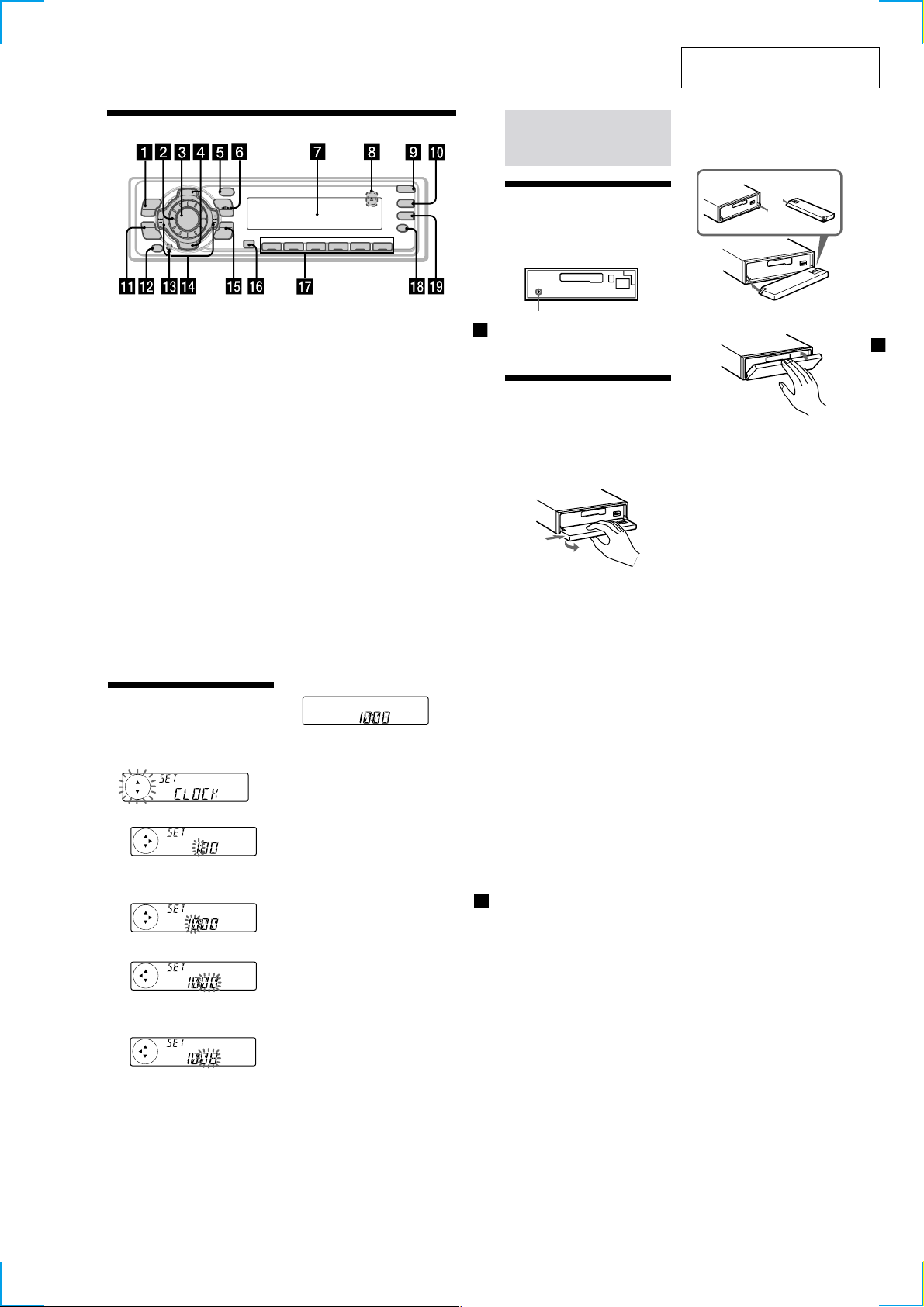
Refer to the pages listed for details.
1 MENU button
9, 11, 12, 13, 15, 17, 19, 22, 24
2 Volume control dial
3 SOURCE (TUNER/TAPE)
button 8, 10, 12, 13, 16, 23
4
PRST +/– (cursor up/down) buttons
8, 9, 11, 12, 13, 15, 17, 18, 19, 22, 24
During radio reception:
Preset stations select 13
5 DSPL/PTY (display mode change/
programme type) button
11, 14, 18, 23, 24
6 MODE button 10, 11, 12, 13, 23
During tape playback:
Playback direction change 10
During radio reception:
BAND select 12
7 Display window
8
Z (eject) button (located on the front side
of the unit behind the front panel)
9 OPEN button 7, 10, 26
q; D-BASS button 23
qa SOUND button 21
qs OFF button*
2
7, 8, 10
REP SHUF
1 2 3 4 56
qd Reset button (located on the front side
of the unit behind the front panel) 7
qf SEEK/AMS –/+ (cursor left/right) buttons
8, 9, 10, 11, 12, 13, 15, 17, 19, 21, 22, 24, 25
Seek 13, 15
Automatic Music Sensor 10, 25
Manual search 13, 25
qg ENTER button
9, 11, 12, 13, 15, 17, 18, 19, 22, 24
qh Receptor for the card remote
commander*
qj Number buttons
During radio reception:
Preset number select 12, 13, 16, 17
During tape playback:
(1) REP 11
qk AF button 15, 17
ql TA button 16, 17
2
10
*
Warning when installing in a car
without ACC (accessory) position on
the ignition key switch
Be sure to press (OFF) on the unit for
two seconds to turn off the clock display
after turning off the engine.
When you press (OFF) only momentarily,
the clock display does not turn off and this
causes battery wear.
3
*
XR-4300RX/4300R only
Attaching the front panel
Place the hole A of the front panel onto the
spindle B on the unit as illustrated, then push
the left side in.
A
B
x
OPEN
D-BASS
TA
AF
Getting Started
Resetting the unit
Before operating the unit for the first time or
after replacing the car battery, you must reset
the unit.
Remove the front panel and press the reset
button with a pointed object, such as a
ballpoint pen.
Reset button
Note
Pressing the reset button will erase the clock
setting and some memorised functions.
Detaching the front panel
You can detach the front panel of this unit to
protect the unit from being stolen.
1
3
Press (OFF).
2
Press (OPEN), then slide the front panel
to the right side, and pull out from the
left side.
1
2
Notes
• Be sure not to drop the panel when detaching it
from the unit.
• If you detach the panel while the unit is still
turned on, the power will turn off automatically
to prevent the speakers from being damaged.
• When you carry the front panel with you, use the
supplied front panel case.
Notes
• Be careful not to attach the front panel upside
down.
• Do not press the front panel too hard against the
unit when attaching it.
• Do not press too hard or put excessive pressure
on the display window of the front panel.
• Do not expose the front panel to direct sunlight
or heat sources such as hot air ducts, and do not
leave it in a humid place. Never leave it on the
dashboard of a car parked in direct sunlight or
where there may be a considerable rise in
temperature.
Caution alarm
If you turn the car ignition off without
removing the front panel, the caution alarm
will beep for a few seconds.
If you connect an optional power amplifier and
do not use the built-in amplifier, the beep
sound will be deactivated.
Setting the cloc k
The clock uses a 24-hour digital indication.
Example: To set the clock to 10:08
1 Press (MENU), then press either side of
(PRST/DISC) or (PRST) repeatedly until
“CLOCK” appears.
1 Press (ENTER).
The hour indication flashes.
2 Press either side of (PRST/DISC) or
(PRST) to set the hour.
3 Press (+) side of (SEEK/AMS).
The minute indication flashes.
4 Press either side of (PRST/DISC) or
(PRST)
to set the minute.
2 Press (ENTER).
The clock starts.
After the clock setting is complete, the
display returns to normal playback mode.
Tips
• You can use the convenient CT function to set
the clock automatically (page 19).
• When the D.INFO mode is set to ON, the time is
always displayed (page 22).
5
7
9
3
Page 4
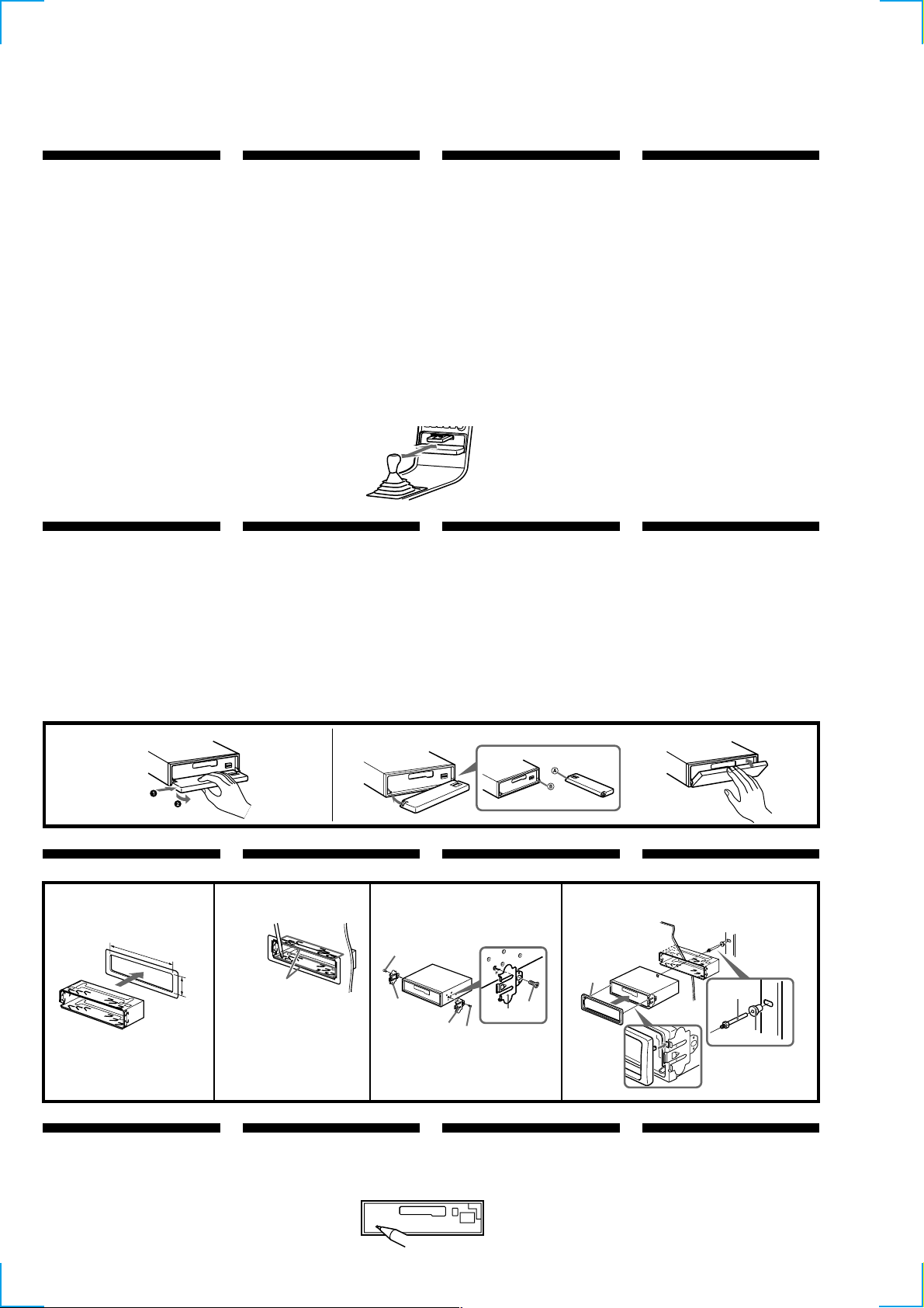
Installation
Instalación
Montering
Instalação
Precautions
•If you mount other Sony equipment with this
unit, it is better to mount this unit in the lower
position.
•There must be a distance of at least 15 cm
between the cassettes slot of the unit and shift
lever to insert cassette easily. Choose the
installation location carefully so the unit does
not interfere with gear shifting and other driving
operations.
•Choose the installation location carefully so that
the unit will not interfere with normal driving
operations.
•Avoid installing the unit in areas subject to dust,
dirt, excessive vibration, or high temperatures,
such as in direct sunlight or near heater ducts.
•Use only the supplied mounting hardware for a
safe and secure installation.
Mounting angle adjustment
Adjust the mounting angle to less than 20°.
How to detach and attach the
front panel
Before installing the unit, detach the front
panel.
A To detach
Before detaching the front panel, be sure to press
(OFF). Press (OPEN), then slide the front panel to
the right side, and pull out the left side.
BTo attach
Place the hole A in the front panel onto the
spindle B on the unit as illustrated, then push the
left side in.
Precauciones
•Si monta otro equipo Sony con esta unidad, es
preferible montar esta unidad en la posición más
baja.
•Para que sea posible insertar la cinta con
facilidad, debe haber una distancia de al menos
15 cm entre la ranura de inserción de cintas de la
unidad y la palanca de cambios.
Instale la unidad en un lugar que no entorpezca
las operaciones de cambio de marchas o de
conducción en general.
•Elija cuidadosamente el lugar de montaje de
forma que la unidad no interfiera las funciones
normales de conducción.
•Evite instalar la unidad donde pueda quedar
sometida a altas temperaturas, como a la luz
solar directa o al aire de calefacción, o a polvo,
suciedad, o vibraciones excesivas.
•Para realizar una instalación segura y firme,
utilice solamente la ferretería de montaje
suministrada.
Ajuste del ángulo de montaje
Ajuste el ángulo de montaje a menos de 20°.
15
cm
Forma de extraer e instalar el
panel frontal
Antes de instalar la unidad, extraiga el panel
frontal.
A Para extraerlo
Antes de extraer el panel frontal, ceriórese de
pulsar (OFF). Después pulse (OPEN) a fin de
abrirlo, después deslícelo hacia la derecha, y por
último tire de su parte izquierda.
B Para instalarlo
Coloque el orificio A del panel frontal en el eje B
de la unidad, como se muestra en la ilustración, y
después presione la parte izquierda.
Säkerhetsföreskrifter
•Om du monterar annan Sony-utrustning till
denna enhet är det bäst att montera denna enhet
i det undre läget.
•För att du ska kunna sätta i och ta ut bandet
måste avståndet vara minst 15 cm mellan
kassettfacket på enheten och växelspaken. När
du installerar enheten väljer du en plats så att
enheten inte är i vägen när du kör.
•Var noga när du väljer var i bilen du monterar
bilstereon, så att den inte sitter i vägen när du
kör.
•Montera inte bilstereon där den utsätts för
värme,
t ex solsken eller varmluft, eller där den utsätts
för damm, smuts och/eller vibrationer.
•Använd endast de medföljande
monteringstillbehören för att vara säker på att
bilstereon monteras på ett säkert och korrekt
sätt.
Tillåten monteringsvinkel
Monteringsvinkeln får inte vara större än 20
grader.
Ta loss/fästa frontpanelen
Ta loss frontpanelen innan du monterar
bilstereon.
A Ta loss frontpanelen
Var noga med att trycka på (OFF) innan
frontpanelen tas loss. Tryck därefter på (OPEN)
för att öppna frontpanelen. Skjut frontpanelen åt
höger och dra dess vänstra del utåt för att ta loss
frontpanelen.
B Fästa frontpanelen
Placera frontpanelen så att hålet A på
frontpanelen träs över axeln B på bilstereon
enligt illustrationen. Tryck därefter frontpanelens
vänstra del inåt.
Precauções
•É preferível montar este aparelho na posição
mais baixa, se quiser montar simultaneamente
outros equipamentos da Sony.
•Para colocar com facilidade a cassete, deve haver
uma distância de pelo menos 15 cm entre a
ranhura de introduçäo da cassete e a alavanca
das mudanças.
Escolha o local de instalaçäo de forma a que o
aparelho näo interfira com as mudanças de
velocidade ou com as outras manobras de
conduçäo.
•Escolha com cuidado um local apropriado para
a montagem do aparelho, para que este não
interfira com as manobras necessárias à
condução do veículo.
•Evite instalar o aparelho onde possa estar sujeito
a altas temperaturas, como em locais expostos
directamente à luz do sol, ao ar quente dos
aquecimentos, ou sujeitos a pó, sujidade ou
vibração excessiva.
•Para efectuar uma instalação segura utilize
unicamente o hardware de montagem fornecido.
Ajuste do ângulo de montagem
Ajuste o ângulo de montagem a menos de 20°.
Para retirar e colocar o painel
frontal
Retire o painel frontal antes de iniciar a
instalação do aparelho.
A Para retirar
Antes de retirar o painel frontal, tem de carregar
primeiro em (OFF). A seguir, carregue em
(OPEN) para soltar o painel frontal e empurre-o
para a direita. Depois puxe o lado esquerdo do
painel para fora.
B Para colocar
Coloque o orificio A do painel frontal no eixo B
do aparelho tal como ilustrado, e depois carregue
no lado esquerdo para dentro.
A
Installation in the dashboard
1
182 m
m
53 m
m
1
Reset button
When the installation and connections are
complete, be sure to press the reset button with a
ballpoint pen, etc.
B
Instalación en el salpicadero Montera på instrumentbrädan
2
Bend these claws outward
for a tight fit, if necessary.
Si es necesario, doble estas
uñas hacia fuera para que
encaje firmemente.
För att få en tät passning
böj dessa flikar vid behov.
Se necessário, dobre as
unhas para prender melhor.
Botón de restauración
Cuando finalice la instalación y las conexiones,
cerciórese de pulsar el botón de restauración con
un bolígrafo, etc.
3
5
6
6
5
5
6
Nollställningsknappen
Kom ihåg att använda en penna eller något annat
spetsigt föremål för att trycka på
nollställningsknappen när anslutningen och
monteringen är klar.
4
Dashboard
Salpicadero
Instrumentbräda
Tablier
4
c
Instalação no tablier
Fire wall
Panel cortafuegos
Brandsäker
mellanvägg
1
Botão de reinicialização
Quando terminar a instalação e as ligações, não se
esqueça de carregar no botão de reinicialização
com a ponta de uma caneta, esferográfica, etc.
Painel corta-fogo
2
3
4
Page 5

Connections
Conexiones
Anslutning
Ligações
Cautions
•This unit is designed for negative earth 12 V DC
operation only.
•Be careful not to pinch any wires between a
screw and the body of the car or this unit or
between any moving parts such as the seat
railing, etc.
•Connect the power connecting cord 8 to the
unit and speakers before connecting it to the
auxiliary power connector.
•Run all earth wires to a common earth point.
•Connect the yellow cord to a free car circuit
rated higher than the unit’s fuse rating. If you
connect this unit in combination with other
stereo components, the car circuit they are
connected to must be rated higher than the sum
of the individual components’ fuse rating. If
there are no car circuits rated as high as the
unit’s fuse rating, connect the unit directly to the
battery. If no car circuits are available for
connecting this unit, connect the unit to a car
circuit rated higher than the unit’s fuse rating in
such a way that if the unit blows its fuse, no
other circuits will be cut off.
Warning when installing in a car
without ACC (accessory) position
on the ignition key switch
Be sure to press (OFF) on the unit for two
seconds to turn off the clock display after
turned off the engine.
When you press (OFF) momentarily, the clock
display does not turn off and this causes battery
wear.
Precauciones
•Esta unidad ha sido diseñada para alimentarse
con 12 V CC, negativo a masa, solamente.
•Tenga cuidado de no atrapar ningún cable entre
algún tornillo y la carrocería del automóvil o
esta unidad o entre las partes móviles, como por
ejemplo los raíles del asiento, etc.
•Conecte el cable de conexión de alimentación 8
a la unidad y los altavoces antes de conectarlo al
conector de alimentación auxiliar.
•Conecte todos los conductores de puesta a
masa a un punto com ún.
•Conecte el cable amarillo a un circuito libre del
automóvil de potencia nominal superior a la del
fusible de la unidad. Si conecta esta unidad en
combinación con otros componentes estéreo, la
potencia nominal del circuito del automóvil a los
que dichos componentes estén conectados debe
ser superior a la suma de la potencia nominal
del fusible de los componentes. Si no existen
circuitos de automóvil de potencia nominal tan
alta como la del fusible de la unidad, conecte
ésta directamente a la batería. Si no hay circuitos
de automóvil disponibles para conectar esta
unidad, conecte la misma a un circuito de
automóvil de potencia nominal superior a la del
fusible de la unidad de forma que no se
desactiven otros circuitos si el fusible de dicha
unidad se funde.
Advertencia sobre la instalación
en un autom óvil que no
disponga de posición A CC
(accesorios) en el interruptor de
la llave de encendido
Asegúrese de pulsar (OFF) en la unidad
durante dos segundos para desactivar la
indicación del reloj una vez apagado el motor.
Si pulsa (OFF) momentáneamente, la indicación
del reloj no se desactivará y esto causará el
desgaste de la batería.
Säkerhetsföreskrifter
•Denna bilstereo är endast avsedd för anslutning
till ett negativt jordat, 12 V bilbatteri.
•Var noga med att inga kablar kläms mellan
någon skruv eller att de blir klämda mellan
rörliga delar som t.ex. bilsätet.
•Anslut strömkabeln 8 till enheten och
högtalarna innan du ansluter den till den yttre
strömanslutningen.
•Dra samtliga jordledningar till en och samma
jordningspunkt.
•Anslut den gula kabeln till en ledig bilkrets med
ett högre amperetal än enhetens. Om du kopplar
både denna enhet och andra stereokomponenter
till en och samma bilkrets, måste den bilkrets de
kopplas till ha en högre ampere än summan av
de enskilda delarnas amperestyrka. Om det inte
finns några bilkretsar med en så hög
amperestyrka som enhetens ska du ansluta
enheten direkt till batteriet. Om inga bilkretsar
finns för anslutning till enheten ska du ansluta
enheten till en bilkrets med ett högre amperetal
än enhetens säkring, så att det är denna som går
i stället för bilens.
Var försiktig när du gör
installationen i en bil där
tändningsl
åset saknar
tillbehörsläge (ACC)
Glöm inte att trycka på (OFF) på enheten
under två sekunder för att stänga av klockans
teckenfönster efter det att du har stängt av
motorn.
Om du bara trycker på (OFF) ett kort ögonblick
slocknar inte klockans teckenfönster vilket kan
leda till att batteriet laddas ur.
Cuidado
•Este aparelho foi concebido para funcionar
somente com corrente contínua de 12 V com
negativo à massa.
•Tenha cuidado para que os fios não fiquem
entalados entre os parafusos e a carroçaria do
automóvel ou a caixa do aparelho nem entre as
peças móveis, por exemplo, as calhas dos
bancos, etc.
•Ligue o cabo de alimentação de corrente 8 ao
aparelho e aos alifalantes antes de o ligar ao
conector de corrente auxiliar.
•Ligue todos os cabos de massa num ponto de
massa comum.
•Ligue o cabo amarelo a um circuito eléctrico
livre do automóvel, cuja potência nominal seja
superior à dos fusíveis do aparelho. Se ligar este
aparelho em série com outros componentes
estéreo, a potência nominal do circuito eléctrico
do automóvel onde os ligar tem de ser superior
à soma da potência nominal dos fusíveis de
todos os componentes individuais. Se não
houver nenhum circuito eléctrico do automóvel
com uma potência nominal tão elevada como a
dos fusíveis do aparelho, ligue-o directamente à
bateria. Se não estiver disponível nenhum
circuito eléctrico do automóvel para ligação
deste aparelho, ligue-o a um circuito eléctrico do
automóvel com uma potência nominal superior
à dos fusíveis do aparelho, de tal modo que, se o
aparelho rebentar os fusíveis respectivos,
nenhum outro circuito seja cortado.
Aviso sobre a instalação num
automóvel sem posição ACC
(acessórios) na chave de ignição
Verifique se carregou em (OFF) no aparelho
durante dois segundos para desactivar o visor
do relógio depois de ter desligado o motor.
Se carregar ligeiramente em (OFF), não desactiva
o visor do relógio o que provoca o desgaste da
bateria.
Notes of connection example
Notes on the control leads
• The power aerial control lead (blue) supplies +12 V
DC when you turn on the tuner or when you
activate the ATA (Automatic Tuner Activation), AF
(Alternative Frequency) or the TA (Traffic
Announcement) function.
• A power aerial without a relay box cannot be used
with this unit.
• When your car has a built-in FM/MW/LW aerial in
the rear/side glass, it is necessary to connect the
power aerial control lead (blue) or the accessory
power input lead (red) to the power terminal of the
existing aerial booster. For details, consult your
dealer.
Warning
If you have a power aerial without a relay box,
connecting this unit with the supplied power
connecting cord 8 may damage the aerial.
Memory hold connection
When the yellow power input lead is connected,
power will always be supplied to the memory circuit
even when the ignition switch is turned off.
Notes on speaker connection
• Before connecting the speakers, turn the unit off.
• Use speakers with an impedance of 4 to 8 ohms, and
with adequate power handling capacities.
Otherwise, the speakers may be damaged.
• Do not connect the terminals of the speaker system
to the car chassis, and do not connect the terminals
of the right speaker with those of the left speaker.
• Do not attempt to connect the speakers in parallel.
• Do not connect any active speakers (with built-in
amplifiers) to the speaker terminals of the unit.
Doing so may damage the active speakers. Be sure
to connect passive speakers to these terminals.
Notas de ejemplo de conexiones
Notas sobre cables de control
• El cable de control (azul) de la antena motorizada
suministra + 12 V CC al activar el sintonizador o la
funci ón ATA (activaci ón autom ática del
sintonizador), AF (frecuencias alternativas) o TA
(anuncios de tráfico).
• Con esta unidad no podr á utilizarse una antena
motorizada sin caja de relés.
• Si el autom óvil dispone de antena de FM/MW/LW
incorporada en el cristal trasero/lateral, será
necesario conectar el cable de control de antena
motorizada (azul) o el cable de entrada de
alimentaci ón accesoria (rojo) al ter minal de potencia
del amplificador de antena existente. Para más
informaci ón, consulte con el proveedor.
Advertencia
Si dispone de una antena motorizada sin dispositivo
de relé, la conexión de esta unidad con el cable de
conexión de alimentaci ón 8 suministrado puede
dañar la antena.
Conexión para protección de la memoria
Si conecta el cable de entrada de alimentaci ón
amarillo, el circuito de la memoria recibir á siempre
alimentaci ón, incluso aunque ponga la llave de
encendido en la posición de apagado.
Notas sobre la conexión de los altavoces
• Antes de conectar los altavoces, desconecte la
alimentaci ón de la unidad.
• Utilice altavoces con una impedancia de 4 a
8 ohmios, y con la potencia máxima admisible
adecuada, ya que de lo contrario podr ía dañarlos.
• No conecte los terminales del sistema de altavoces al
chasis del autom óvil, ni los del altavoz izquierdo a
los del derecho.
• No intente conectar los altavoces en paralelo.
• No conecte altavoces activos (con amplificadores
incorporados) a los terminales de altavoces de la
unidad. Si lo hiciese, podr ía dañar tales altavoces.
Por lo tanto, cerciórese de conectar altavoces pasivos
a estos terminales.
Att observera angående
anslutningsexemplen
Att observera angående de olika styrkablarna
• Motorantennens styrkabel (bl å) leder + 12 volts
likstr öm när kanalv äljaren slås på eller när
radiomottagningsautomatik ATA, mottagning av
alternativa frekvenser AF eller mottagning av
trafikmeddelanden TA aktiverats.
• En motorantenn utan styrrel ädosa kan inte anslutas
till denna bilstereo.
• Om bilen har en FM/MW/LW-antenn som är inbyggd
i sido- eller bakrutan, måste du ansluta
motorantennens styrkabel (bl å) eller
tilbeh örsströmkabeln (röd) till strömterminalen på
antennf örstärkaren. Din återf örsäljare kan ge dig
mer information.
Varning
Om du har en motorantenn utan rel ädosa kan
antennen skadas om du ansluter enheten med den
medf öljande str ömkabeln 8.
Anslutning för minnesstöd
När du anslutit den gula, ingående str ömkabeln
försörjs minneskretsen med ström hela tiden, även när
tändl åset slås ifrån.
Att observera angående högtalarnas anslutning
• Slå av bilstereon innan du ansluter högtalarna.
• Anslut endast högtalare, vars impedans varierar från
4 till 8 ohm och som har tillr äcklig
effekthanteringskapacitet för att skydda högtalarna
mot skador.
• Anslut inte något av högtalaruttagen till bilens
chassi. Anslut inte heller uttagen på höger högtalare
till uttagen p å vänster högtalare.
• Anslut inte högtalarna parallellt.
• Anslut inte aktiva högtalare (med inbyggda slutsteg)
till bilstereons högtalaruttag, eftersom de kan skada
de aktiva h ögtalarna. Var noga med att bara ansluta
passiva högtalare till dessa uttag.
Notas sobre o exemplo de
ligação
Notas sobre os fios de controlo
• O fio de controlo da antena eléctrica (azul) fornece
+12 V CC quando ligar o sintonizador ou quando
activar as fun ções ATA (Activa ção autom ática do
sintonizador), AF (frequ ência alternativa) ou TA
(Informa ções de trânsito).
• Não pode utilizar uma antena eléctrica sem caixa de
relé com este aparelho.
• Se o seu autom óvel tiver uma antena de FM/MW/LW
montada no vidro traseiro/lateral, tem de ligar o fio
de controlo da antena eléctrica (azul) ou o fio de
entrada de alimenta ção para os acessórios
(vermelho) ao terminal de alimenta ção do
intensificador do sinal da antena existente.
Advertência
Se a antena eléctrica n ão tiver uma caixa de relé, o
facto de ligar este aparelho com o cabo de
alimenta ção 8 fornecido, pode provocar danos na
antena.
Ligação para alimentação contínua da memória
Quando o fio amarelo de entrada de alimenta ção for
ligado, os circuitos de mem ória ficarão com
alimenta ção continua, mesmo se a chave de igni ção
estiver desligada.
Notas sobre a ligação dos altifalantes
• Antes de ligar os altifalantes, desligue o aparelho.
• Utilize altifalantes com imped ância de 4 a 8 ohm, e
com capacidade admissível de pot ência adequada.
Caso contrário, os altifalantes poder ão sofrer
avarias.
• Não ligue os terminais do sistema de altifalantes ao
chassis do autom óvel, e não ligue os terminais do
altifalante direito aos terminais do altifalante
esquerdo.
• Não tente ligar os altifalantes em paralelo.
• Não ligue nenhum sistema de altifalantes activos
(com amplificadores incorporados) aos terminais dos
altifalantes do aparelho. Caso o fa ça, poderá avariar
o sistema de altifalantes activos. Portanto, n ão se
esqueça de ligar altifalantes passivos a estes
terminais.
5
Page 6
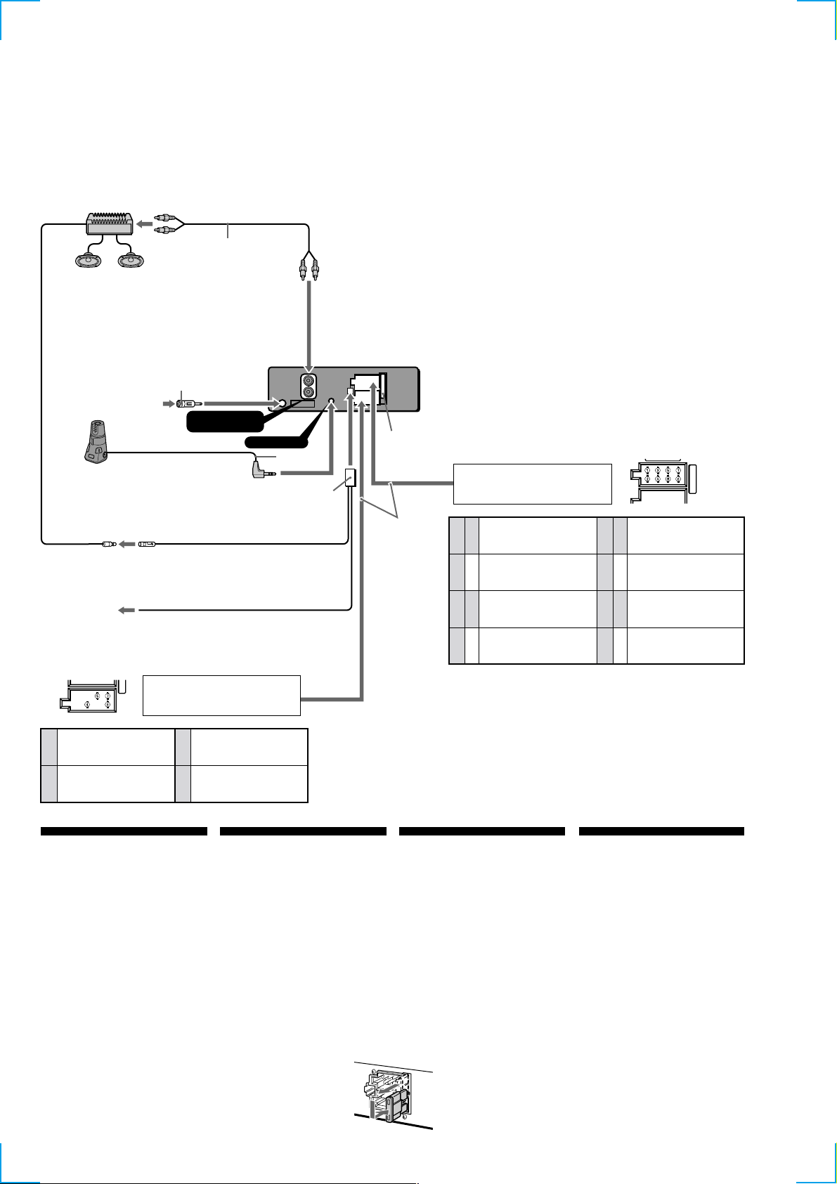
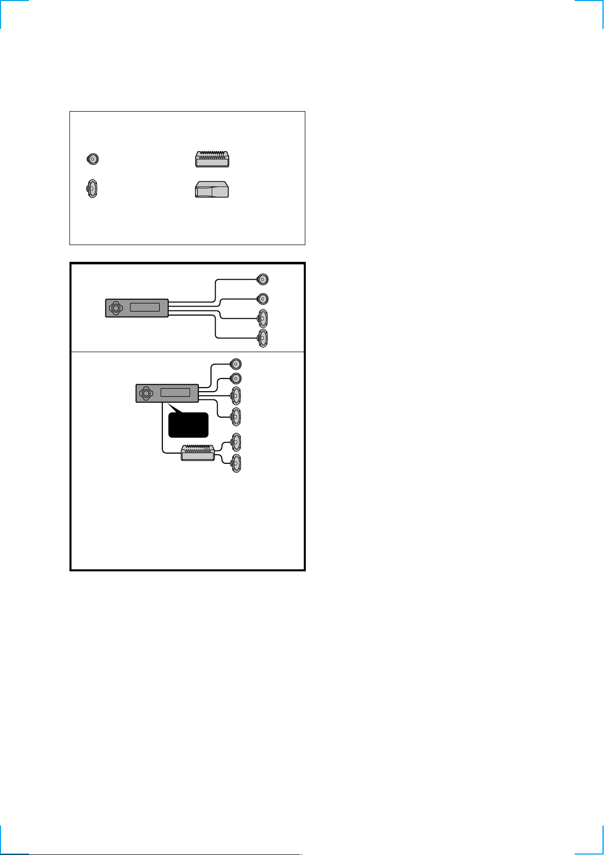
Connection example
Ejemplo de conexiones
Anslutningarna enligt exemplet
Exemplo de ligações
RCA pin cord (not supplied)
Cable con clavijas RCA (no suministrado)
Kabel med RCA-kontakter (medföljer inte)
Cabo de terminais RCA (não fornecido)
1
*
Note for the aerial connecting
If your car aerial is an ISO
(International Organization for
Standardization) type, use the
supplied adapter 7 to connect it.
First connect the car aerial to the
supplied adapter, then connect it to
the aerial jack of the master unit.
2
*
Insert with the cord upwards.
1
*
Nota sobre la conexión de la antena
Si la antena del autom óvil es del
tipo ISO (International Organization
for Standardization), emplee el
adaptador suministrado 7 para
conectarla.
En primer lugar, conecte la antena
del autom óvil al adaptador
suministrado y, a continuaci ón, a la
toma de antena de la unidad
principal.
2
*
Insertar con el cable hacia arriba.
1
*
Angående antennanslutning
Om bilantennen är av ISO-typ
(International Organization for
Standardization), använder du
medf öljande adapter 7 för att
ansluta den.
Anslut först bilantennen till
medf öljande adapter och därefter
till antennuttaget på
huvudenheten.
2
*
Sätt in med kabeln vänd upp åt.
1
*
Nota referente à ligação da antena
Se a antena do autom óvel for uma
antena de tipo ISO (International
Organization for Standardization),
utilize o adaptador fornecido 7
para fazer a ligação respectiva.
Ligue primeiro a antena do
autom óvel ao adaptador fornecido
e depois à tomada de antena do
sistema principal.
2
*
Inserir com o fio virado para cima.
from car aerial
de la antena del automóvil
från bilantenn
da antena do automóvel
to the interface cable of
a car telephone
al cable de interfaz de
un teléfono para
automóvil
till mobiltelefonens
gränssnittskabel
Ao cabo de interface de
um telefone para
automóvel
continuous power supply
suministro de alimentación continua
4
kontinuerlig strömförsörjning
alimentação de corrente contínua
power aerial control
control de antena motorizada
5
motorantenn
antena eléctrica
1
*
1
*
Rotary commander RM-X4S (not supplied)
Mando rotativo RM-X4S (no suministrado)
Vridkontroll RM-X4S (medföljer inte)
Comando rotativo RM-X4S (não fornecido)
7
1
*
1
*
AMP REM
Max. supply current 0.3 A
Corriente máx. de alimentación de 0,3 A
Maximal strömtillförsel 0,3 A
Corrente máxima de 0,3 A
ATT
(XR-4300RX/4300R only)
from the car’s power connector
del conector de alimentación del automóvil
från bilens strömanslutning
a partir do conector de alimentação do automóvel
AUDIO OUT
(LINE OUT) REAR
switched power supply
suministro conmutado de alimentación
7
switchad strömförsörjning
alimentação de corrente comutada
8
toma de tierra
REMOTE IN
*
Blue/white striped
Con raya azul/blanca
Blå/vit-randig
Azul com listras brancas
earth
jord
Terra
Fuse (10 A)
Fusible (10 A)
2
Säkring (10 A)
Fusivel (10 A)
9
Light blue
Azul celeste
HimmelsBlå
Azul claro
Positions 1, 2, 3 and 6 do not have pins.
Las posiciones 1, 2, 3 y 6 no disponen de terminales.
Positionerna 1, 2, 3 och 6 saknar stift.
As posições 1, 2, 3 e 6 não têm pinos.
IN
from the car’s speaker connector
del conector de altavoz del automóvil
från bilens högtalaranslutning
a partir do conector do altifalante do automóvel
8
1
2
3
4
Negative polarity positions 2, 4, 6, and 8 have striped cords.
Las posiciones de polaridad negativa 2, 4, 6 y 8 tienen cables con raya.
De negativa polpositionerna 2, 4, 6 och 8 har randiga kablar.
As posições 2, 4, 6 e 8 (polaridade negativa) têm cabos às riscas.
Speaker, Rear, Right
Altavoz, Parte posterior, Derecho
+
Högtalare, Bakre, Höger
Altifalante, Parte de trás, Direito
Speaker, Rear, Right
Altavoz, Parte posterior, Derecho
–
Högtalare, Bakre, Höger
Altifalante, Parte de trás, Direito
Speaker, Front, Right
Altavoz, Parte frontal, Derecho
+
Högtalare, Främre, Höger
Altifalante, Parte da frente, Direito
Speaker, Front, Right
Altavoz, Parte frontal, Derecho
–
Högtalare, Främre, Höger
Altifalante, Parte da frente, Direito
5
6
7
8
Speaker, Front, Left
Altavoz, Parte frontal, Izquierdo
+
Högtalare, Främre, Vänster
Altifalante, Parte da frente, Esquerdo
Speaker, Front, Left
Altavoz, Parte frontal, Izquierdo
–
Högtalare, Främre, Vänster
Altifalante, Parte da frente, Esquerdo
Speaker, Rear, Left
Altavoz, Parte posterior, Izquierdo
+
Högtalare, Bakre, Vänster
Altifalante, Parte de trás, Esquerdo
Speaker, Rear, Left
Altavoz, Parte posterior, Izquierdo
–
Högtalare, Bakre, Vänster
Altifalante, Parte de trás, Esquerdo
Power connection
Power connectors may vary depending on the car.
Check your car’s power connector diagram to make
sure the connections match correctly. There are two
basic types. You may need to switch the positions of
the jump connector. Before connecting the unit to the
car’s power supply, be sure to match the position of the
jump connector to the car’s pin order. If the power
connector of your car does not match the connector on
the unit, use the supplied connector 8. If you have any
questions or problems connecting your unit that are not
covered in this manual, please consult the car dealer.
WARNING
Jump connector
Check the pin position of the power connector of the
car with the table on the below. If positions 4 and 7 are
reversed, remove the jump connector and shift it to the
rightmost position as shown in the illustration.
6
Conexión de alimentaci ón
Los conectores de alimentación pueden variar en
función del automóvil. Consulte el diagrama del
conector de alimentación del automóvil para
comprobar que las conexiones coinciden
correctamente. Existen dos tipos básicos. Es posible que
sea necesario cambiar las posiciones del conector de
empalme. Antes de conectar la unidad al suministro de
alimentación del automóvil, asegúrese de que la
posición del conector de empalme coincide con el
orden de terminales de dicho automóvil. Si el conector
de alimentación del automóvil no coincide con el de la
unidad, emplee el conector 8 suministrado. Si desea
realizar alguna consulta o solucionar algún problema
referentes a la conexión de la unidad que no aparezcan
en este manual, póngase en contacto con el
concesionario automovilístico.
ADVERTENCIA
Conector de empalme
Compruebe la posición de terminal del conector de
alimentación del automóvil con la tabla que aparece
más abajo. Si las posiciones 4 y 7 se invierten, retire el
conector de empalme y desplácelo hasta la posición del
extremo derecho como se muestra en la ilustración.
Strömanslutningsschema
Strömanslutningarna kan variera beroende på vilken
bil du har. Kontrollera bilens diagram över
strömanslutningar för att kontrollera att
anslutningarna passar ihop. Det finns två huvudtyper.
Du kan behöva ändra positionerna på överkopplingen.
Innan du ansluter enheten till bilens strömförsörjning
bör du kontrollera att överkopplingens placering
överensstämmer med bilens polordning. Om din bils
strömanslutningar inte överenstämmer med
anslutningen på enheten använder du det medföljande
kontaktdonet 8. Om du har några frågor eller problem
när det gäller anslutningen av enheten som inte tas
upp i denna bruksanvisning kan du kontakta
bilåterförsäljaren.
VARNING
Överkoppling
Jämför bilens strömanslutning med tabellen till nedan.
Om positionerna 4 och 7 är omkastade tar du bort
överkopplingen och flyttar den till positionen längst till
höger.
Diagrama de ligação de corrente
Os conectores de alimentação podem variar de
automóvel para automóvel. Verifique o diagrama do
conector de alimentação do seu automóvel, para ter a
certeza de que a correspondência das ligações está
correcta. Há dois tipos básicos. Pode ter que trocar as
posições do cone etor de patilha. Antes de ligar o
aparelho à fonte de alimentação do automóvel, não se
esqueça de fazer a correspondência entre a posição do
cone etor de patilha e a ordem dos pinos do automóvel.
Se o conector de alimentação do seu automóvel não
corresponder ao conector do aparelho, utilize os
conector 8 fornecido. Se tiver dúvidas ou problemas
ao ligar o aparelho que não estejam referidos neste
manual, consulte o vendedor do automóvel.
AVISO
Conector jump
Verifique a posição dos pinos do conector de
alimentação do automóvel na tabela abaixo. Se as
posições 4 e 7 estiverem invertidas, remova o conector
jump e mude-o para a posição mais à direita, tal como
se mostra na ilustração.
Page 7
Connection diagram
Diagrama de conexiones
Kopplingsschema
Diagrama de ligações
Equipment used in illustrations (not supplied)
Equipo utilizado en las ilustraciones (no suministrado)
Utrustning som visas i illustrationer (medföljer inte)
Equipamento utilizado nas ilustrações (não fornecido)
Front speaker
Altavoz delantero
Främre högtalare
Altifalante dianteiro
Rear speaker
Altavoz trasero
Bakre högtalare
Altifalante traseiro
For connecting two or more changers, the source selector XA-C30 (optional) is necessary.
Si desea conectar dos o más cambiadores, necesitará el selector de fuente XA-C30 (opcional).
För anslutning av två eller flera växlare krävs väljaren XA-C30 (tillval).
Para ligar um ou mais permutadores, é necessário o selector de fonte XA-C30 (opcional).
Power amplifier
Amplificador de potencia
Effektförstärkare
Amplificador de potência
CD/MD changer
Cambiador de CD/MD
CD/MD-skivväxlare
Permutador CD/MD
A
B
AUDIO OUT
(LINE OUT)
REAR
Notes
• Be sure to connect the earth cord before connecting the amplifier.
• If you connect an optional power amplifier and do not use the built-in amplifier, the beep sound will be
deactivated.
Notas
• Asegúrese de conectar primero el cable de puesta a masa antes de realizar la conexión al amplificador.
• Si conecta un amplificador de potencia opcional y no utiliza el incorporado, los pitidos se desactivarán.
Obsevera
• Var noga med att först ansluta jorden, innan du ansluter förstärkaren.
• Om du väljer att använda en annan förstärkare i stället för den inbyggda, kommer ljudsignalen att
avaktiveras.
Notas
• Antes de fazer a ligação ao amplificador tem de ligar primeiro o cabo de ligação à massa.
• Se ligar um amplificador de potência opcional e não utilizar o amplificador integrado, desactiva o sinal
sonoro.
7
Page 8
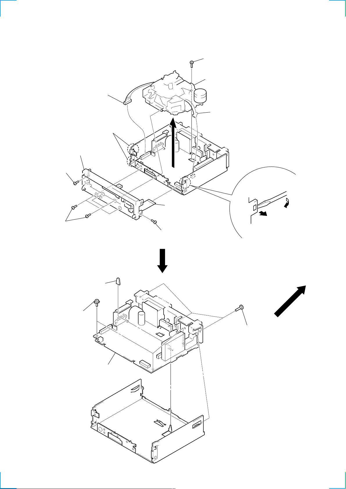
SECTION 2
DISASSEMBLY
Note: Follow the disassembly procedure in the numerical order given.
MECHANISM DECK (MG-25G-136)
6 connector
(CN302)
2 two claws
4 sub panel ass’y
1 screw (PTT2.6 × 8)
1 four screws
(PTT2.6 × 8)
3 connector
(CN701)
1 screw (PTT2.6 × 8)
7 screw (PTT2.6 × 6)
8 mechanism deck
(MG-25G-136)
5 flexible board
(CN301)
2 claw
MAIN BOARD
2 three ground point
screws
3 rubber cap (25)
1 three screws
(PTT2.6 × 8)
4 main board
8
Page 9
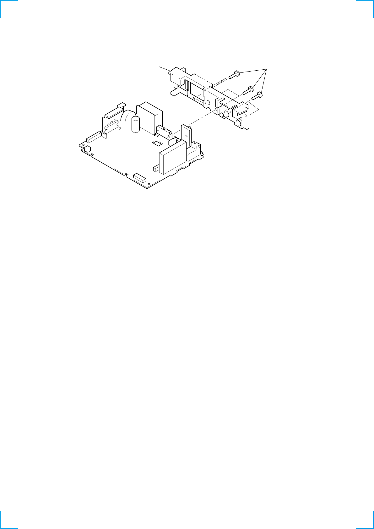
HEAT SINK
)
2 heat sink
1 six screws
(PTT2.6 × 8
9
Page 10
SECTION 3
ASSEMBLY OF MECHANISM DECK
Note: Follow the assembly procedure in the numerical order given.
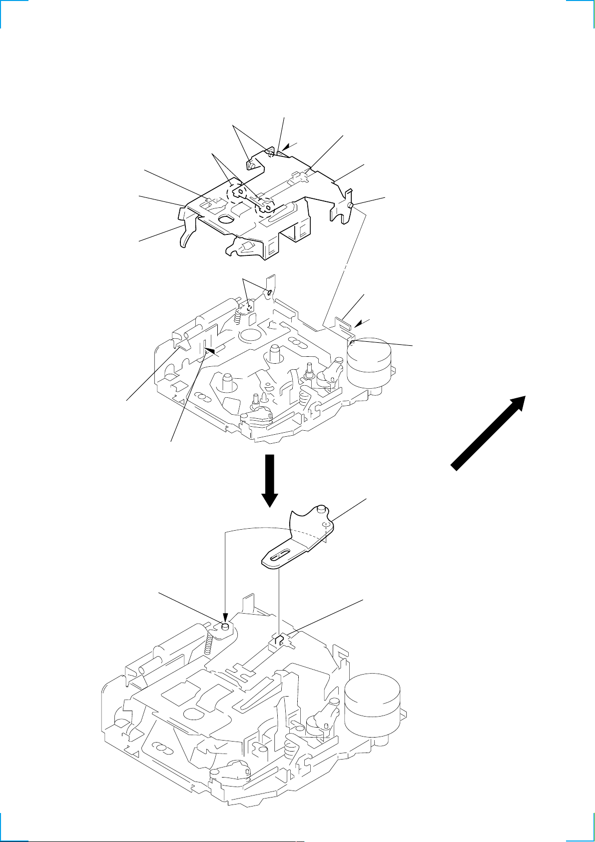
HOUSING
5 Fit projection on C part.
2 Install the hanger onto
two claws of the housing.
4 Fit claw on B part.
7 Hold the hanger by bending the claw.
1 Install the catch to the hanger.
hanger
3 Put the housing
under A part.
housing
A part
6 Fit projection on D part.
C part
8 Hold the hanger by
bending the claw.
D part
B part
ARM (SUCTION)
2 Move the arm (suction) in the arrow
direction and fit on projection.
projection
1 Fit the arm (suction) on the shaft.
10
Page 11
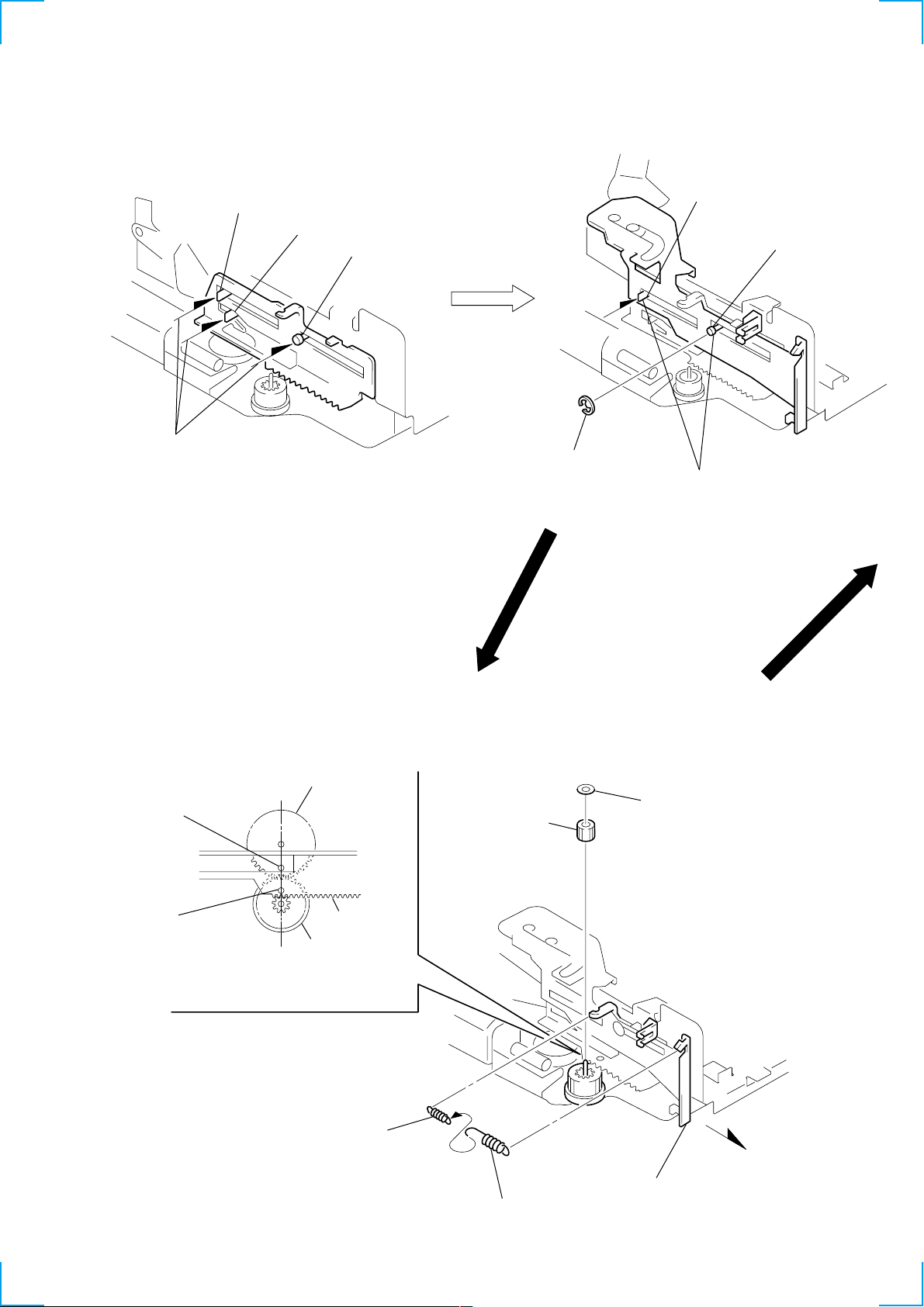
LEVER (LDG-A) / (LDG-B)
)
shaft A
1 Fit the lever (LDG-A) on
shafts A – C and install it.
shaft B
shaft C
shaft A
shaft B
3 type-E stop ring 2.0
2 Fit the lever (LDG-B) on
shafts A and B and
install it.
GEAR (LDG-FT)
hole
hole
gear (LDG-D)
6 polyethylene washer
5 gear (LDG-FT)
lever (LDG-A)
gear (LDG-FB)
4 Align hole in the gear (LDG-D)
with hole the lever (LDG-A).
1
2 tension spring (LD-2)
2 tension spring (LD-1)
3 Move the lever (LDG-B
in the arrow direction.
11
Page 12
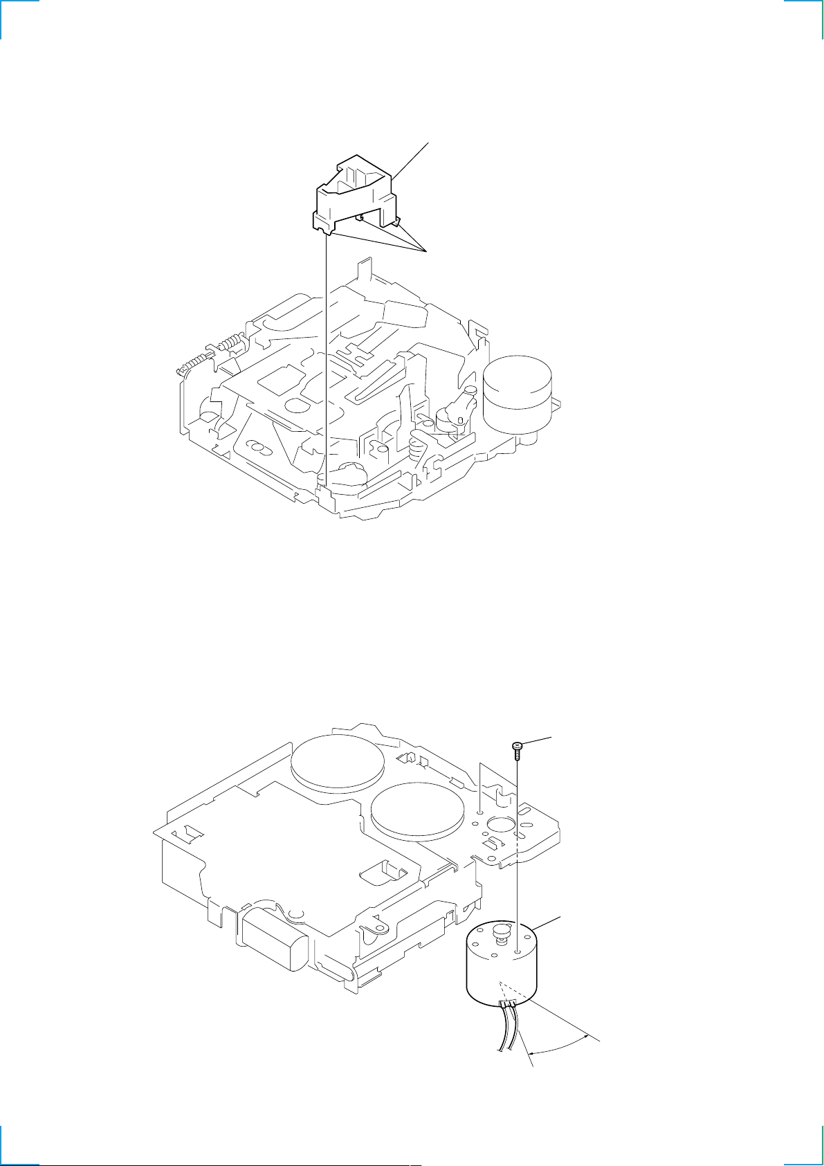
GUIDE (C)
2 guide (C)
1 three claws
MOUNTING POSITION OF CAPSTAN/REEL MOTOR (M901)
two precision screws
(P2 × 2)
capstan/reel motor
(M901)
12
30˚
Page 13

SECTION 4
r
MECHANICAL ADJUSTMENTS
SECTION 5
ELECTRICAL ADJUSTMENTS
1. Clean the follo wing parts with a denatured-alcohol-moistened
swab:
playback head pinch roller
rubber belt capstan
idler
2. Demagnetize the playback head with a head demagnetizer.
3. Do not use a magnetized screwdriver for the adjustments.
4. After the adjustments, apply suitable locking compound to the
parts adjusted.
5. The adjustments should be performed with the power supply
voltage unless otherwise noted.
• T orque Measurement
Mode Torque Meter Meter Reading
Forward CQ-102C (30 – 65 g•cm)
Forward
Back Tension
Reverse CQ-102RC (30 – 65 g•cm)
Reverse
Back Tension
FF, REW CQ-201B (60 – 200 g•cm)
CQ-102C (0.5 – 4.5g•cm)
CQ-102RC (0.5 – 4.5g•cm)
2.95 – 6.37 mN•m
(0.42 – 0.90 oz•inch)
0.05 – 0.44 mN•m
(0.01 – 0.06 oz•inch)
2.95 – 6.37 mN•m
(0.42 – 0.90 oz•inch)
0.05 – 0.44 mN•m
(0.01 – 0.06 oz•inch)
5.89 – 19.61 mN•m
(0.83 – 2.78 oz•inch)
TAPE DECK SECTION
0 dB=0.775 V
Tape Speed Adjustment
Setting:
speed checker
or
test tape
WS-48A
(3 kHz, 0 dB)
set
AUDIO OUT jack (CNJ151)
frequency counte
10 kΩ
+–
Procedure:
1. Put the set into the FWD PB mode.
2. Adjust adjustment resistor for inside capstan motor so that the
reading on the speed checker or frequency counter becomes in
specification.
Specification: Constant speed
Speed checker Frequency counter
–1.5 to +2.5% 2,955 to 3,075 Hz
Adjustment Location:
– SET UPPER VIEW –
• T ape Tension Measurement
Mode Tension Meter Meter Reading
more than 8.83 mN•m
Forward CQ-403A (more than 90 g)
(more than 3.18 oz)
more than 8.83 mN•m
Reverse CQ-403R (more than 90 g)
(more than 3.18 oz)
Tape Speed Adjustment
TUNER SECTION
Tuner section adjustments are done automatically in this set.
13
Page 14

MEMO
14
Page 15

SECTION 6
DIAGRAMS
6-1. NOTE FOR PRINTED WIRING BOARDS AND SCHEMATIC DIAGRAMS
Note on Printed Wiring Board:
• X : parts extracted from the component side.
• Y : parts extracted from the conductor side.
• b : Pattern from the side which enables seeing.
(The other layers' patterns are not indicated.)
Caution:
Pattern face side: Parts on the pattern face side seen from
(Conductor Side) the pattern face are indicated.
Parts face side: Parts on the parts face side seen from
(Component Side) the parts face are indicated.
Note on Schematic Diagram:
• All capacitors are in µF unless otherwise noted. pF: µµF
50 WV or less are not indicated except for electrolytics
and tantalums.
• All resistors are in Ω and 1/
specified.
f
•
• C : panel designation.
• U : B+ Line.
• Power voltage is dc 14.4V and f ed with regulated dc power
• Voltages and waveforms are dc with respect to ground
• Voltages are taken with a V OM (Input impedance 10 MΩ).
• Waveforms are taken with a oscilloscope.
• Circled numbers refer to waveforms.
• Signal path.
: internal component.
supply from ACC and BATT cords.
under no-signal (detuned) conditions.
no mark : FM
( ) : MW/LW
〈〈 〉〉 : TAPE PLAYBACK
Voltage variations may be noted due to normal production tolerances.
Voltage variations may be noted due to normal production tolerances.
F : FM
f : MW/LW
E : TAPE PLAYBACK
4
W or less unless otherwise
• Waveforms
– MAIN Board –
1 IC51 5 (OSCI)
231 ns
2 IC501 ud (X1A)
2.6 Vp-p
3.2 Vp-p
– KEY Board –
1 IC901 y; (OSC)
2.6 Vp-p
26.4 µs
305 µs
3 IC501 od (X1)
272 ns
5.5 Vp-p
1515
Page 16

XR-4200R/4300R/4300RX
• Semiconductor
Location
Ref. No. Location
D51 I-11
D80 E-11
D90 G-12
D91 G-12
D92 F-12
D351 I-3
D501 I-8
D551 F-3
D552 F-2
D553 F-2
D554 F-3
D558 F-6
D571 D-5
D572 D-5
D581 F-3
D591 F-2
D601 J-3
D615 F-10
D616 F-10
D621 D-9
D622 D-9
D624 D-8
D653 I-9
D702 K-13
D705 K-13
D707 K-11
D708 J-13
D709 K-11
D710 K-13
D711 J-10
6-2. PRINTED WIRING BOARD – MAIN Board (Component Side) –
IC51 I-13
IC90 F-12
IC301 G-11
IC331 D-10
IC361 I-2
IC501 I-7
IC551 J-3
Q82 F-11
Q90 F-11
Q91 F-12
Q121 E-12
Q151 E-12
Q171 C-9
Q181 C-9
Q271 C-10
Q281 C-10
Q351 I-3
Q352 I-3
Q353 H-3
Q354 H-2
Q551 H-8
Q571 D-6
Q581 G-3
Q582 F-4
Q583 F-7
Q591 G-2
Q592 G-3
Q602 K-2
Q621 D-9
Q622 D-8
Q701 K-2
1616
Page 17

6-3. PRINTED WIRING BOARD – MAIN Board (Conductor Side) –
XR-4200R/4300R/4300RX
CN601
(FRONT VIEW)
1514121311109
6
7
12453
1514121311109
6
7
8
8
GRN/BLK
WHT/BLK
GRY/BLK
VIO/BLK
BRU
BRU/WHT
VIO
GRY
WHT
GRN
BLU
RED
F901
REAR RCH (+)
FRONT RCH (+)
FRONT LCH (+)
REAR LCH (+)
REAR LCH (–)
FRONT LCH (–)
FRONT RCH (–)
REAR RCH (–)
4300R/
ATT
4300RX
AMP REM
ANT REM
ACC
12453
BLK
GND
YEL
BATT
• Semiconductor
Location
Ref. No. Location
D352 I-2
D610 C-4
D611 C-5
D613 C-5
D614 C-5
D701 K-10
D703 K-9
D704 K-10
D706 K-10
D712 K-10
D721 C-6
D722 C-7
D723 D-6
D724 C-6
D731 C-6
D732 D-7
D733 C-5
D734 C-6
D781 D-4
(Page 22)
IC611 B-8
IC671 F-1
Q601 J-2
1717
Page 18

XR-4200R/4300R/4300RX
6-4. SCHEMATIC DIAGRAM – MAIN Board (1/2) – • See page 15 for Waveforms. • See page 23 for IC Block Diagrams.
1818
Page 19

6-5. SCHEMATIC DIAGRAM – MAIN Board (2/2) – • See page 23 for IC Block Diagrams.
XR-4200R/4300R/4300RX
(Page 22)
1919
Page 20

XR-4200R/4300R/4300RX
6-6. PRINTED WIRING BOARD – KEY Board –
• Semiconductor
Location
Ref. No. Location
IC951 C-5
LED901 A-2
LED902 C-2
LED903 C-3
LED904 A-3
LED910 B-12
LED911 B-12
LED912 A-12
LED913 A-5
LED914 B-5
LED915 B-5
• Semiconductor
Location
Ref. No. Location
D901 A-11
D902 B-10
D903 B-10
D904 B-10
D951 C-4
D952 B-6
IC901 B-8
Q901 A-3
Q902 A-3
(Page 22)
2020
Page 21

6-7. SCHEMATIC DIAGRAM – KEY Board – • See page 15 for Waveforms.
(Page
22)
XR-4200R/4300R/4300RX
2121
Page 22

XR-4200R/4300R/4300RX
6-8. PRINTED WIRING BOARD – SUB Board – 6-9. SCHEMATIC DIAGRAM – SUB Board –
(Page 21)
(Page 20)
(Page 19)
(Page 17)
2222
Page 23

• IC Block Diagrams
– MAIN BOARD –
IC51 SAA6588T/V2-118
LVIN
20
MULTI
PATH
DETECTOR
2
1
MRO
MPTH
CIN
19
CLOCKED
COMPARATOR
RDS/RDBS
DEMODULATOR
TEST
CONTROL
3
TCON
SCOUT
18
BAND-PASS FILTER
RDS/RDBS
OSCILLATOR
& CLOCK
4 5
OSCO
57kHz
8th ORDER
DECODER
OSCI
6
VSSD
17
CLOCK
DATA
7
VDDD
VREF
MPX
SIGNAL QUALITY
DECODER
445
INTERFACE
REGISTER
8
DAVN
VDDA
VSSA
14
15
POWER SUPPLY
& RESET
CLOCK
DATA
AFIN
1316
IIC BUS SLAVE
TRANSCEIVER
9 10
SCL
SDA
PAUSE
DETECTOR
MAD
PSWN
11
12
IC301 CXA2509AQ-T4
PBEQ2
PBOUT2
GND
282930
27
120µ/70µ
+
–
PBFB2
PBRIN2
PBREF2
PBFIN2
VCT
PBGND
PBFIN1
PBREF1
PBRIN1
PBFB1
31
32
33
34
35
VCT
36
37
38
39
40
1
PBEQ1
X1
F2
+
F1
X1
–
+
120µ/70µ
345 6 7 8 9
2
VCC
PBOUT1
TAPEIN2
AUXIN1
TAPEIN1
AUXIN2
T2
LPF
T1
MSLPF
25
NR BIAS
TAPE/AUX
TAPE EQ
FWD/RVS
VCC
+
–
F3
–
+
LINEOUT1
DIREF
24dB
NC
24
+
NC
LINEOUT2
24dB
–
10
G2FB
NC
MSSW
NC
21222326
MS
MODE
DETECT
MS ON/
OFF
20
19
18
17
16
15
14
13
12
11
MSMODE
DRSW
TAPESW
INSW
NC
NC
MSOUT
DGND
MSTC
G1FB
23
Page 24

IC331 TDA7402TR
34
ACINLF
35
SWINR
36
SWINL
37
ACOUTR
38
ACOUTL
39
CREF
LP
HP
BASS
TREBLE
VOLUME
SOFTMUTE
LOUDNESS
MUX
40
+
IN-GAIN
+AUTO ZERO
MAIN SOURCE
SELECTOR
MD1
41
MD1G
MD2
MD2G
MAIN
42
43
PHONO
44
MAIN CH0 AUX
1 2 3 4 5 6 7 8 9 10 11
SEL
SER
ACINLR
ACINRF
ACINRR
33 32 31 30 29 28 27 26 25
LOUDNESS
IN-GAIN
MUTE
SELECTOR
FD2L–
FD2R+
FD2R–
FRONT
REAR
SW
FM
AM
AM
VOICE
BANDPASS
COMPANDER
MIXING
SELECTOR
MULTIPLEXER
FD1L+
FD1L–
ACIN
MAIN
INPUT
FD1R+
FD1R–
OUTPUT
SELECTOR
SECOND
SECOND SOURCE
FD2L+
MONOFADER
DIGITAL CONTROL IIC-BUS
OUTLF
MONOFADER
OUTLR
MIXER
MONO-
FADER
BEEP
AM/FM
NOISE BLANKER
OUTRF
OUTRR
MONOFADER
HIGH-CUT
S&H
25kHz
LP
DEMODULATOR
+STEREO ADJUST
+STEREO BLAND
PILOT
CANCELATION
OUTSWL
MONO-
FADER
SUBWOOFER
+PHASE
CONTROL
PIL DET
PLL
OUTSWR
MONO-
FADER
MULTIPATH
CONVERTER
SUPPLY
PULSE
FORMER
QUAL
DETECTOR
D/A
80kHz
24 23
LP
OUTSSL
OUTSSR
22
21
20
19
18
17
16
15
14
13
12
VDD
SCL
SDA
GND
SM
QUAL
MPOUT
MPIN
LEVEL
MPX
AMIF
24
Page 25

IC361 LB1930M-TLM
VCC
1
BUFFER
NC
2
IN1
IN2
S-GND
3
4
BUFFER
5
CONTROL
CIRCUIT
IC671 BA4908-V3
MOTOR
DRIVE
CIRCUIT
REGULATOR
NC
10
OUT1
9
8
NC
7
OUT2
P-GND
6
2 3
1
NC
TUNER8.7 ANT SW
–
+
4
STB
TUNER5.6 SW
OVER VOLTAGE
PROTECT
5 6 7 8 9
ANT
VCC
AMP
VDD5.6V
COM8.7V
–
+
10
TUNER5.6V
–
+
11
TUNER8.7V
–
+
12
GND
25
Page 26

6-10. IC PIN FUNCTION DESCRIPTION
• MAIN BOARD IC501 MB90574BPMT-G-267-BND (SYSTEM CONTROLLER)
Pin No. Pin Name I/O Description
1
2
3 BUS-ON
4 to 6
7
8VCC—
9 E2P SIO
10 E2P CKO
11 SYSRST O
12 DOORSW I
13 LCD SO
14 LCD CKO
15 LCD CE
16
17 UNISI
18 UNISO
19 UNICKO
20 UNICKI
21
22
23
24
25 to 28
29 DOOR-IND
30
31
32 NS MASK O
33
34 C —
35 AD-ON
36 RE-IN0
37 RE-IN1
38 DVCC —
39 DVSS —
40, 41
42 AVCC —
43 AVRH
44 AVRL
45 AVSS —
TU-ON O
ANT CUT O
NCO
ILL-ON O
BEEP O Beep sound drive signal output terminal
CD/MD
FLASH-W
NCO
SIRCS
NCO
IFWIDTH
NCO
VSS
NCO
Tuner system power supply on/off control signal output to the BA4908 (IC671)
“H”: tuner power on
Tuner system power supply on/off control signal output terminal “H”: tuner power on
Not used (open)
O Bus on/off control signal output terminal “L”: bus on Not used (fixed at “H” in this set)
O
Not used (open)
Power on/off control signal output of the illumination LED and liquid crystal display driver
(IC901) “H”: power on
Power supply terminal (+5V)
I/O Two-way data bus with the FM/AM tuner unit (TU1)
I/O Two-way data bus with the FM/AM tuner unit (TU1)
Reset signal output terminal “L”: reset Not used (fixed at “H” in this set)
Front panel open/close detection signal input “L” is input when the front panel is closed
O Serial data output to the liquid crystal display driver (IC901)
O Serial data transfer clock signal output to the liquid crystal display driver (IC901)
O Chip enable signal output to the liquid crystal display driver (IC901) “H” active
I Serial data input terminal Not used (fixed at “L” in this set)
O Serial data output terminal Not used (fixed at “L” in this set)
O Serial data transfer clock signal output terminal Not used (fixed at “L” in this set)
I Serial data transfer clock signal input terminal Not used (fixed at “L” in this set)
I
CD/MD selection signal input terminal Not used (fixed at “L” in this set)
Internal flash memory data write mode detection signal input terminal “L”: data write mode
I
Not used (fixed at “H” in this set)
O
Not used (open)
Sircs remote control signal input form the remote control receiver (IC951)
I
Used for XR-4300R/4300RX
O
Not used (open)
LED drive signal output of the door indicator (LED801) “H”: LED on
O
“H” is output to turn on LED when front panel is opened
I
IF band detection signal input terminal Not used (open)
O
Not used (open)
Discharge control signal output for the noise detection circuit “H”: discharge
—
Ground terminal
Connected to coupling capacitor for the power supply
A/D converter power control signal output terminal
O
When the KEYACK (pin uh) that controls reference voltage power for key A/D conversion input
is active, “L” is output from this terminal to enable the input
I
Dial pulse input of the rotary encoder (RE901)
(for VOLUME/BASS/TREBLE/BALANCE/FADER control)
I
Power supply terminal (+5V) (for D/A converter)
Ground terminal (for D/A converter)
O
Not used (open)
Power supply terminal (+5V) (for A/D converter)
I Reference voltage (+5V) input terminal (for A/D converter)
I Reference voltage (0V) input terminal (for A/D converter)
Ground terminal (for A/D converter)
26
Page 27

Pin No. Pin Name I/O Description
Key input terminal (A/D input) (LSW901 to LSW907, S901 to S904)
46 KEYIN0
47 KEYIN1
48 RC-IN0
49 DSTSEL I
50 QUALITY I
51 FMAGC I
52 MPTH
53
54 VCC —
55 RAMBU I
56 TUNATT O
57 VOL ATT O
58 ATT
59 AMP ON O
60 AMP ATT
61 COLSW I
62 COLSEL I
63 VSS —
64 DAVN I
65 FILE
66 TEXT
67 NOSESW I
68, 69 NCO
70 I2C SIO I/O
71 I2C CKO O
72 NCO O
73 X1A O
74 X0A I
75
76 KEYACK
77 BU-IN
78 ILL IN
79
VSM I
NCO
TEL-ATT I
I
OFF, SOURCE, SOUND, MENU, PTY DSPL, MODE o, ENTER, SEEK/AMS . m –,
PRST+, SEEK/AMS > M +, PRST- keys input
Key input terminal (A/D input) (LSW801, LSW909 to LSW917)
I
Z, D-BASS, TA, AF, 6, 5, 4, 3, SHIFT 2, REP 1 keys input
I Rotary remote commander key input terminal (A/D input)
Destination setting terminal (fixed at “L”)
Noise level detection signal input at SEEK mode (A/D input)
FM AGC level detection signal input from the FM/AM tuner unit (TU1) (A/D input)
I Multi-path detection signal input from the RDS decoder (IC51)
FM and AM signal meter voltage detection input from the FM/AM tuner unit (TU1)
(A/D input)
Power supply terminal (+5V)
Internal RAM reset detection signal input terminal
Input terminal to check that RAM data are not destroyed due to low voltage
This checking is made within 100 msec after reset Fixed at “H” in this set
Muting on/off control signal output of the FM and AM tuner signal “H”: muting on
Muting control signal output to the electrical volume (IC331)
Volume minimum: “∞” output (“H” active)
O Audio line muting on/off control signal output terminal “H”: muting on
Standby on/off control signal output to the power amplifier (IC611)
“L”: standby mode, “H”: amp on
O Muting on/off control signal output to the power amplifier (IC611) “L”: muting on
Setting terminal for the illumination color “L”: 2 colors, “H”: 1 color
(fixed at “L” in XR-4200R/4300R, fixed at “H” in XR-4300RX)
Setting terminal for the illumination color “L”: amber, “H”: green
Ground terminal
Data transmit completed detect signal input from the RDS decoder (IC51) “H” active
I Setting terminal for the custom file (fixed at “L” in this set)
I Setting terminal for the CD text (fixed at “L” in this set)
Front panel block remove/attach detection signal input terminal
“L”: front panel is attached
O Not used (open)
Two-way data bus with the RDS decoder (IC51), electrical volume (IC331) and FM/AM tuner
unit (TU1)
Bus clock signal output to the RDS decoder (IC51), electrical volume (IC331) and FM/AM tuner
unit (TU1)
Not used (open)
Sub system clock output terminal (32.768 kHz)
Sub system clock input terminal (32.768 kHz)
O
Not used (open)
Input of acknowledge signal for the key entry Acknowledge signal is input to accept function
I
and eject keys in the power off status On at input of “H”
Battery detect signal input from the SONY bus interface (IC701) and battery detect circuit
I
“L” is input at low voltage
Auto dimmer control illumination line detection signal input terminal
I
“L” is input at dimmer detection Fixed at “L” in this set
Telephone muting signal input terminal At input of “H”, the signal is attenuated by –20 dB
Used for XR-4300R/4300RX
27
Page 28

Pin No. Pin Name I/O Description
80
81 TESTIN
82 ACC IN
83
84
85 RC-IN1
86 HSTX I
87 MD2 I
88, 89 MD1, MD0 I
90 RESET I
91 VSS —
92 X0
93 X1
94 VCC —
95 to 97 NCO O
98 DIMSEL I
99 TAPE/CD I
100, 101 NCO O
102 MTLIN I
103 AMSIN I
104 REEL I
105 POS0 I
106 POS1 I
107 POS2 I
108 POS3 I
109 LM-EJ O
110 LM-LOD O
111 CM-ON O
112 TAPEON O
113 N-ROUT O
114 AMSON O
115 MTLON I/O
116 DOLON I/O
117 TAPE ATT O
NCO
NCO
LOCKIN
O
Not used (open)
I Setting terminal for the test mode “L”: test mode, Normally: fixed at “H”
I Accessory detect signal input terminal “L”: accessory on
O
Not used (open)
I
MD lock detection signal input terminal Not used (open)
I Rotary remote commander shift key input terminal “L”: shift
Hardware standby input terminal “L”: hardware standby mode Reset signal input in this set
Setting terminal for the CPU operational mode (fixed at “L” in this set)
Setting terminal for the CPU operational mode (fixed at “H” in this set)
System reset signal input from the reset signal generator (IC551) and reset switch (S503)
“L”: reset “L” is input for several 100 msec after power on, then it changes to “H”
Ground terminal
I Main system clock input terminal (3.68 MHz)
O Main system clock output terminal (3.68 MHz)
Power supply terminal (+5V)
Not used (open)
Dimmer selection signal input terminal (fixed at “H” in this set)
Tape/CD selection signal input terminal “L”: CD, “H”: tape (fixed at “H” in this set)
Not used (open)
Auto metal detection signal input terminal “L”: auto metal (fixed at “H” in this set)
Whether a music is present or not from CXA2509AQ (IC301) is detected at auto music sensor
“L”: music is present, “H”: music is not present
Rotation detect signal input from supply reel sensor and take-up reel sensor on the deck
mechanism
Tape position (EJECT/FF/REW/
REV/FWD mode) detect input from
the tape operation switch on the deck
mechanism
Motor drive signal output to the loading/tape operation motor drive (IC361) “H” active
(For the eject direction and reverse side operation) *1
Motor drive signal output to the loading/tape operation motor drive (IC361) “H” active
(For the loading direction and forward side operation) *1
Capstan/reel motor (M901) drive signal output terminal “H”: motor on
Tape system power supply on/off control signal output terminal “H”: tape on
Forward/reverse direction control signal output to the CXA2509AQ (IC301)
“L”: forward direction, “H”: reverse direction
Tape auto music sensor control signal output to the CXA2509AQ (IC301)
“L” is output to lower the gain for audio level at FF/REW mode
METAL control in/out terminal
At initial mode: auto/manual mode selection input of METAL function (manual at “L” input)
At manual mode: METAL on/off control signal output terminal (METAL on at “H” output)
At auto mode: input at MTLIN (pin <z/x )
Dolby control in/out terminal
At initial mode: valid/invalid selection input of dolby function (valid at “L” input)
At normal mode: dolby on/off control signal output terminal (dolby on at “H” output)
Not used this function (fixed at “H”)
Tape muting on/off control signal output to the CXA2509AQ (IC301) “H”: muting on
Active at ATA, FF/REW mode
POS0: “L”: EJECT mode, “H”: others mode
POS1: “L”: FF and FWD mode, “H”: others mode
POS2: “L”: REW mode, “H”: others mode
POS3: “L”: REV and EJECT mode, “H”: others mode
28
Page 29

Pin No. Pin Name I/O Description
118 NCO O
119 VSS
120 POWON
Not used (open)
—
Ground terminal
O Main system power supply on/off control signal output to the BA4908 (IC671) “H”: power on
Mode
Terminal
LM-LOD (pin <zz/ )
LM-EJ (pin <z/. )
*1 Loading/tape operation motor control
STOP
“L”“H”“L”“H”
“L”“L”“H”“H”
LOADING/
FORWARD
EJECT/
REVERSE
BRAKE
29
Page 30

SECTION 7
EXPLODED VIEWS
NOTE:
• -XX and -X mean standardized parts, so they
may have some difference from the original
one.
• Color Indication of Appearance Parts
Example:
KNOB, BALANCE (WHITE) . . . (RED)
↑↑
Parts Color Cabinet's Color
(1) CHASSIS SECTION
13
8
not
supplied
10
9
7
#1
• Items marked “*” are not stocked since they
are seldom required for routine service. Some
delay should be anticipated when ordering
these items.
• The mechanical parts with no reference number in the exploded views are not supplied.
• Hardware (# mark) list and accessories and
packing materials are given in the last of the
electrical parts list.
#3
#1
12
MG-25G-136
20
21
11
6
2
5
14
F901
22
TU1
(4300R/4300RX)
A
(4200R)
A
#1
#5
18
15
15
#1
17
A
#1
#1
19
16
#2
#1
#2
Front panel ass’y
Ref. No. Part No. Description Remark
1 X-3378-397-1 PANEL ASSY, SUB
* 2 1-676-603-12 SUB BOARD
3 1-792-195-11 CABLE, FLEXIBLE FLAT
4 X-3377-621-2 LOCK ASSY
5 3-040-990-01 BUTTON (EJECT) (Z)
6 3-935-003-01 SPRING, TORSION
7 3-027-437-12 DOOR, CASSETTE
8 X-3376-699-2 GEAR ASSY
9 3-713-786-51 SCREW +P 2X3
10 3-030-909-02 DAMPER, OIL
* 11 3-040-994-01 CHASSIS
* 12 3-040-995-01 COVER
13 3-915-923-01 SCREW, GROUND POINT
14 1-782-381-11 CORD (WITH CONNECTOR) (ISO P&S)
1
#4
#1
(POWER)
4
3
Ref. No. Part No. Description Remark
15 1-777-989-21 CORD (WITH CONNECTOR) (AMP REM)
(4200R)
15 1-777-989-41 CORD (WITH CONNECTOR) (AMP REM/ATT)
(4300R/4300RX)
16 3-012-859-01 CAP (25), RUBBER
* 17 3-045-878-01 PLATE (TU), GROUND
* 18 3-045-877-01 CUSHION (TU)
* 19 A-3326-172-A MAIN BOARD, COMPLETE (4200R)
* 19 A-3326-173-A MAIN BOARD, COMPLETE (4300R)
* 19 A-3326-184-A MAIN BOARD, COMPLETE (4300RX)
* 20 3-040-998-01 BRACKET (IC)
* 21 3-041-262-01 HEAT SINK (REG/XR)
* 22 3-041-014-01 HEAT SINK (IS02P)
F901 1-532-877-11 FUSE (BLADE TYPE) (AUTO FUSE) (10A)
TU1 A-3220-738-A TUNER UNIT (TUX-020)
30
Page 31

(2) FRONT PANEL SECTION
60
59
63
#8
68
not supplied
(KEY board)
67
58
57
56
55
52
69
53
51
Ref. No. Part No. Description Remark
51 3-040-988-01 BUTTON (1-6) (1. 2. 3. 4. 5. 6)
52 3-040-987-01 BUTTON (OFF)
53 3-041-006-01 BUTTON (AF/TA)
54 3-041-005-11 BUTTON (D) (D-BASS)
55 3-037-267-01 SPRING (OPEN)
66
65
64
LCD901
54
Ref. No. Part No. Description Remark
64 1-694-660-11 CONDUCTIVE BOARD, CONNECTION
* 65 3-041-371-01 SHEET (REFLECTOR)
* 66 3-040-993-01 PLATE (LCD), LIGHT GUIDE
* 67 3-040-992-01 HOLDER (LCD)
68 X-3378-398-1 PANEL ASSY, FRONT BACK
56 3-040-989-01 BUTTON (OPEN)
57 3-040-985-01 BUTTON (DIR/ENTER)
(DSPL. MODE o. ENTER)
58 3-040-986-01 BUTTON (MENU/SOUND)
59 3-040-980-01 BUTTON (SOURCE)
60 3-040-981-01 KNOB(VOL)
* 63 3-040-997-01 PLATE (LCD), GROUND
69 X-3378-577-1 PANEL SUB ASSY (4300RX)
69 X-3378-587-1 PANEL SUB ASSY (4300R)
69 X-3378-588-1 PANEL SUB ASSY (4200R)
LCD901 1-803-906-21 DISPLAY PANEL, LIQUID CRYSTAL
(4200R/4300R)
LCD901 1-803-906-41 DISPLAY PANEL, LIQUID CRYSTAL (4300RX)
31
Page 32

(3) MECHANISM DECK SECTION
(MG-25G-136)
160
159
153
154
#6
155
158
152
156
157
168
A
A
161
163
HP901
162
M901
164
not supplied
#7
168
166
151
Ref. No. Part No. Description Remark
151 A-3291-667-A CLUTCH (FR) ASSY
* 152 3-019-130-01 LEVER (LDG-A)
* 153 3-019-131-01 LEVER (LDG-B)
154 3-020-539-01 SPRING (LD-1), TENSION
155 3-020-540-01 SPRING (LD-2), TENSION
156 3-020-542-01 GEAR (LOADING FT)
157 3-341-753-11 WASHER, POLYETHYLENE
158 3-020-533-01 HOUSING
* 159 3-020-532-01 ARM (SUCTION)
160 3-020-534-01 HANGER
32
167
165
Ref. No. Part No. Description Remark
161 3-933-346-01 CATCHER
162 3-933-344-01 GUIDE (C)
163 3-014-798-01 SCREW (HEAD), SPECIAL
164 3-364-151-01 WASHER
165 A-3220-610-A MECHANISM DECK ASSY
166 3-017-302-01 BELT (25)
167 3-936-853-01 FLYWHEEL (F)
168 3-701-437-21 WASHER
HP901 1-500-196-21 HEAD, MAGNETIC (PLAYBACK)
M901 A-3291-665-A MOTOR ASSY, MAIN (CAPSTAN/REEL)
Page 33

SECTION 8
ELECTRICAL PARTS LIST
KEY
NOTE:
• Due to standardization, replacements in the
parts list may be different from the parts specified in the diagrams or the components used
on the set.
• -XX and -X mean standardized parts, so they
may have some difference from the original
one.
• RESISTORS
All resistors are in ohms.
METAL: Metal-film resistor.
METAL OXIDE: Metal oxide-film resistor.
F: nonflammable
Ref. No. Part No. Description Remark Ref. No. Part No. Description Remark
KEY BOARD
**********
1-694-660-11 CONDUCTIVE BOARD, CONNECTION
* 3-040-992-01 HOLDER (LCD)
* 3-040-993-01 PLATE (LCD), LIGHT GUIDE
* 3-040-997-01 PLATE (LCD), GROUND
* 3-041-371-01 SHEET (REFLECTOR)
< CAPACITOR >
C951 1-164-004-11 CERAMIC CHIP 0.1uF 10% 25V
C952 1-163-037-11 CERAMIC CHIP 0.022uF 10% 25V
C953 1-163-251-11 CERAMIC CHIP 100PF 5% 50V
C954 1-164-004-11 CERAMIC CHIP 0.1uF 10% 25V
C955 1-164-004-11 CERAMIC CHIP 0.1uF 10% 25V
C956 1-164-489-11 CERAMIC CHIP 0.22uF 10% 16V
< CONNECTOR >
CN901 1-794-065-21 PLUG, CONNECTOR 14P
< DIODE >
D901 8-719-158-49 DIODE UDZ-TE-17-12B
D902 8-719-056-82 DIODE UDZ-TE-17-6.2B
D903 8-719-056-82 DIODE UDZ-TE-17-6.2B
D904 8-719-056-82 DIODE UDZ-TE-17-6.2B
D951 8-719-976-99 DIODE UDZ-TE-17-5.1B (4300R/4300RX)
D952 8-719-976-99 DIODE UDZ-TE-17-5.1B
< IC >
IC901 8-759-366-34 IC LC75824E
IC951 8-749-012-25 IC RS-170-TU (4300R/4300RX)
< LIQUID CRYSTAL DISPLAY >
LCD901 1-803-906-21 DISPLAY PANEL, LIQUID CRYSTAL
LCD901 1-803-906-41 DISPLAY PANEL, LIQUID CRYSTAL (4300RX)
< LED >
LED901 8-719-061-16 LED CL-190SR-CD-T (ILLUMINATION)
LED901 8-719-078-15 LED CL-165Y/PG-D-T (ILLUMINATION)
• Items marked “*” are not stocked since they
are seldom required for routine service.
Some delay should be anticipated when ordering these items.
• SEMICONDUCTORS
In each case, u: µ, for example:
uA. . : µA. . uPA. . : µPA. .
uPB. . : µPB. . uPC. . : µPC. .
uPD. . : µPD. .
• CAPACITORS
uF: µF
• COILS
uH: µH
LED902 8-719-061-16 LED CL-190SR-CD-T (ILLUMINATION)
LED902 8-719-078-15 LED CL-165Y/PG-D-T (ILLUMINATION)
LED903 8-719-061-16 LED CL-190SR-CD-T (ILLUMINATION)
LED903 8-719-078-15 LED CL-165Y/PG-D-T (ILLUMINATION)
LED904 8-719-061-16 LED CL-190SR-CD-T (ILLUMINATION)
(4300R/4300RX)
(4200R/4300R)
(4300RX)
(4200R/4300R)
LED904 8-719-078-15 LED CL-165Y/PG-D-T (ILLUMINATION)
LED910 8-719-078-19 LED LWA673-R1S2*1 (LCD BACK LIGHT)
LED911 8-719-078-19 LED LWA673-R1S2*1 (LCD BACK LIGHT)
LED912 8-719-078-19 LED LWA673-R1S2*1 (LCD BACK LIGHT)
LED913 8-719-078-19 LED LWA673-R1S2*1 (LCD BACK LIGHT)
LED914 8-719-078-19 LED LWA673-R1S2*1 (LCD BACK LIGHT)
LED915 8-719-078-19 LED LWA673-R1S2*1 (LCD BACK LIGHT)
LSW901 1-771-610-11 SWITCH, TACTILE (WITH LED) (OFF)
LSW901 1-771-883-21 SWITCH, TACTILE (WITH LED) (OFF) (4300RX)
LSW902 1-762-620-21 SWITCH, KEY BOARD (WITH LED) (SOURCE)
LSW902 1-771-476-11 SWITCH, KEY BOARD (WITH LED) (SOURCE)
LSW903 1-762-620-21 SWITCH, KEY BOARD (WITH LED) (SOUND)
LSW903 1-771-476-11 SWITCH, KEY BOARD (WITH LED) (SOUND)
LSW904 1-762-620-21 SWITCH, KEY BOARD (WITH LED) (MENU)
LSW904 1-771-476-11 SWITCH, KEY BOARD (WITH LED) (MENU)
LSW905 1-762-620-21 SWITCH, KEY BOARD (WITH LED) (PTY DSPL)
LSW905 1-771-476-11 SWITCH, KEY BOARD (WITH LED) (PTY DSPL)
LSW906 1-762-620-21 SWITCH, KEY BOARD (WITH LED)
LSW906 1-771-476-11 SWITCH, KEY BOARD (WITH LED)
LSW907 1-762-620-21 SWITCH, KEY BOARD (WITH LED) (ENTER)
LSW907 1-771-476-11 SWITCH, KEY BOARD (WITH LED) (ENTER)
< SWITCH >
When indicating parts by reference
number, please include the board.
(4300RX)
(4200R/4300R)
(4300RX)
(4200R/4300R)
(4300RX)
(4200R/4300R)
(4200R/4300R)
(4200R/4300R)
(4300RX)
(4200R/4300R)
(4300RX)
(4200R/4300R)
(4300RX)
(4200R/4300R)
(4300RX)
(MODE o) (4200R/4300R)
(MODE o) (4300RX)
(4200R/4300R)
(4300RX)
33
Page 34

KEY
Ref. No. Part No. Description Remark
LSW909 1-762-737-11 SWITCH, KEYBOARD (LED) (D-BASS)
LSW910 1-762-620-21 SWITCH, KEY BOARD (WITH LED) (TA)
(4200R/4300R)
LSW910 1-771-476-11 SWITCH, KEY BOARD (WITH LED) (TA)
(4300RX)
LSW911 1-762-620-21 SWITCH, KEY BOARD (WITH LED) (AF)
(4200R/4300R)
LSW911 1-771-476-11 SWITCH, KEY BOARD (WITH LED) (AF)
(4300RX)
LSW912 1-771-610-11 SWITCH, TACTILE (WITH LED) (6)
(4200R/4300R)
LSW912 1-771-883-21 SWITCH, TACTILE (WITH LED) (6) (4300RX)
LSW913 1-771-610-11 SWITCH, TACTILE (WITH LED) (5)
(4200R/4300R)
LSW913 1-771-883-21 SWITCH, TACTILE (WITH LED) (5) (4300RX)
LSW914 1-771-610-11 SWITCH, TACTILE (WITH LED) (4)
(4200R/4300R)
LSW914 1-771-883-21 SWITCH, TACTILE (WITH LED) (4) (4300RX)
LSW915 1-771-610-11 SWITCH, TACTILE (WITH LED) (3)
(4200R/4300R)
LSW915 1-771-883-21 SWITCH, TACTILE (WITH LED) (3) (4300RX)
LSW916 1-771-610-11 SWITCH, TACTILE (WITH LED) (SHUF 2)
(4200R/4300R)
LSW916 1-771-883-21 SWITCH, TACTILE (WITH LED) (SHUF 2)
(4300RX)
LSW917 1-771-610-11 SWITCH, TACTILE (WITH LED) (REP 1)
(4200R/4300R)
LSW917 1-771-883-21 SWITCH, TACTILE (WITH LED) (REP 1)
(4300RX)
< TRANSISTOR >
Q901 8-729-904-75 TRANSISTOR DTD114EK-T-146
(4200R/4300R)
Q902 8-729-904-75 TRANSISTOR DTD114EK-T-146
(4200R/4300R)
< RESISTOR >
R901 1-216-647-11 METAL CHIP 680 0.5% 1/10W
R902 1-216-647-11 METAL CHIP 680 0.5% 1/10W
R903 1-216-647-11 METAL CHIP 680 0.5% 1/10W
R904 1-216-651-11 METAL CHIP 1K 0.5% 1/10W
R905 1-216-655-11 METAL CHIP 1.5K 0.5% 1/10W
Ref. No. Part No. Description Remark
R921 1-216-811-11 METAL CHIP 150 5% 1/16W
(4200R/4300R)
R922 1-216-807-11 METAL CHIP 68 5% 1/16W
(4200R/4300R)
R923 1-216-812-11 METAL CHIP 180 5% 1/16W
(4300RX)
R923 1-216-815-11 METAL CHIP 330 5% 1/16W
(4200R/4300R)
R924 1-216-809-11 METAL CHIP 100 5% 1/16W
(4200R/4300R)
R925 1-216-031-00 METAL CHIP 180 5% 1/10W
(4300RX)
R925 1-216-029-00 METAL CHIP 150 5% 1/10W
(4200R/4300R)
R926 1-216-807-11 METAL CHIP 68 5% 1/16W
(4200R/4300R)
R927 1-216-031-00 METAL CHIP 180 5% 1/10W
(4300RX)
R927 1-216-029-00 METAL CHIP 150 5% 1/10W
(4200R/4300R)
R928 1-216-807-11 METAL CHIP 68 5% 1/16W
(4200R/4300R)
R931 1-216-813-11 METAL CHIP 220 5% 1/16W
R932 1-216-813-11 METAL CHIP 220 5% 1/16W
R933 1-216-812-11 METAL CHIP 180 5% 1/16W
(4200R/4300R)
R933 1-216-813-11 METAL CHIP 220 5% 1/16W
(4300RX)
R934 1-216-808-11 METAL CHIP 82 5% 1/16W
(4200R/4300R)
R935 1-216-812-11 METAL CHIP 180 5% 1/16W
(4300RX)
R935 1-216-864-11 METAL CHIP 0 5% 1/16W
(4200R/4300R)
R936 1-216-809-11 METAL CHIP 100 5% 1/16W
(4200R/4300R)
R938 1-216-809-11 METAL CHIP 100 5% 1/16W
R939 1-216-821-11 METAL CHIP 1K 5% 1/16W
(4300RX)
R951 1-216-819-11 METAL CHIP 680 5% 1/16W
(4300R/4300RX)
R952 1-216-021-00 METAL CHIP 68 5% 1/10W
(4300R/4300RX)
R953 1-216-857-11 METAL CHIP 1M 5% 1/16W
R906 1-216-655-11 METAL CHIP 1.5K 0.5% 1/10W
R907 1-216-659-11 METAL CHIP 2.2K 0.5% 1/10W
R908 1-216-663-11 METAL CHIP 3.3K 0.5% 1/10W
R909 1-216-667-11 METAL CHIP 4.7K 0.5% 1/10W
R910 1-216-671-11 METAL CHIP 6.8K 0.5% 1/10W
R911 1-208-806-11 RES-CHIP 10K 2% 1/10W
R912 1-216-647-11 METAL CHIP 680 0.5% 1/10W
R913 1-216-647-11 METAL CHIP 680 0.5% 1/10W
R914 1-216-647-11 METAL CHIP 680 0.5% 1/10W
R915 1-216-651-11 METAL CHIP 1K 0.5% 1/10W
R916 1-216-655-11 METAL CHIP 1.5K 0.5% 1/10W
R917 1-216-655-11 METAL CHIP 1.5K 0.5% 1/10W
R918 1-216-659-11 METAL CHIP 2.2K 0.5% 1/10W
R919 1-216-663-11 METAL CHIP 3.3K 0.5% 1/10W
R920 1-216-667-11 METAL CHIP 4.7K 0.5% 1/10W
R921 1-216-810-11 METAL CHIP 120 5% 1/16W
34
R954 1-216-049-11 RES-CHIP 1K 5% 1/10W
R955 1-216-049-11 RES-CHIP 1K 5% 1/10W
R956 1-216-821-11 METAL CHIP 1K 5% 1/16W
R957 1-216-851-11 METAL CHIP 330K 5% 1/16W
R958 1-216-033-00 METAL CHIP 220 5% 1/10W
R970 1-216-815-11 METAL CHIP 330 5% 1/16W
R971 1-216-815-11 METAL CHIP 330 5% 1/16W
R972 1-216-864-11 METAL CHIP 0 5% 1/16W
R973 1-216-815-11 METAL CHIP 330 5% 1/16W
R975 1-216-815-11 METAL CHIP 330 5% 1/16W
R976 1-216-815-11 METAL CHIP 330 5% 1/16W
R977 1-216-815-11 METAL CHIP 330 5% 1/16W
R981 1-216-864-11 METAL CHIP 0 5% 1/16W
R999 1-216-864-11 METAL CHIP 0 5% 1/16W
(4300RX)
(4300RX)
Page 35

KEY MAIN
Ref. No. Part No. Description Remark
< ROTARY ENCODER >
RE901 1-475-014-11 ENCODER, ROTARY (VOLUME/BASS/TREBLE/
BALANCE/FADER CONTROL)
< SWITCH >
S901 1-771-884-21 SWITCH, TACTILE (WITH LED)
(SEEK/AMS - . m)
S902 1-771-884-21 SWITCH, TACTILE (WITH LED) (PRST +)
S903 1-771-884-21 SWITCH, TACTILE (WITH LED)
(SEEK/AMS + > M)
S904 1-771-884-21 SWITCH, TACTILE (WITH LED) (PRST -)
**************************************************************
* A-3326-172-A MAIN BOARD, COMPLETE (4200R)
* A-3326-173-A MAIN BOARD, COMPLETE (4300R)
* A-3326-184-A MAIN BOARD, COMPLETE (4300RX)
*********************
* 3-040-998-01 BRACKET (IC)
3-041-014-01 HEAT SINK (IS02P)
* 3-041-262-01 HEAT SINK (REG/XR)
7-685-647-79 SCREW +BVTP 3X10 TYPE2 N-S
7-685-793-09 SCREW +PTT 2.6X8 (S)
< CAPACITOR >
C1 1-162-918-11 CERAMIC CHIP 18PF 5% 50V
C2 1-107-826-11 CERAMIC CHIP 0.1uF 10% 16V
C3 1-126-933-11 ELECT 100uF 20% 16V
C4 1-162-968-11 CERAMIC CHIP 0.0047uF 10% 50V
C5 1-107-826-11 CERAMIC CHIP 0.1uF 10% 16V
C6 1-126-933-11 ELECT 100uF 20% 16V
C8 1-107-826-11 CERAMIC CHIP 0.1uF 10% 16V
(4200R)
C10 1-162-923-11 CERAMIC CHIP 47PF 5% 50V
C52 1-107-826-11 CERAMIC CHIP 0.1uF 10% 16V
C53 1-162-916-11 CERAMIC CHIP 12PF 5% 50V
C54 1-162-916-11 CERAMIC CHIP 12PF 5% 50V
C55 1-124-589-11 ELECT 47uF 20% 16V
C57 1-107-826-11 CERAMIC CHIP 0.1uF 10% 16V
C58 1-162-959-11 CERAMIC CHIP 330PF 5% 50V
C59 1-164-505-11 CERAMIC CHIP 2.2uF 16V
C60 1-164-739-11 CERAMIC CHIP 560PF 5% 50V
C61 1-162-966-11 CERAMIC CHIP 0.0022uF 10% 50V
C62 1-162-964-11 CERAMIC CHIP 0.001uF 10% 50V
C63 1-164-315-11 CERAMIC CHIP 470PF 5% 50V
C64 1-107-826-11 CERAMIC CHIP 0.1uF 10% 16V
C86 1-124-233-11 ELECT 10uF 20% 16V
C90 1-162-964-11 CERAMIC CHIP 0.001uF 10% 50V
C91 1-162-964-11 CERAMIC CHIP 0.001uF 10% 50V
C92 1-162-964-11 CERAMIC CHIP 0.001uF 10% 50V
C93 1-164-315-11 CERAMIC CHIP 470PF 5% 50V
C94 1-162-915-11 CERAMIC CHIP 10PF 0.5PF 50V
C95 1-125-891-11 CERAMIC CHIP 0.47uF 10% 10V
C96 1-165-176-11 CERAMIC CHIP 0.047uF 10% 16V
C98 1-107-826-11 CERAMIC CHIP 0.1uF 10% 16V
C100 1-162-915-11 CERAMIC CHIP 10PF 0.5PF 50V
C101 1-162-959-11 CERAMIC CHIP 330PF 5% 50V
C102 1-162-959-11 CERAMIC CHIP 330PF 5% 50V
C103 1-162-970-11 CERAMIC CHIP 0.01uF 10% 25V
Ref. No. Part No. Description Remark
C104 1-127-715-11 CERAMIC CHIP 0.22uF 10% 16V
C107 1-162-963-11 CERAMIC CHIP 680PF 10% 50V
C108 1-164-506-11 CERAMIC CHIP 4.7uF 16V
C109 1-163-227-11 CERAMIC CHIP 10PF 0.5PF 50V
C110 1-162-915-11 CERAMIC CHIP 10PF 0.5PF 50V
C112 1-162-915-11 CERAMIC CHIP 10PF 0.5PF 50V
C121 1-107-826-11 CERAMIC CHIP 0.1uF 10% 16V
C122 1-164-227-11 CERAMIC CHIP 0.022uF 10% 25V
C124 1-164-227-11 CERAMIC CHIP 0.022uF 10% 25V
C143 1-163-227-11 CERAMIC CHIP 10PF 0.50F 50V
(4300R)
C152 1-109-982-11 CERAMIC CHIP 1uF 10% 10V
C153 1-109-982-11 CERAMIC CHIP 1uF 10% 10V
C171 1-164-506-11 CERAMIC CHIP 4.7uF 16V
C173 1-127-715-11 CERAMIC CHIP 0.22uF 10% 16V
C174 1-163-251-11 CERAMIC CHIP 100PF 5% 50V
C181 1-164-506-11 CERAMIC CHIP 4.7uF 16V
C182 1-163-181-00 CERAMIC CHIP 100PF 5% 50V
C183 1-127-715-11 CERAMIC CHIP 0.22uF 10% 16V
C184 1-162-927-11 CERAMIC CHIP 100PF 5% 50V
C191 1-162-915-11 CERAMIC CHIP 10PF 0.5PF 50V
C200 1-162-915-11 CERAMIC CHIP 10PF 0.5PF 50V
C201 1-162-959-11 CERAMIC CHIP 330PF 5% 50V
C202 1-162-959-11 CERAMIC CHIP 330PF 5% 50V
C203 1-162-970-11 CERAMIC CHIP 0.01uF 10% 25V
C204 1-127-715-11 CERAMIC CHIP 0.22uF 10% 16V
C207 1-162-963-11 CERAMIC CHIP 680PF 10% 50V
C208 1-164-506-11 CERAMIC CHIP 4.7uF 16V
C209 1-163-227-11 CERAMIC CHIP 10PF 0.5PF 50V
C210 1-162-915-11 CERAMIC CHIP 10PF 0.5PF 50V
C212 1-162-915-11 CERAMIC CHIP 10PF 0.5PF 50V
C243 1-163-227-11 CERAMIC CHIP 10PF 0.5PF 50V
(4300R)
C271 1-164-506-11 CERAMIC CHIP 4.7uF 16V
C273 1-127-715-11 CERAMIC CHIP 0.22uF 10% 16V
C274 1-162-927-11 CERAMIC CHIP 100PF 5% 50V
C281 1-164-506-11 CERAMIC CHIP 4.7uF 16V
C282 1-163-181-00 CERAMIC CHIP 100PF 5% 50V
C283 1-127-715-11 CERAMIC CHIP 0.22uF 10% 16V
C284 1-163-251-11 CERAMIC CHIP 100PF 5% 50V
C291 1-162-915-11 CERAMIC CHIP 10PF 0.5PF 50V
C302 1-131-651-21 TANTALUM CHIP 10uF 20% 16V
C303 1-162-927-11 CERAMIC CHIP 100PF 5% 50V
C304 1-107-826-11 CERAMIC CHIP 0.1uF 10% 16V
C305 1-162-970-11 CERAMIC CHIP 0.01uF 10% 25V
C306 1-125-891-11 CERAMIC CHIP 0.47uF 10% 10V
C307 1-107-826-11 CERAMIC CHIP 0.1uF 10% 16V
C308 1-162-970-11 CERAMIC CHIP 0.01uF 10% 25V
C309 1-162-970-11 CERAMIC CHIP 0.01uF 10% 25V
C311 1-107-826-11 CERAMIC CHIP 0.1uF 10% 16V
C313 1-107-826-11 CERAMIC CHIP 0.1uF 10% 16V
C330 1-162-959-11 CERAMIC CHIP 330PF 5% 50V
C331 1-124-234-00 ELECT 22uF 20% 16V
C333 1-162-968-11 CERAMIC CHIP 0.0047uF 10% 50V
C335 1-107-823-11 CERAMIC CHIP 0.47uF 10% 16V
C336 1-107-826-11 CERAMIC CHIP 0.1uF 10% 16V
C337 1-124-584-00 ELECT 100uF 20% 10V
C341 1-162-970-11 CERAMIC CHIP 0.01uF 10% 25V
35
Page 36

MAIN
Ref. No. Part No. Description Remark
C343 1-124-233-11 ELECT 10uF 20% 16V
C351 1-164-156-11 CERAMIC CHIP 0.1uF 25V
C352 1-164-156-11 CERAMIC CHIP 0.1uF 25V
C353 1-162-970-11 CERAMIC CHIP 0.01uF 10% 25V
C355 1-124-234-00 ELECT 22uF 20% 16V
C356 1-126-934-11 ELECT 220uF 20% 16V
C357 1-164-156-11 CERAMIC CHIP 0.1uF 25V
C364 1-124-233-11 ELECT 10uF 20% 16V
C501 1-107-826-11 CERAMIC CHIP 0.1uF 10% 16V
C502 1-107-826-11 CERAMIC CHIP 0.1uF 10% 16V
C503 1-107-826-11 CERAMIC CHIP 0.1uF 10% 16V
C504 1-107-826-11 CERAMIC CHIP 0.1uF 10% 16V
C506 1-162-975-11 CERAMIC CHIP 24PF 5% 50V
C507 1-162-919-11 CERAMIC CHIP 22PF 5% 50V
C509 1-162-970-11 CERAMIC CHIP 0.01uF 10% 25V
C510 1-124-584-00 ELECT 100uF 20% 10V
C511 1-107-826-11 CERAMIC CHIP 0.1uF 10% 16V
C512 1-164-230-11 CERAMIC CHIP 220PF 5% 50V
C513 1-164-315-11 CERAMIC CHIP 470PF 5% 50V
C515 1-131-651-21 TANTALUM CHIP 10uF 20% 16V
C523 1-163-077-00 CERAMIC CHIP 0.1uF 50V
C551 1-125-701-11 DOUBLE LAYER 0.047F 5.5V
C552 1-126-933-11 ELECT 100uF 20% 16V
C553 1-162-970-11 CERAMIC CHIP 0.01uF 10% 25V
C571 1-126-163-11 ELECT 4.7uF 20% 50V
C582 1-162-964-11 CERAMIC CHIP 0.001uF 10% 50V
Ref. No. Part No. Description Remark
CN701 1-784-456-11 CONNECTOR, FFC/FPC 14P
< JACK >
CNJ151 1-774-698-11 JACK, PIN 2P (AUDIO OUT (LINE OUT))
< DIODE >
D51 8-719-067-56 DIODE MA112-TX
D80 8-719-422-12 DIODE UDZ-TE-17-3.9B
D90 8-719-073-01 DIODE MA111-TX
D91 8-719-073-01 DIODE MA111-TX
D92 8-719-976-99 DIODE UDZ-TE-17-5.1B
D351 8-719-977-22 DIODE UDZ-TE-17-9.1B
D352 8-719-911-19 DIODE 1SS119-25TD
D501 8-719-400-20 DIODE MA152WA-TX
D551 8-719-067-56 DIODE MA112-TX
D552 8-719-073-01 DIODE MA111-TX
D553 8-719-073-01 DIODE MA111-TX
D554 8-719-072-70 DIODE MA2ZD14001S0
D558 8-719-073-01 DIODE MA111-TX (4300R/4300RX)
D571 8-719-057-80 DIODE MA8180-M-TX
D572 8-719-420-14 DIODE MA8082-M (TX)
D581 8-719-056-93 DIODE UDZ-TE-17-18B
D591 8-719-056-84 DIODE UDZ-TE-17-7.5B
D601 8-719-056-88 DIODE UDZ-TE-17-11B
D610 8-719-970-02 DIODE 1SR139-400T-32
D611 8-719-970-02 DIODE 1SR139-400T-32
C601 1-164-346-11 CERAMIC CHIP 1uF 16V
C602 1-164-346-11 CERAMIC CHIP 1uF 16V
C611 1-126-157-11 ELECT 10uF 20% 16V
C612 1-126-157-11 ELECT 10uF 20% 16V
C614 1-126-157-11 ELECT 10uF 20% 16V
C615 1-126-157-11 ELECT 10uF 20% 16V
C616 1-126-157-11 ELECT 10uF 20% 16V
C617 1-107-909-11 ELECT 47uF 20% 16V
C618 1-126-157-11 ELECT 10uF 20% 16V
C619 1-107-826-11 CERAMIC CHIP 0.1uF 10% 16V
C621 1-124-589-11 ELECT 47uF 20% 16V
C622 1-164-489-11 CERAMIC CHIP 0.22uF 10% 16V
C623 1-164-506-11 CERAMIC CHIP 4.7uF 16V
C641 1-162-964-11 CERAMIC CHIP 0.001uF 10% 50V
C701 1-163-077-00 CERAMIC CHIP 0.1uF 10% 25V
C702 1-163-077-00 CERAMIC CHIP 0.1uF 10% 25V
C703 1-163-181-00 CERAMIC CHIP 100PF 5% 50V
C704 1-163-181-00 CERAMIC CHIP 100PF 5% 50V
C705 1-163-181-00 CERAMIC CHIP 100PF 5% 50V
C752 1-136-165-00 MYLAR 0.1uF 5% 50V
C754 1-124-233-11 ELECT 10uF 20% 16V
C755 1-107-909-11 ELECT 47uF 20% 16V
C781 1-107-885-31 ELECT 3300uF 20% 16V
C901 1-163-077-00 CERAMIC CHIP 0.1uF 10% 25V
C902 1-163-077-00 CERAMIC CHIP 0.1uF 10% 25V
D613 8-719-970-02 DIODE 1SR139-400T-32
D614 8-719-970-02 DIODE 1SR139-400T-32
D615 8-719-420-51 DIODE MA729-TX
D616 8-719-420-51 DIODE MA729-TX
D621 8-719-422-12 DIODE UDZ-TE-17-3.9B
D622 8-719-073-01 DIODE MA111-TX
D624 8-719-158-15 DIODE UDZ-TE-17-5.6B
D653 8-719-073-01 DIODE MA111-TX
D701 8-719-035-74 DIODE MA4062-M (TA)
D702 8-719-056-82 DIODE UDZ-TE-17-6.2B
D703 8-719-035-74 DIODE MA4062-M (TA)
D704 8-719-035-74 DIODE MA4062-M (TA)
D705 8-719-056-82 DIODE UDZ-TE-17-6.2B
D706 8-719-035-74 DIODE MA4062-M (TA)
D707 8-719-056-82 DIODE UDZ-TE-17-6.2B
D708 8-719-056-82 DIODE UDZ-TE-17-6.2B
D709 8-719-056-82 DIODE UDZ-TE-17-6.2B
D710 8-719-056-82 DIODE UDZ-TE-17-6.2B
D711 8-719-056-82 DIODE UDZ-TE-17-6.2B
D712 8-719-034-74 DIODE MA4120-M (TA)
D721 8-719-079-42 DIODE 1ZB22 (TPA3)
D722 8-719-079-42 DIODE 1ZB22 (TPA3)
D723 8-719-079-42 DIODE 1ZB22 (TPA3)
D724 8-719-079-42 DIODE 1ZB22 (TPA3)
D731 8-719-079-42 DIODE 1ZB22 (TPA3)
C903 1-163-077-00 CERAMIC CHIP 0.1uF 10% 25V
< CONNECTOR >
CN301 1-766-260-11 CONNECTOR, FFC/FPC (ZIF) 7P
* CN302 1-506-995-11 PIN, CONNECTOR (PC BOARD) 13P
CN601 1-794-070-11 PIN, CONNECTOR (ISO) (POWER)
36
D732 8-719-079-42 DIODE 1ZB22 (TPA3)
D733 8-719-079-42 DIODE 1ZB22 (TPA3)
D734 8-719-079-42 DIODE 1ZB22 (TPA3)
D781 8-719-049-38 DIODE 1N5404TU
Page 37

MAIN
Ref. No. Part No. Description Remark
< IC >
IC51 8-759-650-68 IC SAA6588T/V2-118
IC90 8-759-909-71 IC BA4558F
IC301 8-752-079-78 IC CXA2509AQ-T4
IC331 8-759-653-27 IC TDA7402TR
IC361 8-759-527-33 IC LB1930M-TLM
IC501 8-759-665-96 IC MB90574BPMT-G-267-BND
IC551 8-759-574-61 IC XC61AN4302MR
IC611 8-759-663-88 IC TA8268H
IC671 8-759-661-47 IC BA4908-V3
< JACK >
J1 1-764-808-21 JACK (ANT) (FM/AM ANTENNA)
J501 1-566-822-41 JACK (REMOTE IN)
< RESISTOR >
JC330 1-216-841-11 METAL CHIP 47K 5% 1/16W
JC610 1-216-864-11 METAL CHIP 0 5% 1/16W
JC991 1-216-864-11 METAL CHIP 0 5% 1/16W
< COIL >
L51 1-412-026-11 INDUCTOR CHIP 1uH
L501 1-412-026-11 INDUCTOR CHIP 1uH
L781 1-419-476-11 COIL, CHOKE (2000)
< TRANSISTOR >
Q82 8-729-921-25 TRANSISTOR FMC2-T148
Q90 8-729-900-53 TRANSISTOR DTC114EKA-T146
Q91 8-729-120-28 TRANSISTOR 2SC2412K-T-146-QR
Q121 8-729-920-21 TRANSISTOR DTC314TK-T-146
Q151 8-729-920-21 TRANSISTOR DTC314TK-T-146
Q171 8-729-920-21 TRANSISTOR DTC314TK-T-146
Q181 8-729-920-21 TRANSISTOR DTC314TK-T-146
Q271 8-729-920-21 TRANSISTOR DTC314TK-T-146
Q281 8-729-920-21 TRANSISTOR DTC314TK-T-146
Q351 8-729-015-11 TRANSISTOR 2SD1802FAST-TL
Q352 8-729-921-25 TRANSISTOR FMC2-T148
Q353 8-729-900-53 TRANSISTOR DTC114EKA-T146
Q354 8-729-106-60 TRANSISTOR 2SB1132-T100-R
Q551 8-729-027-23 TRANSISTOR DTA114EKA-T146
Q571 8-729-120-28 TRANSISTOR 2SC2412K-T-146-QR
Q581 8-729-900-53 TRANSISTOR DTC114EKA-T146
Q583 8-729-120-28 TRANSISTOR 2SC2412K-T-146-QR
(4300R/4300RX)
Q591 1-801-806-11 TRANSISTOR DTC144EKA-T146
Q592 8-729-120-28 TRANSISTOR 2SC2412K-T-146-QR
Q601 8-729-423-99 TRANSISTOR 2SD2137-OP-TA
Q602 8-729-921-25 TRANSISTOR FMC2-T148
Q621 8-729-027-23 TRANSISTOR DTA114EKA-T146
Q622 8-729-021-94 FET 2SK1657-T1B
Q701 8-729-921-25 TRANSISTOR FMC2-T148
< RESISTOR >
R1 1-216-809-11 METAL CHIP 100 5% 1/16W
R2 1-216-809-11 METAL CHIP 100 5% 1/16W
R3 1-216-837-11 METAL CHIP 22K 5% 1/16W
R4 1-216-809-11 METAL CHIP 100 5% 1/16W
R5 1-216-809-11 METAL CHIP 100 5% 1/16W
Ref. No. Part No. Description Remark
R7 1-216-841-11 METAL CHIP 47K 5% 1/16W
R53 1-216-853-11 METAL CHIP 470K 5% 1/16W
R54 1-216-821-11 METAL CHIP 1K 5% 1/16W
R55 1-216-827-11 METAL CHIP 3.3K 5% 1/16W
R56 1-216-817-11 METAL CHIP 470 5% 1/16W
R57 1-216-025-00 RES-CHIP 100 5% 1/10W
R58 1-216-025-00 RES-CHIP 100 5% 1/10W
R59 1-216-797-11 METAL CHIP 10 5% 1/16W
R60 1-216-797-11 METAL CHIP 10 5% 1/16W
R83 1-216-819-11 METAL CHIP 680 5% 1/16W
R84 1-216-815-11 METAL CHIP 330 5% 1/16W
R85 1-216-797-11 METAL CHIP 10 5% 1/16W
R90 1-216-825-11 METAL CHIP 2.2K 5% 1/16W
R91 1-216-825-11 METAL CHIP 2.2K 5% 1/16W
R92 1-216-809-11 METAL CHIP 100 5% 1/16W
R93 1-216-845-11 METAL CHIP 100K 5% 1/16W
R94 1-216-829-11 METAL CHIP 4.7K 5% 1/16W
R95 1-216-857-11 METAL CHIP 1M 5% 1/16W
R96 1-216-829-11 METAL CHIP 4.7K 5% 1/16W
R97 1-216-833-11 RES-CHIP 10K 5% 1/16W
R98 1-216-833-11 RES-CHIP 10K 5% 1/16W
R99 1-216-825-11 METAL CHIP 2.2K 5% 1/16W
R101 1-216-041-00 METAL CHIP 470 5% 1/10W
R102 1-216-851-11 METAL CHIP 330K 5% 1/16W
R103 1-216-835-11 METAL CHIP 15K 5% 1/16W
R104 1-216-836-11 METAL CHIP 18K 5% 1/16W
R106 1-216-835-11 METAL CHIP 15K 5% 1/16W
R110 1-216-845-11 METAL CHIP 100K 5% 1/16W
R111 1-216-845-11 METAL CHIP 100K 5% 1/16W
R121 1-216-825-11 METAL CHIP 2.2K 5% 1/16W
R122 1-216-839-11 METAL CHIP 33K 5% 1/16W
R152 1-216-841-11 METAL CHIP 47K 5% 1/16W
R153 1-216-864-11 METAL CHIP 0 5% 1/16W
R170 1-216-809-11 METAL CHIP 100 5% 1/16W
R171 1-216-809-11 METAL CHIP 100 5% 1/16W
R172 1-216-081-00 METAL CHIP 22K 5% 1/10W
R173 1-216-085-00 METAL CHIP 33K 5% 1/10W
R180 1-216-809-11 METAL CHIP 100 5% 1/16W
R181 1-216-809-11 METAL CHIP 100 5% 1/16W
R182 1-216-837-11 METAL CHIP 22K 5% 1/16W
R183 1-216-839-11 METAL CHIP 33K 5% 1/16W
R201 1-216-041-00 METAL CHIP 470 5% 1/10W
R202 1-216-851-11 METAL CHIP 330K 5% 1/16W
R203 1-216-835-11 METAL CHIP 15K 5% 1/16W
R204 1-216-836-11 METAL CHIP 18K 5% 1/16W
R206 1-216-835-11 METAL CHIP 15K 5% 1/16W
R210 1-216-845-11 METAL CHIP 100K 5% 1/16W
R211 1-216-845-11 METAL CHIP 100K 5% 1/16W
R270 1-216-809-11 METAL CHIP 100 5% 1/16W
R271 1-216-025-00 RES-CHIP 100 5% 1/10W
R272 1-216-837-11 METAL CHIP 22K 5% 1/16W
R273 1-216-839-11 METAL CHIP 33K 5% 1/16W
R280 1-216-809-11 METAL CHIP 100 5% 1/16W
R281 1-216-025-00 RES-CHIP 100 5% 1/10W
R282 1-216-081-00 METAL CHIP 22K 5% 1/10W
R283 1-216-085-00 METAL CHIP 33K 5% 1/10W
R301 1-216-836-11 METAL CHIP 18K 5% 1/16W
37
Page 38

MAIN
Ref. No. Part No. Description Remark
R303 1-216-829-11 METAL CHIP 4.7K 5% 1/16W
R304 1-216-835-11 METAL CHIP 15K 5% 1/16W
R305 1-216-797-11 METAL CHIP 10 5% 1/16W
R306 1-216-849-11 METAL CHIP 220K 5% 1/16W
R310 1-216-821-11 METAL CHIP 1K 5% 1/16W
R311 1-216-821-11 METAL CHIP 1K 5% 1/16W
R312 1-216-821-11 METAL CHIP 1K 5% 1/16W
(C4300R/4300RX)
R313 1-216-821-11 METAL CHIP 1K 5% 1/16W
R330 1-216-025-00 RES-CHIP 100 5% 1/10W
R331 1-216-809-11 METAL CHIP 100 5% 1/16W
R351 1-216-821-11 METAL CHIP 1K 5% 1/16W
R352 1-249-383-11 CARBON 1.5 5% 1/6W
R353 1-216-829-11 METAL CHIP 4.7K 5% 1/16W
R354 1-216-833-11 RES-CHIP 10K 5% 1/16W
R500 1-216-797-11 METAL CHIP 10 5% 1/16W
R501 1-216-809-11 METAL CHIP 100 5% 1/16W
R502 1-216-809-11 METAL CHIP 100 5% 1/16W
R504 1-216-821-11 METAL CHIP 1K 5% 1/16W
R505 1-216-821-11 METAL CHIP 1K 5% 1/16W
R506 1-216-821-11 METAL CHIP 1K 5% 1/16W
R507 1-216-845-11 METAL CHIP 100K 5% 1/16W
R509 1-216-845-11 METAL CHIP 100K 5% 1/16W
(4300RX)
R510 1-216-845-11 METAL CHIP 100K 5% 1/16W
(4200R/4300R)
R511 1-216-845-11 METAL CHIP 100K 5% 1/16W
R512 1-216-845-11 METAL CHIP 100K 5% 1/16W
R513 1-216-845-11 METAL CHIP 100K 5% 1/16W
R514 1-216-845-11 METAL CHIP 100K 5% 1/16W
R515 1-216-845-11 METAL CHIP 100K 5% 1/16W
R516 1-216-845-11 METAL CHIP 100K 5% 1/16W
R517 1-216-845-11 METAL CHIP 100K 5% 1/16W
R518 1-216-845-11 METAL CHIP 100K 5% 1/16W
(4200R)
R520 1-216-845-11 METAL CHIP 100K 5% 1/16W
R522 1-216-845-11 METAL CHIP 100K 5% 1/16W
R523 1-216-845-11 METAL CHIP 100K 5% 1/16W
R524 1-216-833-11 RES-CHIP 10K 5% 1/16W
R525 1-216-833-11 RES-CHIP 10K 5% 1/16W
R526 1-216-821-11 METAL CHIP 1K 5% 1/16W
R527 1-216-845-11 METAL CHIP 100K 5% 1/16W
R528 1-216-845-11 METAL CHIP 100K 5% 1/16W
R529 1-216-833-11 RES-CHIP 10K 5% 1/16W
R537 1-216-845-11 METAL CHIP 100K 5% 1/16W
R538 1-216-845-11 METAL CHIP 100K 5% 1/16W
R539 1-216-845-11 METAL CHIP 100K 5% 1/16W
R540 1-216-845-11 METAL CHIP 100K 5% 1/16W
R541 1-216-845-11 METAL CHIP 100K 5% 1/16W
R542 1-216-841-11 METAL CHIP 47K 5% 1/16W
R543 1-216-845-11 METAL CHIP 100K 5% 1/16W
R544 1-216-845-11 METAL CHIP 100K 5% 1/16W
R545 1-216-809-11 METAL CHIP 100 5% 1/16W
R546 1-216-845-11 METAL CHIP 100K 5% 1/16W
R547 1-216-845-11 METAL CHIP 100K 5% 1/16W
R549 1-216-845-11 METAL CHIP 100K 5% 1/16W
(4200R)
R550 1-216-845-11 METAL CHIP 100K 5% 1/16W
Ref. No. Part No. Description Remark
R551 1-208-806-11 RES-CHIP 10K 0.5% 1/10W
R552 1-208-806-11 RES-CHIP 10K 0.5% 1/10W
R553 1-216-845-11 METAL CHIP 100K 5% 1/16W
R554 1-216-809-11 METAL CHIP 100 5% 1/16W
R555 1-216-845-11 METAL CHIP 100K 5% 1/16W
R556 1-216-845-11 METAL CHIP 100K 5% 1/16W
R561 1-216-833-11 RES-CHIP 10K 5% 1/16W
R562 1-208-806-11 RES-CHIP 10K 0.5% 1/10W
R563 1-216-809-11 METAL CHIP 100 5% 1/16W
R564 1-216-809-11 METAL CHIP 100 5% 1/16W
R571 1-216-841-11 METAL CHIP 47K 5% 1/16W
R572 1-216-837-11 METAL CHIP 22K 5% 1/16W
R573 1-249-421-11 CARBON 2.2K 5% 1/4W
R574 1-216-837-11 METAL CHIP 22K 5% 1/16W
R586 1-216-833-11 RES-CHIP 10K 5% 1/16W
(4300R/4300RX)
R587 1-216-833-11 RES-CHIP 10K 5% 1/16W
(4300R/4300RX)
R588 1-216-845-11 METAL CHIP 100K 5% 1/16W
(4300R/4300RX)
R589 1-216-839-11 METAL CHIP 33K 5% 1/16W
(4300R/4300RX)
R591 1-216-841-11 METAL CHIP 47K 5% 1/16W
R592 1-216-841-11 METAL CHIP 47K 5% 1/16W
R593 1-216-841-11 METAL CHIP 47K 5% 1/16W
R595 1-216-845-11 METAL CHIP 100K 5% 1/16W
R596 1-216-845-11 METAL CHIP 100K 5% 1/16W
R597 1-216-845-11 METAL CHIP 100K 5% 1/16W
R601 1-249-387-11 CARBON 3.3 5% 1/4W
R603 1-216-037-00 METAL CHIP 330 5% 1/10W
R621 1-216-805-11 METAL CHIP 47 5% 1/16W
R623 1-216-825-11 METAL CHIP 2.2K 5% 1/16W
R641 1-216-841-11 METAL CHIP 47K 5% 1/16W
R642 1-216-831-11 METAL CHIP 6.8K 5% 1/16W
R651 1-216-853-11 METAL CHIP 470K 5% 1/16W
R683 1-216-841-11 METAL CHIP 47K 5% 1/16W
R701 1-216-797-11 METAL CHIP 10 5% 1/16W
R702 1-216-001-00 METAL CHIP 10 5% 1/10W
R703 1-216-809-11 METAL CHIP 100 5% 1/16W
R704 1-216-809-11 METAL CHIP 100 5% 1/16W
R705 1-216-809-11 METAL CHIP 100 5% 1/16W
R706 1-216-809-11 METAL CHIP 100 5% 1/16W
R708 1-216-821-11 METAL CHIP 1K 5% 1/16W
R709 1-216-821-11 METAL CHIP 1K 5% 1/16W
R710 1-216-821-11 METAL CHIP 1K 5% 1/16W
R711 1-216-809-11 METAL CHIP 100 5% 1/16W
R712 1-216-045-00 METAL CHIP 680 5% 1/10W
R713 1-216-045-00 METAL CHIP 680 5% 1/10W
R714 1-216-809-11 METAL CHIP 100 5% 1/16W
R715 1-216-809-11 METAL CHIP 100 5% 1/16W
R716 1-216-809-11 METAL CHIP 100 5% 1/16W
R717 1-216-809-11 METAL CHIP 100 5% 1/16W
R718 1-216-809-11 METAL CHIP 100 5% 1/16W
R719 1-216-809-11 METAL CHIP 100 5% 1/16W
R720 1-216-809-11 METAL CHIP 100 5% 1/16W
R721 1-216-809-11 METAL CHIP 100 5% 1/16W
R722 1-216-809-11 METAL CHIP 100 5% 1/16W
R723 1-216-809-11 METAL CHIP 100 5% 1/16W
R724 1-216-809-11 METAL CHIP 100 5% 1/16W
38
Page 39

MAIN SUB
Ref. No. Part No. Description Remark
R725 1-216-821-11 METAL CHIP 1K 5% 1/16W
R751 1-216-821-11 METAL CHIP 1K 5% 1/16W
R753 1-216-821-11 METAL CHIP 1K 5% 1/16W
< SWITCH >
S503 1-692-431-21 SWITCH, TACTILE (RESET)
S504 1-771-540-11 SWITCH, PUSH (1 KEY) (NOSE DETECT)
< TUNER >
TU1 A-3220-738-A FM/AM TUNER UNIT (TUX-020)
< VIBRATOR >
X51 1-579-242-41 VIBRATOR, CRYSTAL (4.332MHz)
X501 1-767-833-21 VIBRATOR, CERAMIC (3.68MHz)
X502 1-567-098-41 VIBRATOR, CRYSTAL (32.768kHz)
**************************************************************
* 1-676-603-12 SUB BOARD
**********
1-792-195-11 CABLE, FLEXIBLE FLAT
< CONNECTOR >
CNP801 1-794-064-11 SOCKET, CONNECTOR 14P
< LED >
LED801 8-719-038-07 LED CL-190PG-CD-T (TAPE WINDOW)
(4200R/4300R)
LED801 8-719-061-16 LED CL-190SR-CD-T (TAPE WINDOW)
(4300RX)
< SWITCH >
Ref. No. Part No. Description Remark
#2 7-621-772-20 SCREW +B 2X5
#3 7-685-792-09 SCREW +PTT 2.6X6 (S)
#4 7-627-553-28 SCREW, PRECISION +P 2X2.5
#5 7-685-647-79 SCREW +BVTP 3X10 TYPE2 N-S
#6 7-624-104-04 STOP RING 2.0, TYPE -E
#7 7-627-553-17 PRECISION SCREW +P 2X2 TYPE 3
#8 7-685-106-19 SCREW +P 2X10 TYPE2 NON-SLIT
**************************************************************
ACCESSORIES & PACKING MATERIALS
*********************************
3-044-359-11 MANUAL, INSTRUCTION
(ENGLISH, SPANISH, SWEDISH, PORTUGUESE)
(AEP, UK)
3-044-359-21 MANUAL, INSTRUCTION
(FRENCH, GERMAN, DUTCH, ITALIAN, GREEK)
(AEP)
3-044-359-31 MANUAL, INSTRUCTION (GERMAN) (German)
3-044-359-41 MANUAL, INSTRUCTION
(ENGLISH, CZECH, POLISH, TURKISH,
RUSSIAN) (South European)
3-044-360-11 MANUAL, INSTRUCTION, INSTALL
(ENGLISH, SPANISH, SWEDISH, PORTUGUESE)
(AEP, UK)
3-044-360-21 MANUAL, INSTRUCTION, INSTALL
(FRENCH, GERMAN, DUTCH, ITALIAN, GREEK)
(AEP)
3-044-360-31 MANUAL, INSTRUCTION, INSTALL
(ENGLISH, CZECH, POLISH, TURKISH,
RUSSIAN) (South European)
3-044-360-41 MANUAL, INSTRUCTION,INSTALL (GERMAN)
(German)
X-3378-490-1 CASE (PANEL) ASSY
**************************************************************
LSW801 1-771-609-11 SWITCH, TACTILE (WITH LED) (Z)
LSW801 1-771-883-21 SWITCH, TACTILE (WITH LED) (Z) (4300RX)
**************************************************************
MISCELLANEOUS
***************
3 1-792-195-11 CABLE, FLEXIBLE FLAT
14 1-782-381-11 CORD (WITH CONNECTOR) (ISO P&S)
15 1-777-989-21 CORD (WITH CONNECTOR) (AMP REM)
15 1-777-989-41 CORD (WITH CONNECTOR) (AMP REM/ATT)
64 1-694-660-11 CONDUCTIVE BOARD, CONNECTION
F901 1-532-877-11 FUSE (BLADE TYPE) (AUTO FUSE) (10A)
HP901 1-500-196-21 HEAD, MAGNETIC (PLAYBACK)
LCD901 1-803-906-21 DISPLAY PANEL, LIQUID CRYSTAL
LCD901 1-803-906-41 DISPLAY PANEL, LIQUID CRYSTAL (4300RX)
M901 A-3291-665-A MOTOR ASSY, MAIN (CAPSTAN/REEL)
**************************************************************
***************
HARDWARE LIST
***************
(4200R/4300R)
(POWER)
(4200R)
(4300R/4300RX)
(4200R/4300R)
#1 7-685-793-09 SCREW +PTT 2.6X8 (S)
39
Page 40

XR-4200R/4300R/4300RX
Ref. No. Part No. Description Remark
PARTS FOR INSTALLATION AND CONNECTIONS
****************************************
501 X-3373-602-1 FRAME ASSY
502 X-3366-405-1 SCREW ASSY (EXP), FITTING
503 3-040-979-01 COLLAR
504 3-934-325-01 SCREW, +K (5X8) TAPPING
505 3-041-000-01 SPRING, FITTING
506 1-465-459-21 ADAPTER, ANTENNA
507 1-782-381-11 CORD (WITH CONNECTOR) (ISO P&S)
(POWER)
508 1-777-989-41 CORD (WITH CONNECTOR) (AMP REM/ATT)
(4300R/4300RX)
509 1-777-989-21 CORD (WITH CONNECTOR) (AMP REM)
(4200R)
501
FRAME ASSY
× 1
502
SCREW, FITTING
× 1
BUSHING
× 1
Ref. No. Part No. Description Remark
503 504 505
COLLAR
× 1
506
ADAPTER, ANTENNA
4300R/4300RX
× 1
+K 5X8
× 2
507
4200R: AEP, UK
SPRING, FITTING
POWER CORD
× 1
508 509
AMP REM/ATT CORD
× 1
AMP REM CORD
× 1
× 2
9-870-056-11
40
Sony Corporation
Mobile Electronics Division Company
Printed in Hungary C 2000. 2
2000B057542-1
Published by General Engineering Dept.
 Loading...