

Sony Xplod XM-460GTX Service Manual
1
SERVICE MANUAL
US Model
Canadian Model
AEP Model
UK Model
E Model
XM-460GTX
STEREO POWER AMPLIFIER
Other Specifications
Circuit system OTL (output transformerless) circuit
Pulse power supply
Inputs RCA pin jacks
High level input connector
Outputs Speaker terminals
Suitable speaker impedance
2 – 8 Ω (stereo)
4 – 8 Ω (when used as a bridging amplifier)
Maximum outputs Four speakers:
120 W × 4 (at 4 Ω)
150 W × 4 (at 2 Ω)
Three speakers:
120 W × 2 + 300 W × 1 (at 4 Ω)
Rated outputs (supply voltage at 14.4 V)
Four speakers:
60 W × 4 (20 Hz – 20 kHz, 0.04% THD, at 4 Ω)
75 W × 4 (20 Hz – 20 kHz, 0.1% THD, at 2 Ω)
Three speakers:
60 W × 2 + 150 W × 1 (20 Hz – 20 kHz,
0.1% THD, at 4 Ω)
Frequency response 5 Hz – 50 kHz ( dB)
Harmonic distortion 0.005% or less (at 1 kHz)
Input level adjustment range
0.3 – 6.0 V (RCA pin jacks)
1.2 – 12 V (High level input)
High-pass filter 50 – 300 Hz, –12 dB/oct
Low-pass filter 50 – 300 Hz, –12 dB/oct
Low boost 0 – 10 dB (40 Hz)
Power requirements 12 V DC car battery
(negative ground)
Power supply voltage 10.5 – 16 V
Current drain at rated output : 32 A (4 Ω)
Remote input : 1.5 mA
Dimensions Approx. 387 × 55 × 260 mm
(w/h/d) (15
1/4 × 2 1/4 × 10 1/4 in.) not incl.
projecting parts and controls
Mass Approx. 3.5 kg (7 lb. 11 oz.) not incl. accessories
Supplied accessories Mounting screws (4)
High level input cord (1)
Protection cap (1)
Design and specifications are subject to change without
notice.
SPECIFICATIONS
AUDIO POWER SPECIFICATIONS (US MODEL)
POWER OUTPUT AND TOTAL HARMONIC DISTORTION
60 watts per channel minimum continuous average power into
4 ohms, both channels driven from 20 Hz to 20 kHz with no more
than 0.04% total harmonic distortion per Car Audio Ad Hoc
Committee standards.
+0
–5
Notes on Chip Component Replacement
• Never reuse a disconnected chip component.
• Notice that the minus side of a tantalum capacitor may be
damaged by heat.
Ver 1.0 2002. 12
Sony Corporation
e Vehicle Company
Published by Sony Engineering Corporation
9-874-264-01
2002L0400-1
© 2002. 12

2
TABLE OF CONTENTS
1. GENERAL
Location and Function of Controls.......................................... 3
Connections ............................................................................. 4
2. DISASSEMBLY
2-1. Bottom Plate ........................................................................ 6
2-2. Main Board Section ............................................................. 7
2-3. Main Board, Hi-level Board ................................................ 7
2-4. LED Board........................................................................... 8
3. ELECTRICAL ADJUSTMENT......................................9
4. DIAGRAMS
4-1. IC Block Diagram.............................................................. 10
4-2. Block Diagram................................................................... 11
4-3. Printed Wiring Board –Main Section– .............................. 12
4-4. Schematic Diagram –Main Section (1/2)– ........................ 13
4-5. Schematic Diagram –Main Section (2/2)– ........................ 14
4-6. Printed Wiring Boards –Hi-level, LED Section–...............15
5. EXPLODED VIEWS
5-1. Heat Sink (Main) Section .................................................. 16
5-2. Main Board Section ........................................................... 17
6. ELECTRICAL PARTS LIST.........................................18
XM-460GTX
SAFETY-RELATED COMPONENT WARNING!!
COMPONENTS IDENTIFIED BY MARK 0 OR DOTTED LINE
WITH MARK 0 ON THE SCHEMATIC DIAGRAMS AND IN
THE PARTS LIST ARE CRITICAL TO SAFE OPERATION.
REPLACE THESE COMPONENTS WITH SONY PARTS WHOSE
PART NUMBERS APPEAR AS SHOWN IN THIS MANUAL OR
IN SUPPLEMENTS PUBLISHED BY SONY.
ATTENTION AU COMPOSANT AYANT RAPPORT
À LA SÉCURITÉ!!
LES COMPOSANTS IDENTIFIÉS P AR UNE MARQUE 0 SUR LES
DIAGRAMMES SCHÉMATIQUES ET LA LISTE DES PIÈCES
SONT CRITIQUES POUR LA SÉCURITÉ DE FONCTIONNEMENT .
NE REMPLACER CES COMPOSANTS QUE PAR DES PIÈCES
SONY DONT LES NUMÉROS SONT DONNÉS DANS CE MANUEL
OU DANS LES SUPPLÉMENTS PUBLIÉS PAR SONY.

3
XM-460GTX
SECTION 1
GENERAL
This section is extracted
from instruction manual.
LEVEL
HPF
OFF
AMP
Power
Lch
LEVEL
HPF
OFF
AMP
Power
Rch
Lch
Rch
FILTER
FILTER
LOW BOOST
LOW BOOST
LEVEL
HPF
OFF
LPF
Normal
AMP
Power
Lch
LEVEL
HPF
OFF
LPF
Inverted
AMP
Power
Rch
BTL.
Lch
Rch
FILTER
FILTER
LOW BOOST
LOW BOOST
10
0
-10
-20
-30
-40
-50
-60
-70
-80
10 100 1k
HIGH PASS
50Hz
170Hz
300Hz
50Hz
LOW PASS
170Hz
300Hz
10
10
0
40 100 1k
Location and Function of Controls
1 POWER/PROTECTOR indicator
Lights up in green during operation.
When the PROTECTOR is activated the indicator will change from green to red.
When the PROTECTOR is activated refer to the TroubleShooting Guide.
2 FILTER selector switch
When the switch is in the LPF position, the filter is set to low-pass. When in the
HPF position, the filter is set to high-pass.
3 Cut-off frequency adjustment control
Sets the cut-off frequency (50–300 Hz) for the low-pass or high-pass filters.
4 LOW BOOST level control
Turn this control to boost the frequencies around 40 Hz to a maximum of 10
dB.
5 LEVEL adjustment control
The input level can be adjusted with this control. Turn it in the clockwise
direction when the output level of the car audio seems low.
Emplacement et fonction des commandes
1 Indicateur POWER/PROTECTOR
S’allume en vert en cours de fonctionnement.
Lorsque PROTECTOR est activé, le voyant passe du vert au rouge.
Lorsque PROTECTOR est activé, reportez-vous au guide de dépannage.
2 Commutateur de sélection FILTER
Lorsque le commutateur de sélection est en position LPF, le filtre est réglé sur
passe-bas. Lorsqu’il est en position HPF, le filtre est réglé sur passe-haut.
3 Commandes de réglage de la fréquence de coupure
Règle la fréquence de coupure (50–300 Hz) des filtres passe-bas ou passe-haut.
4 Commande de niveau LOW BOOST
Tournez cette commande pour amplifier les fréquences autour de 40 Hz
jusqu’à un maximum de 10 dB.
5 Commande de réglage LEVEL
Le niveau d’entrée peut se régler avec cette commande. Tournez cette
commande dans le sens des aiguilles d’une montre lorsque le niveau de sortie
de l’autoradio semble faible.
Circuit Diagram / Schéme du circuit
LOW BOOST
dB
FREQUENCY Hz FREQUENCY Hz
dB
Cut-off frequency/Fréquence de coupure
Rear:
Arrière :
POWER/PROTECTOR
LPF OFF HPFOFF HPF
REARFRONT
LEVEL
LOW BOOST
(40Hz)
MIN MAX0dB +10dB
50Hz
300Hz
50Hz 300Hz
FILTER
FILTER
170Hz 170Hz
Front:
Avant :
4
XM-460GTX
Precautions
• This unit is designed for negative ground 12 V DC
operation only.
• Use speakers with suitable impedance.
—
2 – 8 Ω (stereo) , 4 – 8 Ω (when used as a
bridging amplifier).
• Do not connect any active speakers (with built-in
amplifiers) to the speaker terminals of the unit.
Doing so may damage the amplifier and active
speakers.
•Avoid installing the unit in areas subject to:
—high temperatures such as from direct sunlight or
hot air from the heater
— rain or moisture
— dust or dirt
• If your car is parked in direct sunlight and there is a
considerable rise in temperature inside the car,
allow the unit to cool down before use.
• When installing the unit horizontally, be sure not to
cover the fins with the floor carpet etc.
• If this unit is placed too close to the car radio or
antenna, interference may occur. In this case,
relocate the amplifier away from the car radio or
antenna.
• If no power is being supplied to the master unit,
check the connections.
• This power amplifier employs a protection circuit *
to protect the transistors and speakers if the
amplifier malfunctions. Do not attempt to test the
protection circuits by covering the heat sink or
connecting improper loads.
• Do not use the unit on a weak battery as its
optimum performance depends on a good power
supply.
• For safety reasons, keep your car audio volume
moderate so that you can still hear sounds outside
your car.
• By default, the FILTER switch is in “OFF” position.
When connecting the full range speaker, set to the
“OFF” position.
Fuse Replacement
If the fuse blows, check the power connection and
replace both the fuses. If the fuse blows again after
replacement, there may be an internal malfunction. In
such a case, consult your nearest Sony dealer.
Warning
When replacing the fuse, be sure to use one matching
the amperage stated above the fuse holder. Never use
a fuse with an amperage rating exceeding the one
supplied with the unit as this could damage the unit.
*
Protection circuit
This amplifier is provided with a protection circuit
that operates in the following cases:
— when the unit is overheated
— when a DC current is generated
— when the speaker terminals are short circuited
The POWER/PROTECTOR indicator lights up in red
and the unit will shut down.
If this happens, turn off the connected equipment,
take out the cassette tape or disc, and determine the
cause of the malfunction. If the amplifier has
overheated, wait until the unit cools down before
use.
If you have any questions or problems concerning
your unit that are not covered in this manual, please
consult your nearest Sony dealer.
Précautions
• Cet appareil est conçu pour fonctionner uniquement
sur courant continu de 12 volts avec masse négative.
• Utilisez des haut-parleurs d’une impédance
appropriée.
—2 – 8
Ω
(stéréo) , 4 – 8 Ω (utilisé comme
amplificateur en pont).
• Ne raccordez pas de haut-parleurs actifs (avec
amplificateur intégré) aux bornes de haut-parleurs
de cet appareil. Cela risquerait en effet
d’endommager l’amplificateur et les haut-parleurs
actifs.
• N’installez pas l’appareil à un endroit exposé à:
— de hautes températures comme sous le
rayonnement direct du soleil ou près d’un
conduit de chauffage
—la pluie ou à l’humidité
— de la poussière ou à des saletés
• Si votre voiture était garée en plein soleil et que la
température a considérablement augmenté à
l’intérieur, laissez refroidir l’appareil avant de
l’utiliser.
• Si vous installez l’appareil à l’horizontale, ne
recouvrez pas les ailettes de ventilation par le tapis
de sol ou autre chose.
•Si cet appareil est placé trop près de l’autoradio et
de l’antenne, il se peut que des interférences se
produisent. Dans ce cas, éloignez l’amplificateur de
l’autoradio ou de l’antenne.
• Si l’appareil principal n’est pas alimenté, vérifiez les
connexions.
• Cet amplificateur est équipé d’un circuit * destiné à
protéger les transistors et les haut-parleurs en cas de
défaillance. N’essayez pas de tester l’efficacité de ce
circuit en recouvrant les dissipateurs thermiques ou
en effectuant des connexions inadéquates.
• N’utilisez pas l’appareil sur une batterie faible, car
sa performance maximale dépend d’une bonne
alimentation en électricité.
• Pour des raisons de sécurité, écoutez l’autoradio à
un volume modéré afin d’entendre les bruits
extérieurs.
• Le réglage par défaut du commutateur FILTER est
“OFF”. Lors du raccordement du haut-parleur à
gamme étendue, réglez ce commutateur sur “OFF”.
Remplacement du fusible
Si le fusible fond, vérifiez le branchement de
l’alimentation et remplacez les deux fusibles. S’il saute de
nouveau, un mauvais circuit interne peut en être la cause.
Dans ce cas, consultez votre concessionnaire Sony.
Avertissement
En cas de remplacement du fusible, veillez à utiliser
un fusible dont l’intensité correspond à celle inscrite
sur le porte-fusible. N’utilisez jamais de fusible dont
l’intensité dépasse celle du fusible fourni avec
l’appareil, car vous risqueriez d’endommager
l’appareil.
*
Circuit de protection
Cet amplificateur est équipé d’un circuit de
protection qui entre en service dans les cas suivants:
— Surchauffe de l’appareil
— Production d’un courant continu
— Court-circuit aux bornes des haut-parleurs
L’indicateur POWER/PROTECTOR s’allume en rouge
et l’appareil s’arrête.
Si le cas se présente, coupez l’alimentation de
l’appareil raccordé et éjecrez la cassette ou le disque
compact avant d’examiner la cause de la défaillance.
Si l’amplificateur est trop chaud, attendez qu’il
refroidisse.
Pour toute question ou problème qui ne serait pas
traité dans ce manuel, consultez votre concessionaire
Sony.
R
E
M
+
12V
G
ND
Connections Connexions
Attention
•Avant d’effectuer les connexions, débranchez le
fil de masse de la borne de la batterie pour éviter
un court-circuit.
• Utilisez des haut-parleurs d’une capacité
adéquate. Si vous utilisez des haut-parleurs de
faible capacité, ils risquent d’être endommagés.
• Ne raccordez pas la borne # des haut-parleurs à
la carrosserie de la voiture ni la borne # du
haut-parleur droit à celle du haut-parleur
gauche.
• Eloignez les cordons d’entrée et de sortie du fil
d’alimentation électrique pour éviter que des
interférences ne se produisent.
• Cet appareil est un amplificateur de haute
puissance et il peut ne pas atteindre sa puissance
maximale si les cordons de haut-parleurs
originaux de la voiture lui sont raccordés.
• Si votre voiture est équipée d’un ordinateur de
bord pour la navigation ou à toute autre fin, ne
débranchez pas le fil de masse de la batterie de la
voiture. Si vous débranchez ce fil, toute la
mémoire de l’ordinateur sera effacée. Pour éviter
un court-circuit lorsque vous effectuez les
branchements, branchez le fil d’alimentation de
+12 volts uniquement après avoir branché tous
les autres fils.
Caution
• Before making any connections, disconnect the
ground terminal of the car battery to avoid short
circuits.
• Be sure to use speakers with an adequate power
rating. If you use small capacity speakers, they
may be damaged.
• Do not connect the # terminal of the speaker
system to the car chassis, and do not connect the
# terminal of the right speaker with that of the
left speaker.
• Install the input and output cords away from the
power supply lead as running them close
together can generate some interference noise.
• This unit is a high powered amplifier. Therefore,
it may not perform to its full potential if used
with the speaker cords supplied with the car.
• If your car is equipped with a computer system
for navigation or some other purpose, do not
remove the ground wire from the car battery. If
you disconnect the wire, the computer memory
may be erased. To avoid short circuits when
making connections, disconnect the +12 V power
supply lead until all the other leads have been
connected.
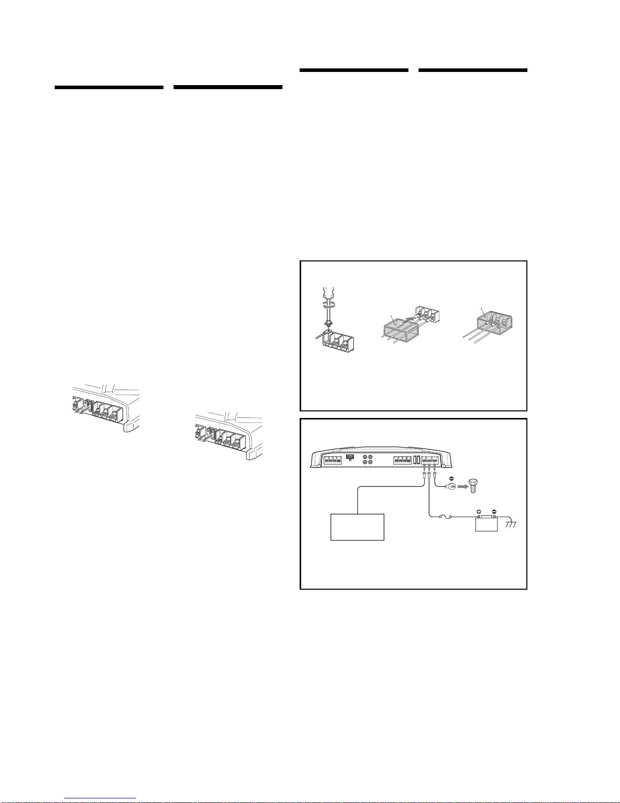
Power Connection Leads
Câbles d’alimentation
Car audio
Autoradio
Fuse (50 A)
Fusible (50 A)
+12 V car battery
Batterie de voiture +12 V
to a metal point
of the car
vers une partie
métallique de la
carrosserie
*
If you have the factory original or some other car audio without a remote out-put on the amplifier, connect
the remote input terminal (REMOTE) to the accessory power supply.
*
Si vous disposez du modèle d’origine ou d’un autre autoradio dont l’amplificateur ne comporte pas de sortie
de télécommande, raccordez la borne d’entrée de télécommande (REMOTE) à la prise d’alimentation
accessoires.
Notes on the po wer supply
•
Connect the +12 V power supply lead only after all
the other leads have been connected.
•
Be sure to connect the ground lead of the unit
securely to a metal point of the car. A loose
connection may cause a malfunction of the
amplifier.
•
Be sure to connect the remote control lead of the car
audio to the remote terminal.
• When using a car audio without a remote output on
the amplifier, connect the remote input terminal
(REMOTE) to the accessory power supply.
•
Use the power supply lead with a fuse attached
(50 A).
•
Place the fuse in the power supply lead as close as
possible to the car battery.
•
Make sure that the leads to be connected to the +12
V and GND terminals of this unit are at least 10Gauge (AWG-10) or have a sectional area of more
than 5 mm
2 (7
/32 in.2).
Remarques sur l’alimentation électrique
•
Raccordez le câble d’alimentation +12 V uniquement
après avoir réalisé toutes les autres connexions.
•
Raccordez correctement le fil de masse à une partie
métallique de la voiture. Une connexion lâche peut
provoquer un dysfonctionnement de l’amplificateur.
•
Veillez à raccorder le fil de télécommande de
l’autoradio à la borne de télécommande.
•
Si vous utilisez un autoradio dont l’amplificateur ne
comporte pas de sortie de télécommande, raccordez
la borne d’entrée de la télécommande (REMOTE) à la
prise d’alimentation accessoires.
•
Utilisez un câble d’alimentation muni d’un fusible
(50 A).
•
Fixez le câble d’alimentation le plus près possible de
la batterie de voiture.
•
Assurez-vous que les câbles à raccorder aux bornes
+12V et GND de cet appareil sont d’un calibre d’au
moins 10 (AWG-10) ou d’une section supérieure à
5mm
2 (7
/32 po2).
Remote output
*
Sortie de
télécommande
*
(REM OUT)
R
E
M
+
12V GND
3
3
Make the terminal connections as illustrated below.
Effectuez les connexions des borned comme illustré ci-dessous.
Pass the leads through the cap, connect
the leads, then cover the terminals with
the cap.
Note
When you tighten the screw, be careful not to
apply too much torque
*
as doing so may damage
the screw.
*
The torque value should be less than 1 N•m.
Faites passer les fils par le chache,
raccordez les fils, puis recouverz les bornes
avec le cache.
Remarque
Lorsque vous vissez la vis, faites attention à ne
pas appliquer une trop grande force
*
, car cela
pourrait endommager la vis.
*
Lecouple de torsion doit être inférieur à 1 N•m.
5
XM-460GTX
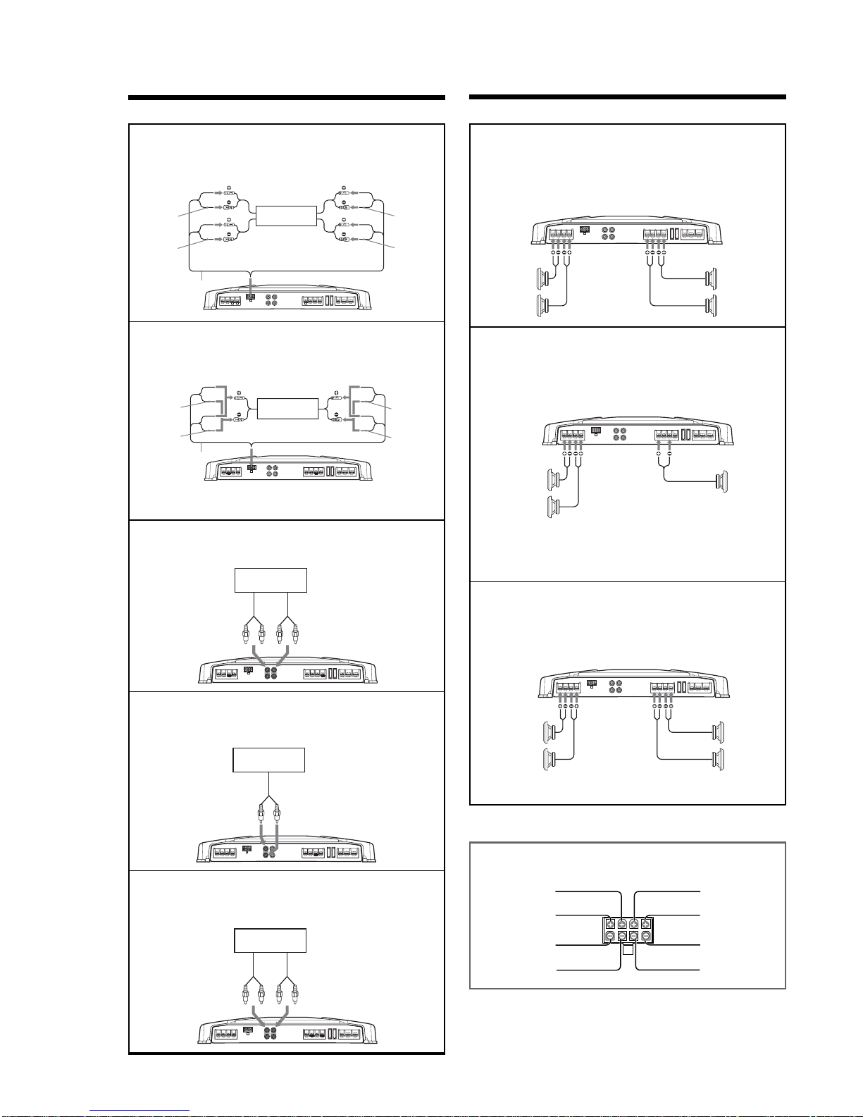
Input Connections/Connexions d’entrée
High Level Input Connection
(with Speaker Connection 1, 2 or 3)
Connexion à l’entrée de haut niveau
(avec connexion de
haut-parleur 1, 2 ou 3)
AA
AA
A
Speaker Connections/Raccordement de haut-parleurs
Car audio
Autoradio
Front left speaker output
Sortie de haut-parleur avant
gauche
Rear left speaker output
Sortie de haut-parleur
arrière gauche
Rear right speaker output
Sortie de haut-parleur arrière droit
Front right speaker output
Sortie de haut-parleur avant droit
High Level Input Connection
(with Speaker Connection 2 or 3)
Connexion à l’entrée de haut niveau
(avec connexion de
haut-parleur 2 ou 3)
BB
BB
B
Remarque
Assurez-vous que la sortie du haut-parleur droit de
l’autoradio est raccordée au connecteur portant
l’indication “REAR” sur l’appareil.
Note
Make sure that the right speaker output from the
car audio is connected to the connector marked
“REAR” on the unit.
Line Input Connection
(with Speaker Connection 1, 2 or 3)
Connexion d’entrée de ligne
(avec connexion de
haut-parleur 1, 2 ou 3)
CC
CC
C
Car audio
Autoradio
LINE OUT
Front
Avant
Rear
Arrière
Line Input Connection
(with Speaker Connection 1, 2 or 3)
Connexion d’entrée de ligne
(avec connexion de
haut-parleur 1, 2 ou 3)
DD
DD
D
*
High Level Input Connector
*
Connecteur d’entrée à haut niveau
Gray
Gris
White
Blanc
Striped/White
Rayé/Blanc
LR LR
FRONT R EAR
Striped/Gray
Rayé/Gris
Green
Vert
Purple
Mauve
Striped/Purple
Rayé/Mauve
Striped/Green
Rayé/Vert
Gray
Gris
White
Blanc
Striped
Rayé
Striped
Rayé
Green
Vert
Purple
Mauve
Striped
Rayé
Striped
Rayé
2
Car audio
Autoradio
Right speaker output
Sortie de haut-parleur droit
Left speaker output
Sortie de haut-parleur gauche
Gray
Gris
White
Blanc
Striped
Rayé
Striped
Rayé
Green
Vert
Purple
Mauve
Striped
Rayé
Striped
Rayé
2
Car audio
Autoradio
LINE OUT
Left channel
Canal gauche
Right channel
Canal droit
Line Input Connection
(with Speaker Connection 2 or 3)
Connexion d’entrée de ligne
(avec connexion de
haut-parleur 2 ou 3)
EE
EE
E
4-Speaker System
(with Input Connection A, C or D)
Système à 4 haut-parleurs
(avec connexion d’entrée
A, C ou D)
11
11
1
Front speakers
(min. 2Ω)
Haut-parleurs avant
(min. 2Ω)
Left
Gauche
Right
Droit
Right
Droit
Left
Gauche
Pour plus de détails sur les réglages des
commutateurs et commandes, reportez-vous à
“Emplacement et fonction des commandes.”
For details on the settings of switches and
controls, refer to “Location and Function of
Controls.”
Car audio
Autoradio
LINE
OUT
SUB
WOOFER
OUT
Rear speakers
(min. 2Ω)
Haut-parleurs arrière
(min. 2Ω)
3-Speaker System
(with Input Connection A, B, C, D or E)
Système à 3 haut-parleurs
(avec connexion d’entrée A, B,
C, D ou E)
22
22
2
Left
Gauche
Right
Droit
Full range speakers
(min. 2Ω)
Haut-parleurs pleine
gamme (min. 2Ω)
Subwoofer
(min. 4Ω)
Subwoofer
(min. 4Ω)
Notes
•In this system, the volume of the subwoofer will
be controlled by the car audio fader control.
•In this system, the output signals to the
subwoofer are a combination of both the REAR
L and R INPUT jacks or the REAR high level input
connector signals.
Remarques
• Dans ce système, le volume du subwoofer est
contrôlé par le fader de l’autoradio.
• Sur cet appareil, les signaux tr ansmis vers le
subwoofer sont constitués des signaux des prises
REAR L et R INPUT.
Pour plus de détails sur les réglages des
commutateurs et commandes, reportez-vous à
“Emplacement et fonction des commandes.”
For details on the settings of switches and
controls, refer to “Location and Function of
Controls.”
2-Way System
(with Input Connection A, B, C, D or E)
Système à 2 voies
(avec connexion d’entrée A, B, C,
D ou E)
33
33
3
Full range speakers
(min. 2Ω)
Haut-parleurs pleine
gamme (min. 2Ω)
Right
Droit
Left
Gauche
Right
Droit
Left
Gauche
Subwoofers
(min. 2Ω)
Subwoofers
(min. 2Ω)
Pour plus de détails sur les réglages des
commutateurs et commandes, reportez-vous à
“Emplacement et fonction des commandes.”
For details on the settings of switches and
controls, refer to “Location and Function of
Controls.”
Remarque
Dans ce système, le volume des subwoofers est
contrôlé par le fader de l’autoradio.
Note
In this system, the volume of the subwoofers will
be controlled by the car audio fader control.
Note
Do not use when only
L and R is connected.
*
*
Remarque
Ne pas utiliser lorsque
L et R uniquement
sont raccordés.
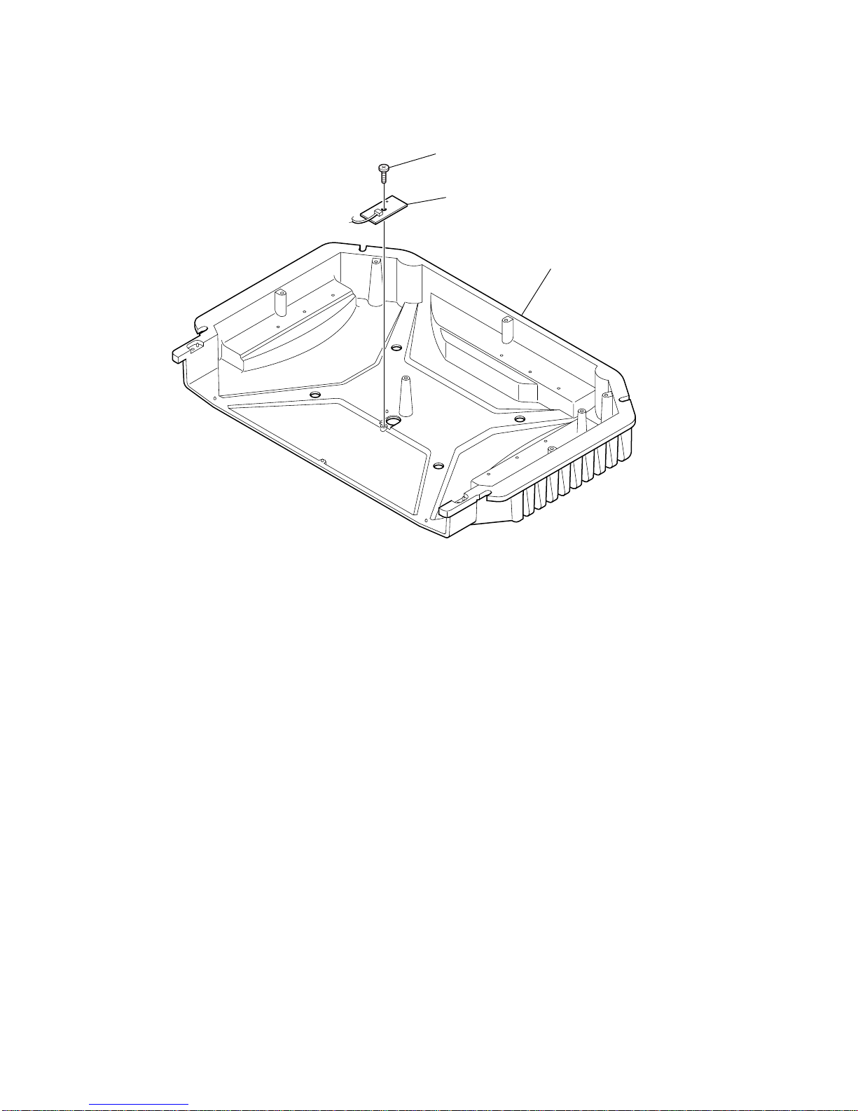
6
XM-460GTX
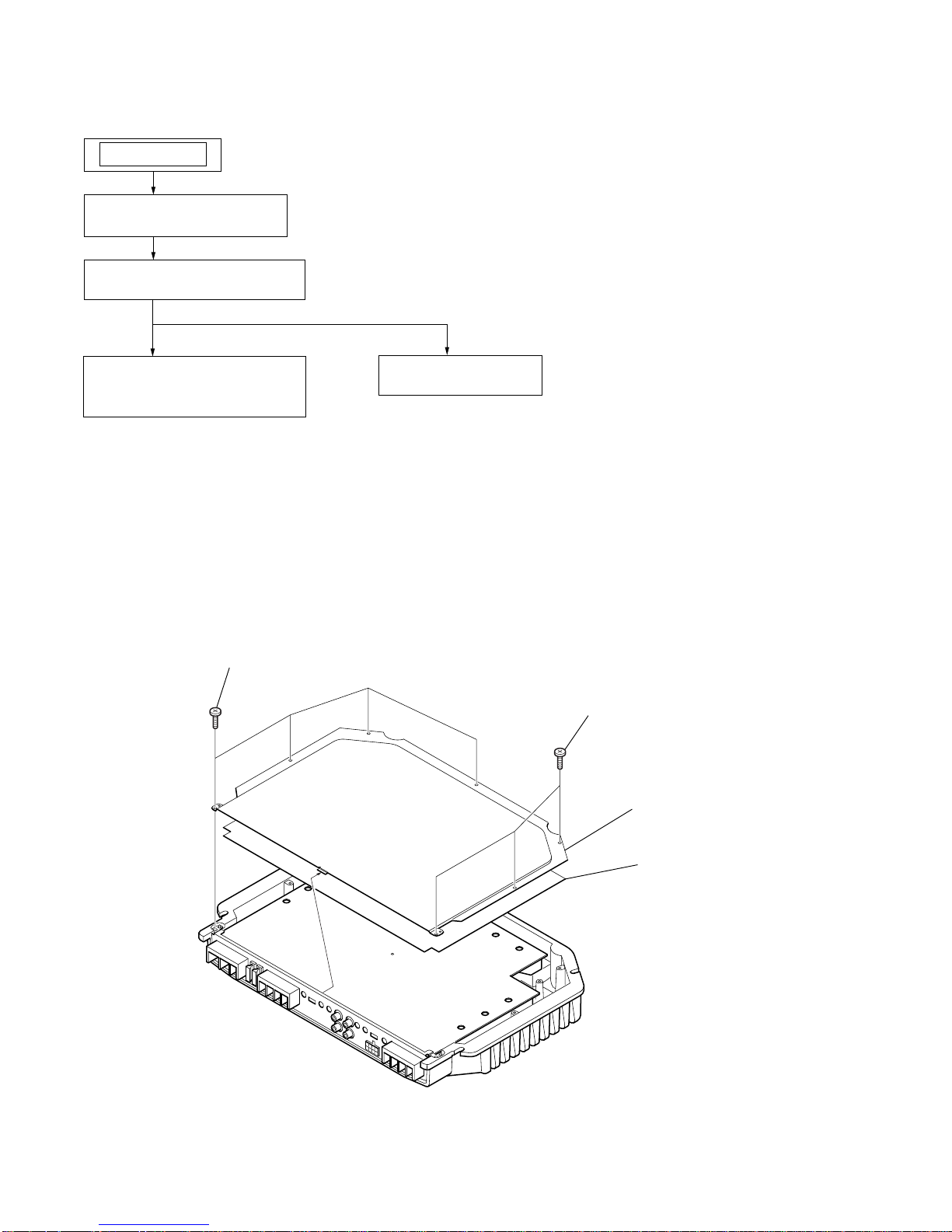
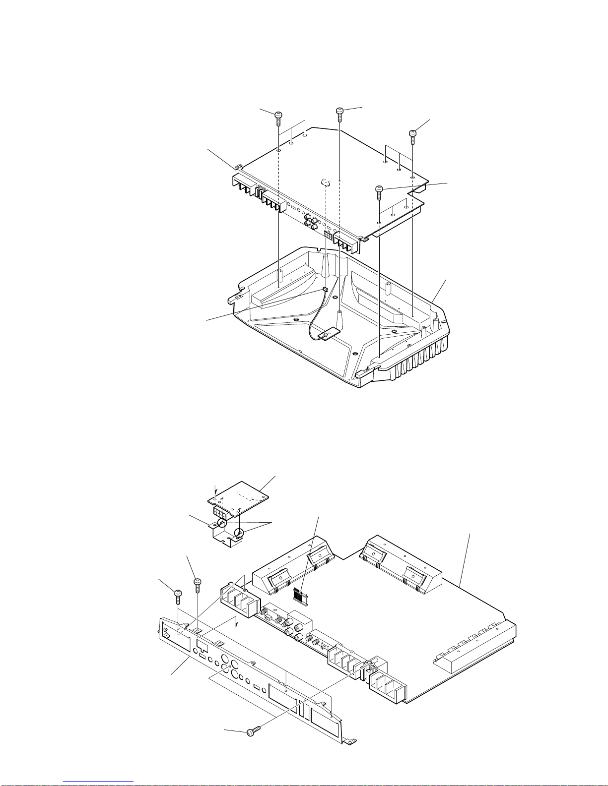
SECTION 2
DISASSEMBLY
Note : Follow the disassembly procedure in the numerical order given.
2-1. BOTTOM PLATE
Note : This set can be disassemble according to the following sequence.
2-1. BOTTOM PLATE
(Page 6)
2-2. MAIN BOARD SECTION
(Page 7)
2-4. LED BOARD
(Page 8)
SET
2-3. MAIN BOARD,
HI-LEVEL BOARD
(Page 7)
1
BTP 3x6
3
bottom plate
4
insulating shee
t
2
BTP 3x6
7
XM-460GTX
2-3. MAIN BOARD, HI-LEVEL BOARD
2-2. MAIN BOARD SECTION
1
P 3x8
heat sink (main
)
2
P 3x8
3
P 3x8
4
P 3x8
6
CN850
5
MAIN board section
4
P 3x8
1
P 3x8
2
P 3x8
7
panel (front)
5
HI-LEVEL board
3
CNP101
8
MAIN board
claws
6
bracket (HI-LEVEL)
A
A
8
XM-460GTX
2-4. LED BOARD
1
BTP 3x6
2
LED board
heat sink (main)
 Loading...