

1300-3566 Rev 6
Sony Mobile Communications AB – Company Internal
Working Instructions
- mechanical -
Xperia
TM
Z5
E6603, E6653
Xperia
TM
Z5 Dual
E6633, E6683

1300-3566 Rev 6
Sony Mobile Communications AB – Company Internal
2(64)
Working Instruction Repair Instruction Mechanical/E6603, E6653, E6633, E6683/
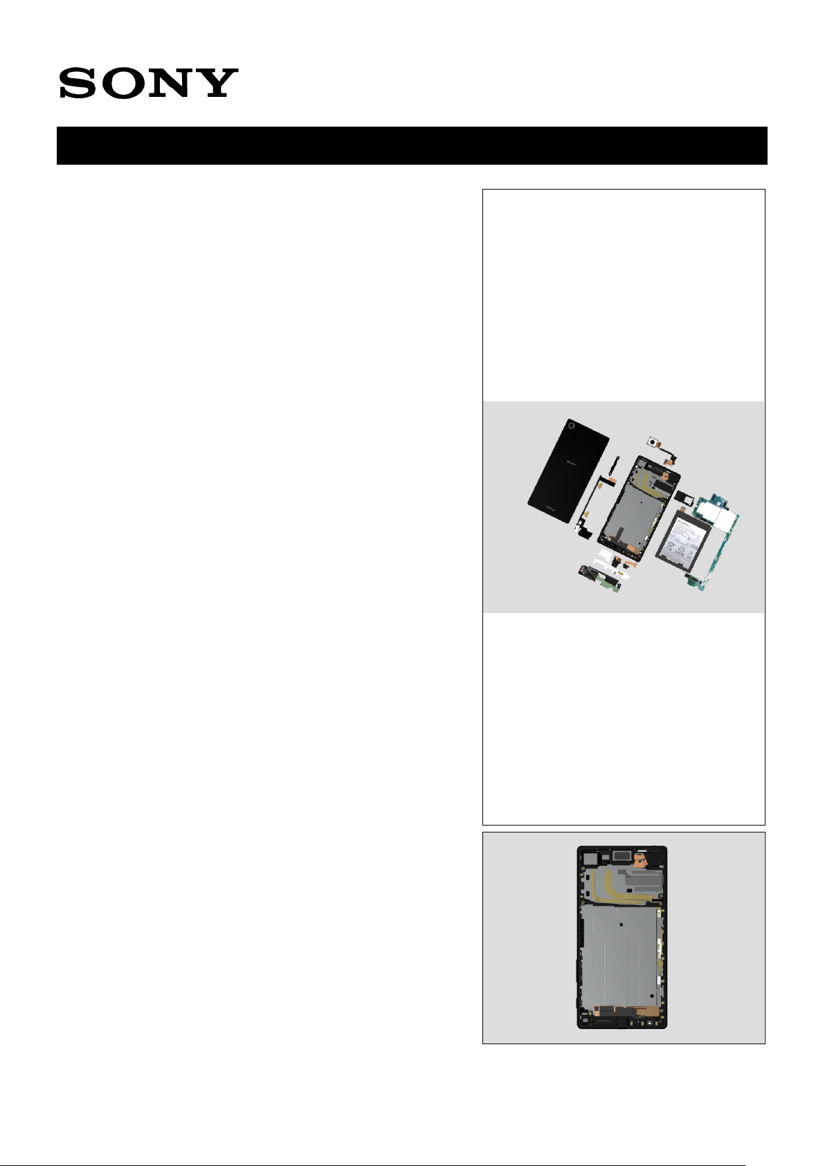
CONTENTS
1 Exterior Views ................................................................................. 5
1.1 E6603/E6653/E6633/E6683 ................................................................... 5
2 Tools ................................................................................................ 6
3 Disassembly.................................................................................... 9
3.1 Tray Combo .......................................................................................... 9
3.2 Panel Rear .......................................................................................... 10
3.3 Holder PBA ......................................................................................... 12
3.4 Antenna Cell Sub ............................................................................... 12
3.5 Camera Main ....................................................................................... 13
3.6 Camera Sub ........................................................................................ 13
3.7 Man PBA ............................................................................................. 14
3.8 FPC 1st Mic ......................................................................................... 16
3.9 FPC USB ............................................................................................. 16
3.10 Shield FPC LCD .................................................................................. 16
3.11 Adhesive Battery ................................................................................ 17
3.12 Battery Embedded ............................................................................. 17
3.13 FPC Key .............................................................................................. 17
3.14 Antenna Cell Main .............................................................................. 18
4 Replacement ................................................................................. 19
4.1 Antenna Cell Main & Sheet Holder Speaker & Cushion Battery
Bottom ................................................................................................ 19
4.2 Antenna Cell Sub & Gasket Conductive Sub Camera ..................... 19
4.3 Antenna WiFi Sub .............................................................................. 19
4.4 Battery Embedded & Adhesive Battery ............................................ 20
4.5 Cap ...................................................................................................... 20
4.6 Cushion Main Camera ........................................................................ 21
4.7 Antenna NFC ...................................................................................... 21
4.8 Camera Main & Holder Main Camera & Cushion BtoB A ................ 21
4.9 Camera Sub & Holder Sub Camera & Cushion BtoB B ................... 21
4.10 FPC 1st Mic & Adhesive FPC 1st Mic ............................................... 22
4.11 FPC Key & Adhesive FPC Speaker & Plate Speaker & Sheet
Conductive FPC Relay ....................................................................... 22
4.12 FPC Top & Adhesive Audio Jack & Adhesive Holder 2nd Mic &
Cushion Shade Audio Jack & Holder 2nd Mic & Sheet Holder 2nd
Mic & Sheet Shade Audio Jack 2 ...................................................... 23
4.13 FPC USB & Cushion BtoB C & Sheet Spacer USB .......................... 27
4.14 Front Assy .......................................................................................... 27
4.15 Gasket Conductive Relay-U ............................................................... 27

1300-3566 Rev 6
Sony Mobile Communications AB – Company Internal
3(64)
Working Instruction Repair Instruction Mechanical/E6603, E6653, E6633, E6683/
4.16 Gasket Speaker Bottom ..................................................................... 28
4.17 Holder PBA ......................................................................................... 29
4.18 Holder Vib ........................................................................................... 29
4.19 Label MoP ........................................................................................... 29
4.20 Light Guide 3LED / Light Guide 3LED Transparent ......................... 31
4.21 Loudspeaker & Adhesive Ear Speaker & Cushion ACO .................. 31
4.22 Panel Rear .......................................................................................... 32
4.23 Adhesive Panel Rear ................................................................ .......... 32
4.24 RF Coax Cable .................................................................................... 32
4.25 Sheet Conductive LCD FPC A ........................................................... 33
4.26 Sheet Guide MoP ................................................................................ 33
4.27 Sheet Slider MoP ................................................................................ 33
4.28 Sheet WR Test .................................................................................... 35
4.29 Sheet ZIF LCD. .................................................................................... 35
4.30 Shield Camera .................................................................................... 35
4.31 Shield FPC LCD & Sheet BtoB Touch ............................................... 35
4.32 Spacer Panel Right............................................................................. 36
4.33 Thermal Gap Filler .............................................................................. 37
4.34 Top Speaker & Adhesive Speaker Bottom ....................................... 38
4.35 Tray Combo ........................................................................................ 39
4.36 Water indicator ................................................................................... 39
4.37 Main PBA & Cushion TGF Lower/Upper/D & Sheet Protection MoP
Label – Board Swap Replacement .................................................... 40
4.38 Board Swap – Change Label ............................................................. 40
4.39 Board Swap – Customize of Software .............................................. 41
5 Reassembly................................................................................... 42
5.1 Front Assy .......................................................................................... 42
5.2 Sheet Slider MoP ................................................................................ 43
5.3 Gasket Speaker Bottom ..................................................................... 44
5.4 Sheet Conductive LCD FPC A ........................................................... 44
5.5 Sheet BtoB Touch & Shield FPC LCD ............................................... 45
5.6 Loudspeaker & Cushion ACO ........................................................... 45
5.7 Shield Camera .................................................................................... 46
5.8 Sheet Spacer USB & FPC USB .......................................................... 46
5.9 FPC 1st Mic ......................................................................................... 47
5.10 Sheet Protection MoP Label .............................................................. 47
5.11 Sheet TGF Upper & Lower / Sheet TGF D ......................................... 48
5.12 Thermal Gap Filler .............................................................................. 48
5.13 Main PBA ............................................................................................ 54
5.14 Holder PBA ......................................................................................... 54

1300-3566 Rev 6
Sony Mobile Communications AB – Company Internal
4(64)
Working Instruction Repair Instruction Mechanical/E6603, E6653, E6633, E6683/
5.15 Holder Sub Camera & Camera Sub ................................................... 55
5.16 Gasket Conductive Sub Camera & Antenna Cell Sub ..................... 55
5.17 FPC Key & Sheet Conductive FPC Relay ......................................... 56
5.18 Sheet Holder Speaker & Adhesive Speaker Bottom & Top Speaker
57
5.19 Adhesive FPC Speaker ...................................................................... 58
5.20 Antenna Cell Main .............................................................................. 58
5.21 Holder Vib ........................................................................................... 58
5.22 FPC Key 2 & Plate Speaker ................................................................ 58
5.23 Camera Main & Holder Main Camera ................................................ 59
5.24 RF Coax Cable .................................................................................... 59
5.25 Cushion Battery ................................................................................. 60
5.26 Adhesive Battery & Battery Embedded ............................................ 60
5.27 Cushion BtoB A & B & C ................................................................... 61
5.28 Antenna NFC ...................................................................................... 61
5.29 Adhesive Panel Rear ................................................................ .......... 62
5.30 Panel Rear .......................................................................................... 62
6 Revision History ........................................................................... 64
For general information about mechanical repair related issues, refer to
1220-1333: Generic Repair Manual - mechanical
Always firstly disconnect the Battery FPC BtB connector to cut off power supply when the Panel
Rear is disassembled.
If there are no special indications of ‘E6633’ or ‘E6683’, E6633 and E6683 share the same repair
method as common sections
1300-3566 Rev 6
Sony Mobile Communications AB – Company Internal
5(64)
Working Instruction Repair Instruction Mechanical/E6603, E6653, E6633, E6683/
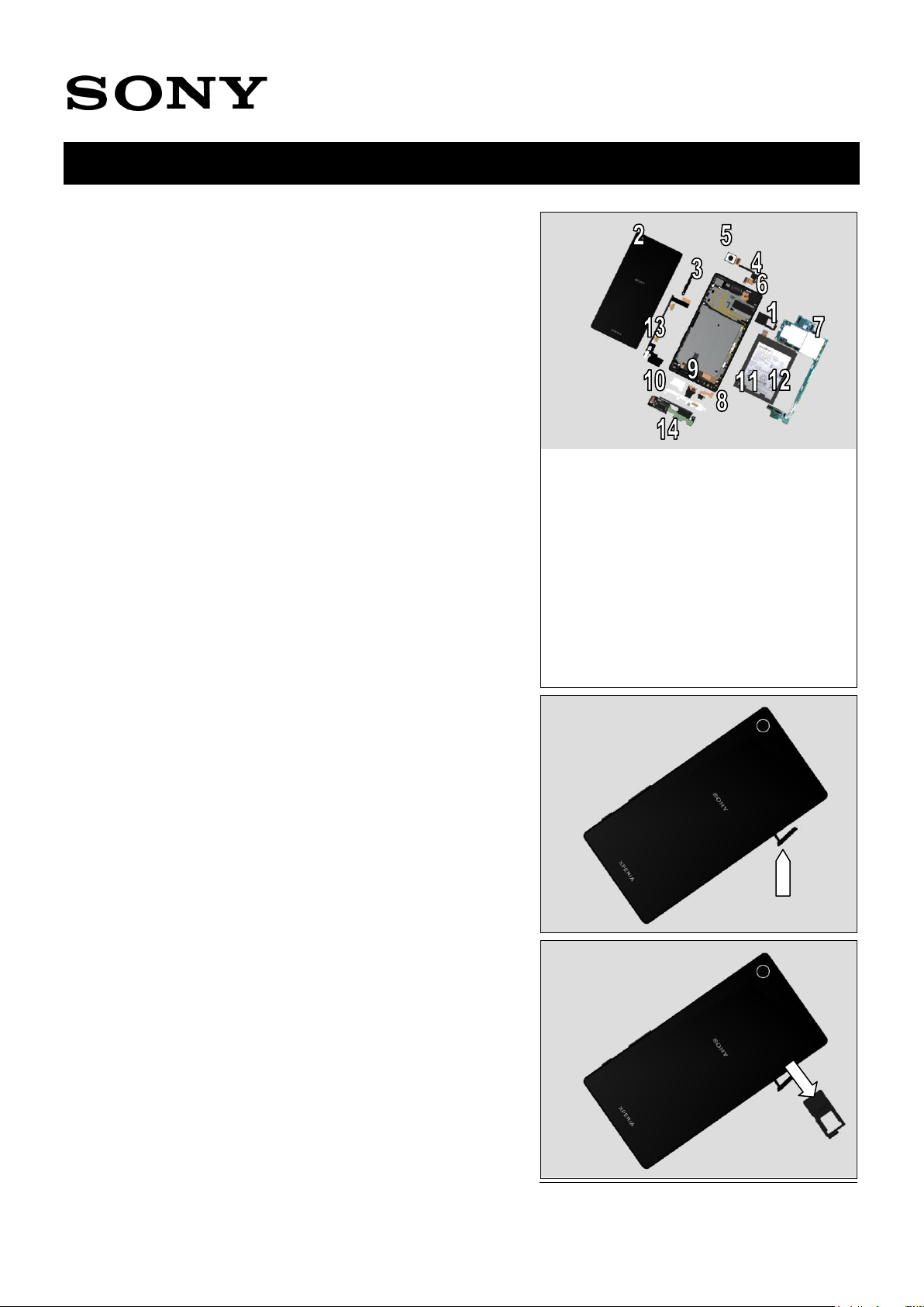
1 Exterior Views
1.1 E6603/E6653/E6633/E6683
1300-3566 Rev 6
Sony Mobile Communications AB – Company Internal
6(64)
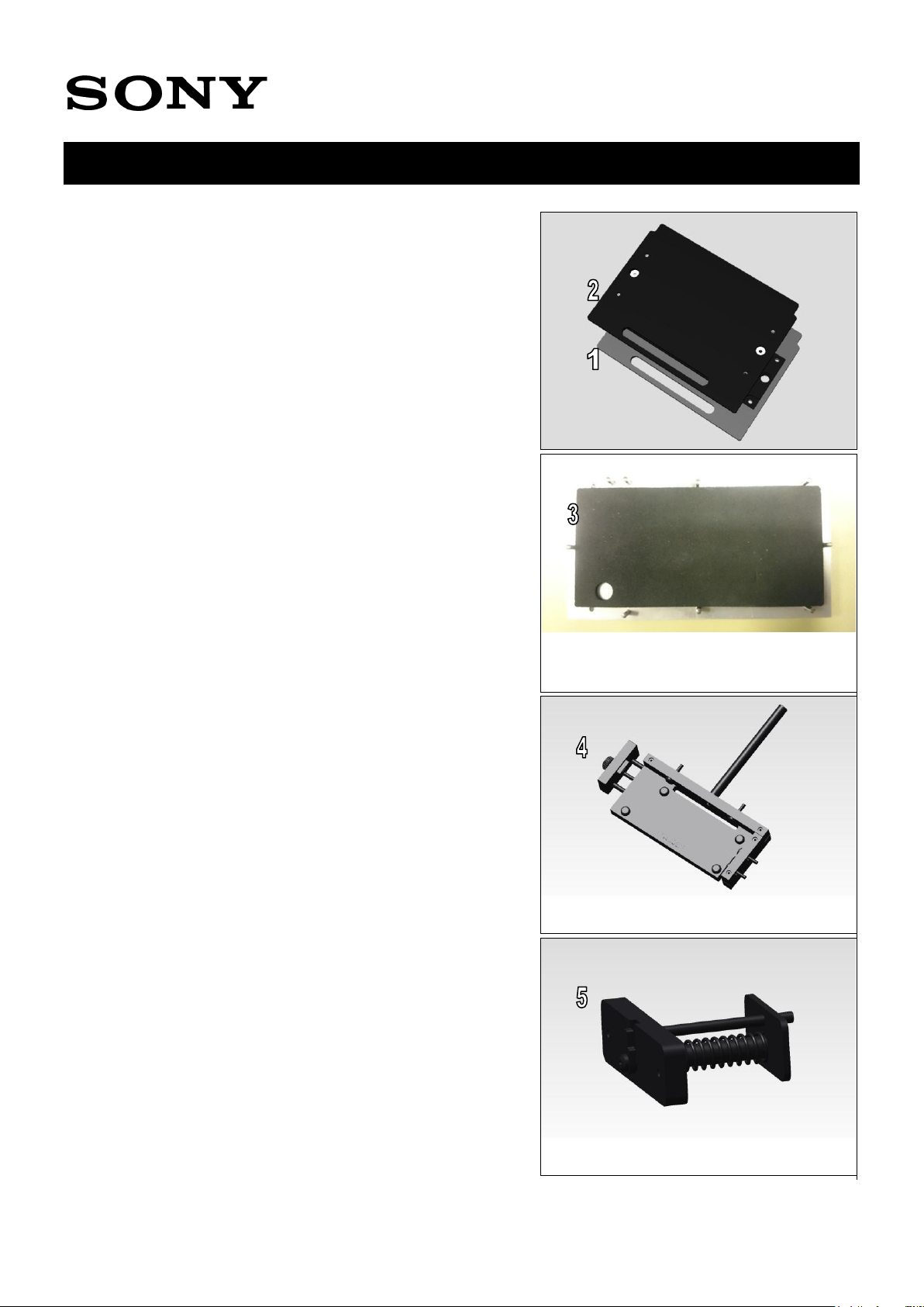
SPECIAL TOOLS
1. Bottom Press Inlay 1297-5969
2. Rear Panel Press Top Inlay 1297-5970
3. Rear Panel Adhesive Alignment Fixture 1297-5971
4.WRT Fixture 1297-5983
5. FPC Jack Module Press 1297-5984
Working Instruction Repair Instruction Mechanical/E6603, E6653, E6633, E6683/
2 Tools
1300-3566 Rev 6
Sony Mobile Communications AB – Company Internal
7(64)
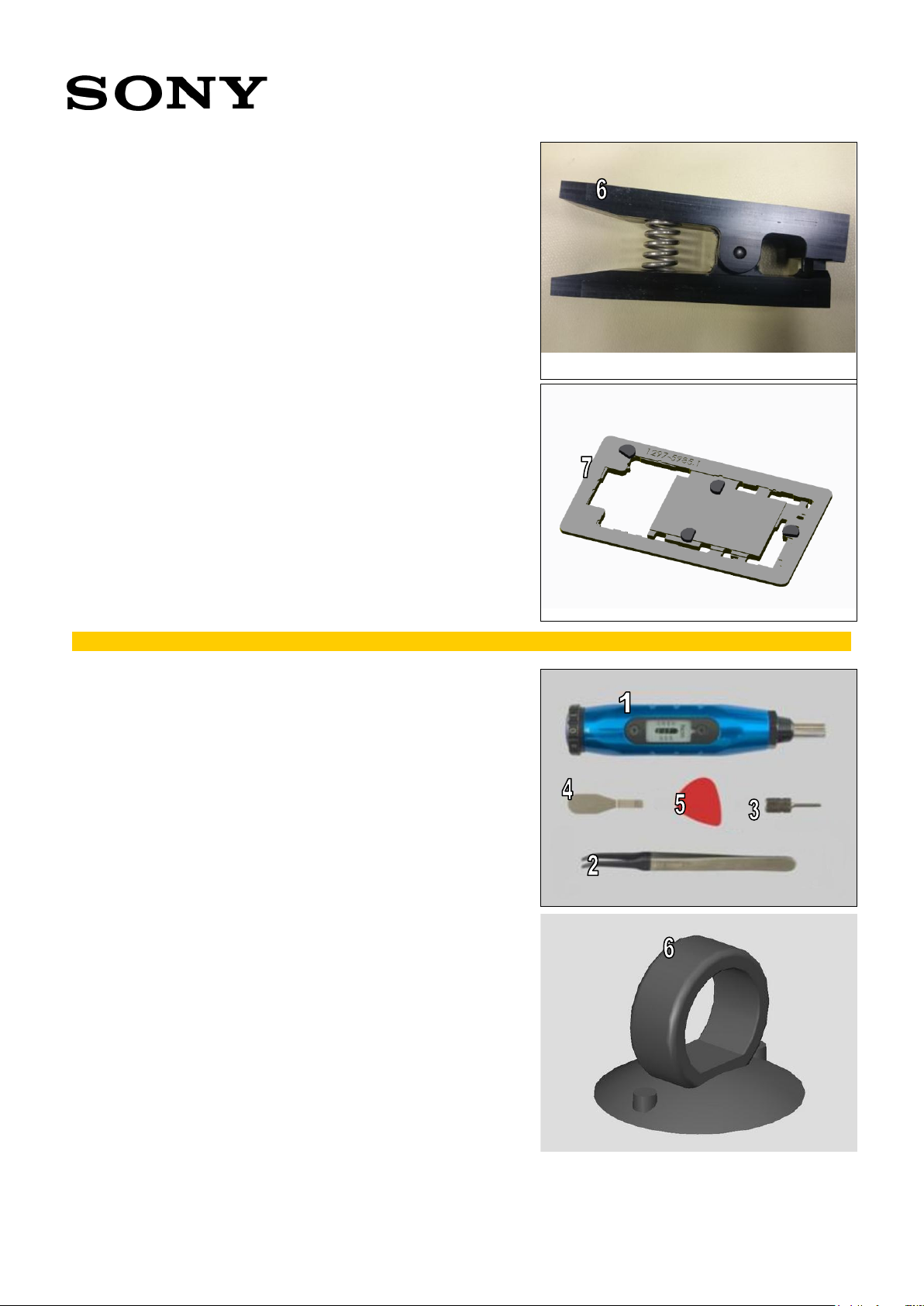
6. Gasket WR SPK Press 1298-1228
7. Soldering Fixture 1297-5985
For part no’s on the tools above, refer to the ‘Tools Catalogue/Matrix’!
STANDARD TOOLS
1. Torque Screwdriver
2. Flex Film Assembly Tool
3. Bits JCIS No.0
4. Front Opening Tool
5. Guitar Pick
6. Suction cup
Working Instruction Repair Instruction Mechanical/E6603, E6653, E6633, E6683/
1300-3566 Rev 6
Sony Mobile Communications AB – Company Internal
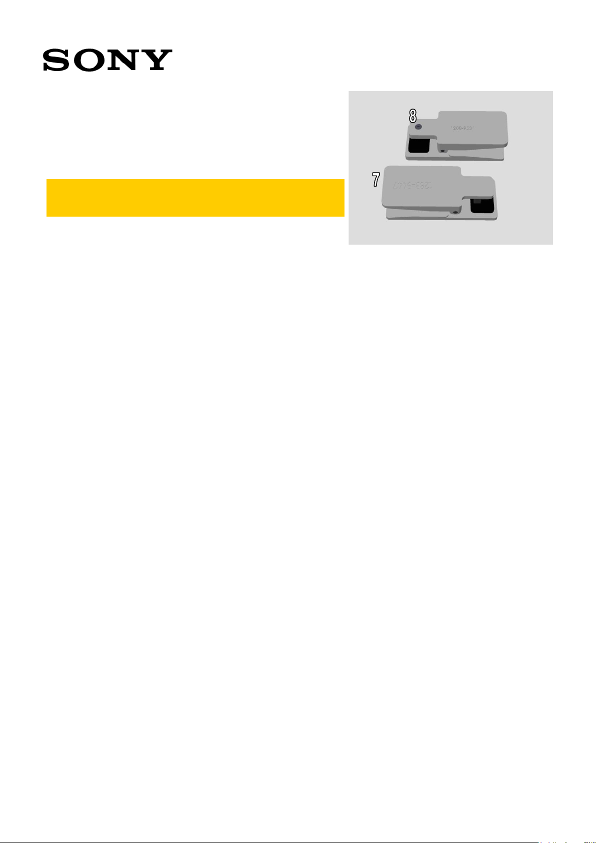
8(64)
7. Earspeaker/Loudspeaker Top Press Tool (1283-9447) for
upper speaker
8. Press Tool Ear Speaker (1288-9531) for lower speaker
Note! Due to limitation of order system, names of above
tools come from the naming in the past model. Please
be careful.
Working Instruction Repair Instruction Mechanical/E6603, E6653, E6633, E6683/
1300-3566 Rev 6
Sony Mobile Communications AB – Company Internal
9(64)
The disassembly is done in the following order:
1. Tray Combo
2. Panel Rear
3. Holder PBA
4. Antenna Cell Sub
5. Camera Main
6. Camera Sub
7. Main PBA
8. FPC 1st Mic
9. FPC USB
10. Shield FPC LCD
11. Adhesive Battery
12. Battery Embedded
13. FPC Key
14. Antenna Cell Main
3.1 Tray Combo
Open the Cap.
Remove the Tray Combo.
(For E6603, E6653)
Working Instruction Repair Instruction Mechanical/E6603, E6653, E6633, E6683/
3 Disassembly
1300-3566 Rev 6
Sony Mobile Communications AB – Company Internal
10(64)
(For E6633, E6683)
Close the Cap.
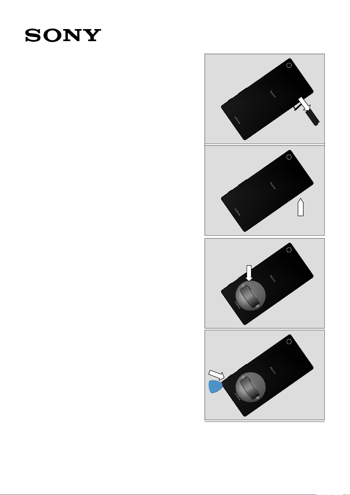
3.2 Panel Rear
Put the suction cup on the Panel Rear and pull up.
Insert the Guitar Pick.
Working Instruction Repair Instruction Mechanical/E6603, E6653, E6633, E6683/
1300-3566 Rev 6
Sony Mobile Communications AB – Company Internal
11(64)
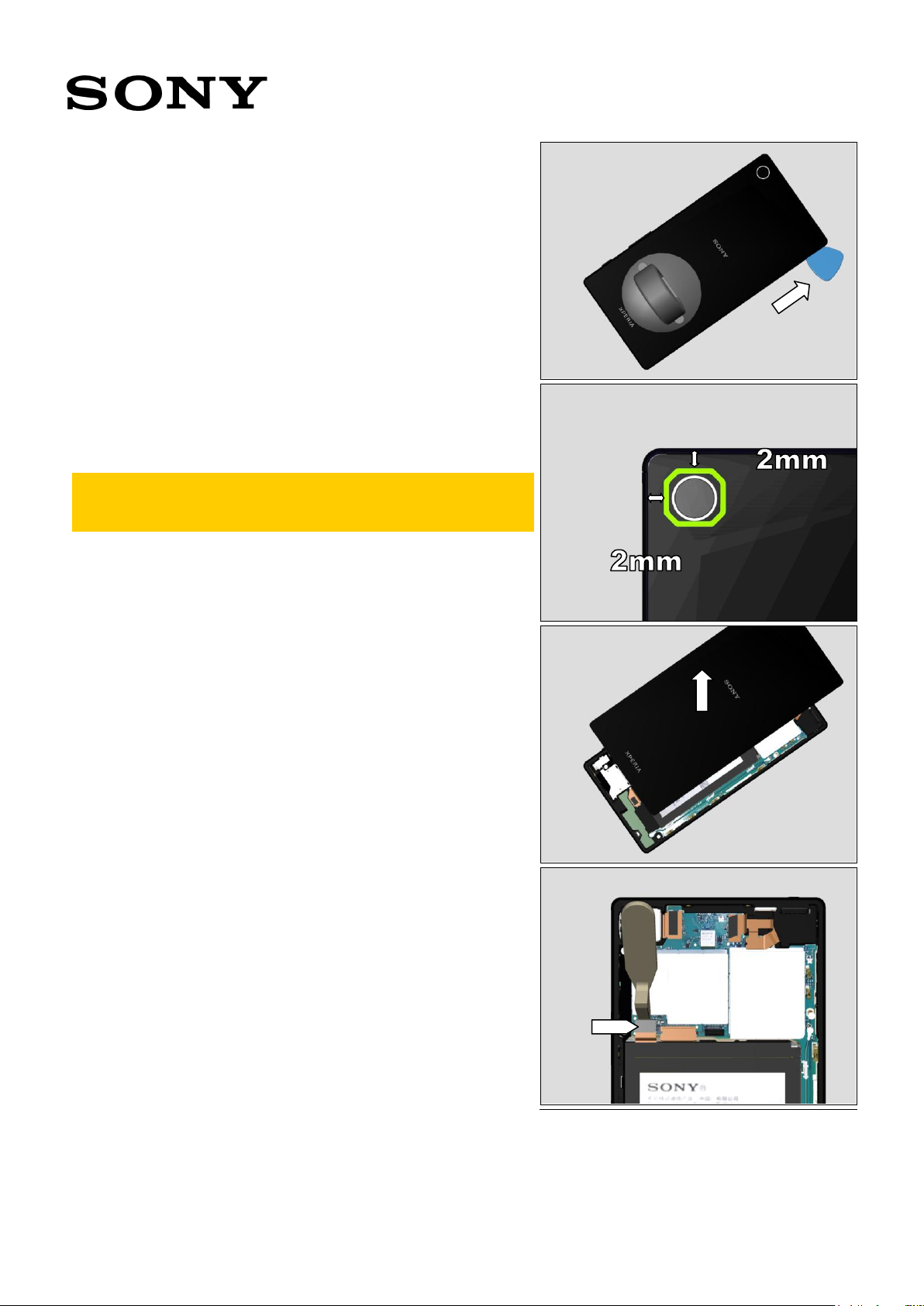
Gently slide the Guitar Pick along the rim.
Pay special attention at the upper side not to damage
the Cushion Main Camera. Do not insert the Guitar Pick
more than 2mm.
Remove the Panel Rear.
Disconnect the Battery Embedded connector right after
disassembling the Panel Rear.
Working Instruction Repair Instruction Mechanical/E6603, E6653, E6633, E6683/
1300-3566 Rev 6
Sony Mobile Communications AB – Company Internal
12(64)
3.3 Holder PBA
Remove the two screws on the Holder PBA.
Remove the Holder PBA.
3.4 Antenna Cell Sub
Disconnect the FPC Top connector.
Remove the screw on the Antenna Cell Sub.
Working Instruction Repair Instruction Mechanical/E6603, E6653, E6633, E6683/

1300-3566 Rev 6
Sony Mobile Communications AB – Company Internal
13(64)
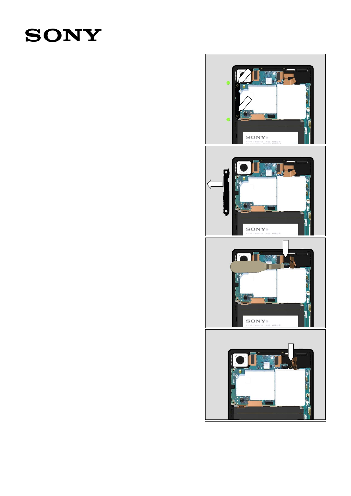
Remove the Antenna Cell Sub
3.5 Camera Main
Disconnect the Camera Main Connector.
Remove the Camera Main.
3.6 Camera Sub
Disconnect the Camera Sub Connector.
Working Instruction Repair Instruction Mechanical/E6603, E6653, E6633, E6683/
1300-3566 Rev 6
Sony Mobile Communications AB – Company Internal
14(64)
Remove the Camera Sub.
3.7 Man PBA
Remove the remaining screws on the Main PBA.
E6633, E6683 have one less screw on the PBA.
Disconnect the FPC Key connector.
Working Instruction Repair Instruction Mechanical/E6603, E6653, E6633, E6683/
1300-3566 Rev 6
Sony Mobile Communications AB – Company Internal
15(64)
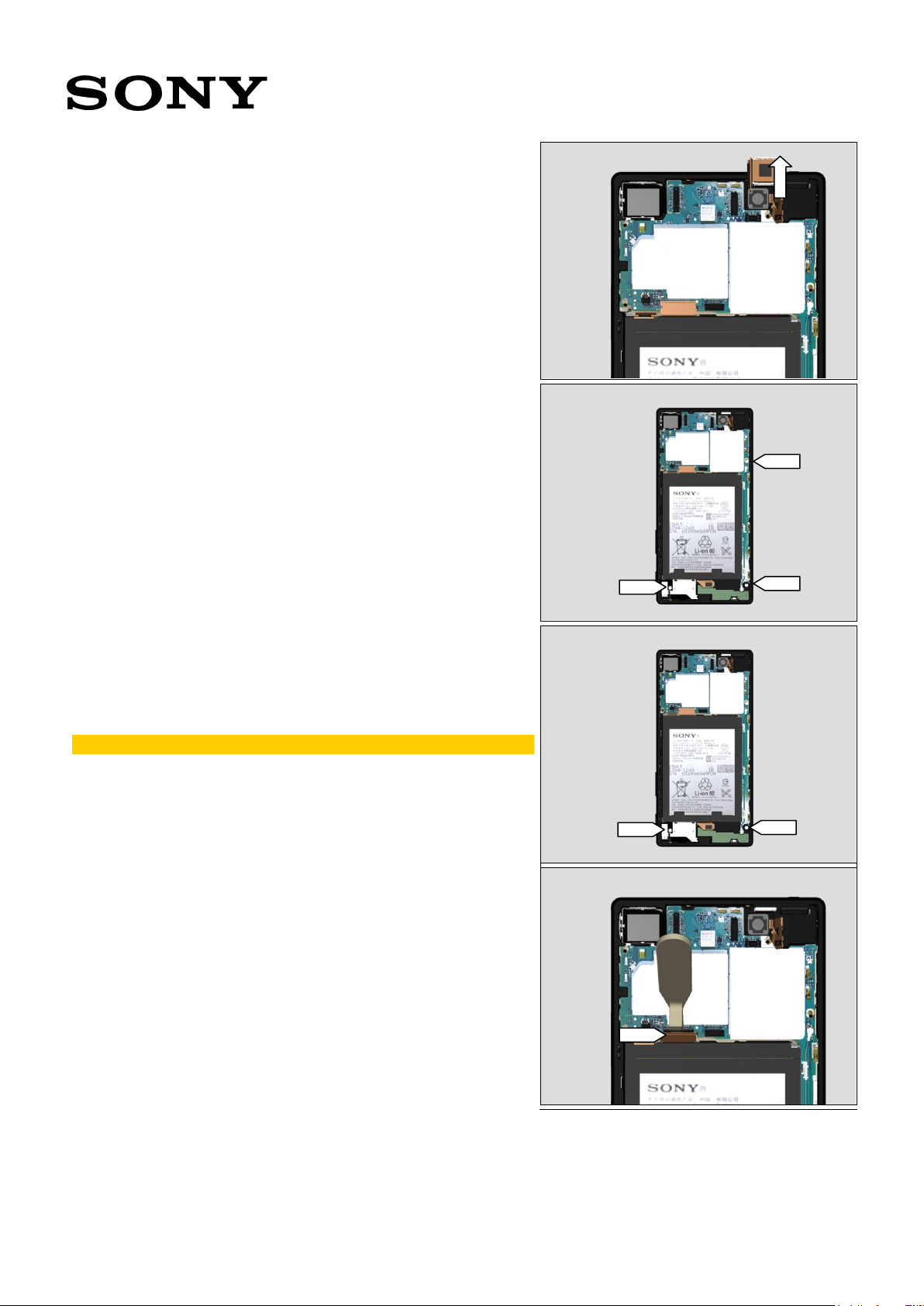
Gently open the Antenna Cell Main with the Top FPC up to
the right angle.
Note! Do not break the FPC Key!
Disconnect three connectors at the bottom.
Pull up the left side of the Main PBA.
Remove the Main PBA.
Working Instruction Repair Instruction Mechanical/E6603, E6653, E6633, E6683/
1300-3566 Rev 6
Sony Mobile Communications AB – Company Internal
16(64)
3.8 FPC 1st Mic
Remove the FPC 1st Mic.
3.9 FPC USB
Slide upwards the FPC USB.
Remove the FPC USB.
3.10 Shield FPC LCD
Remove the Shield FPC LCD.
Working Instruction Repair Instruction Mechanical/E6603, E6653, E6633, E6683/
1300-3566 Rev 6
Sony Mobile Communications AB – Company Internal
17(64)
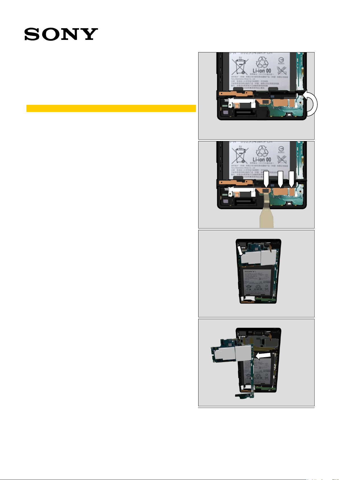
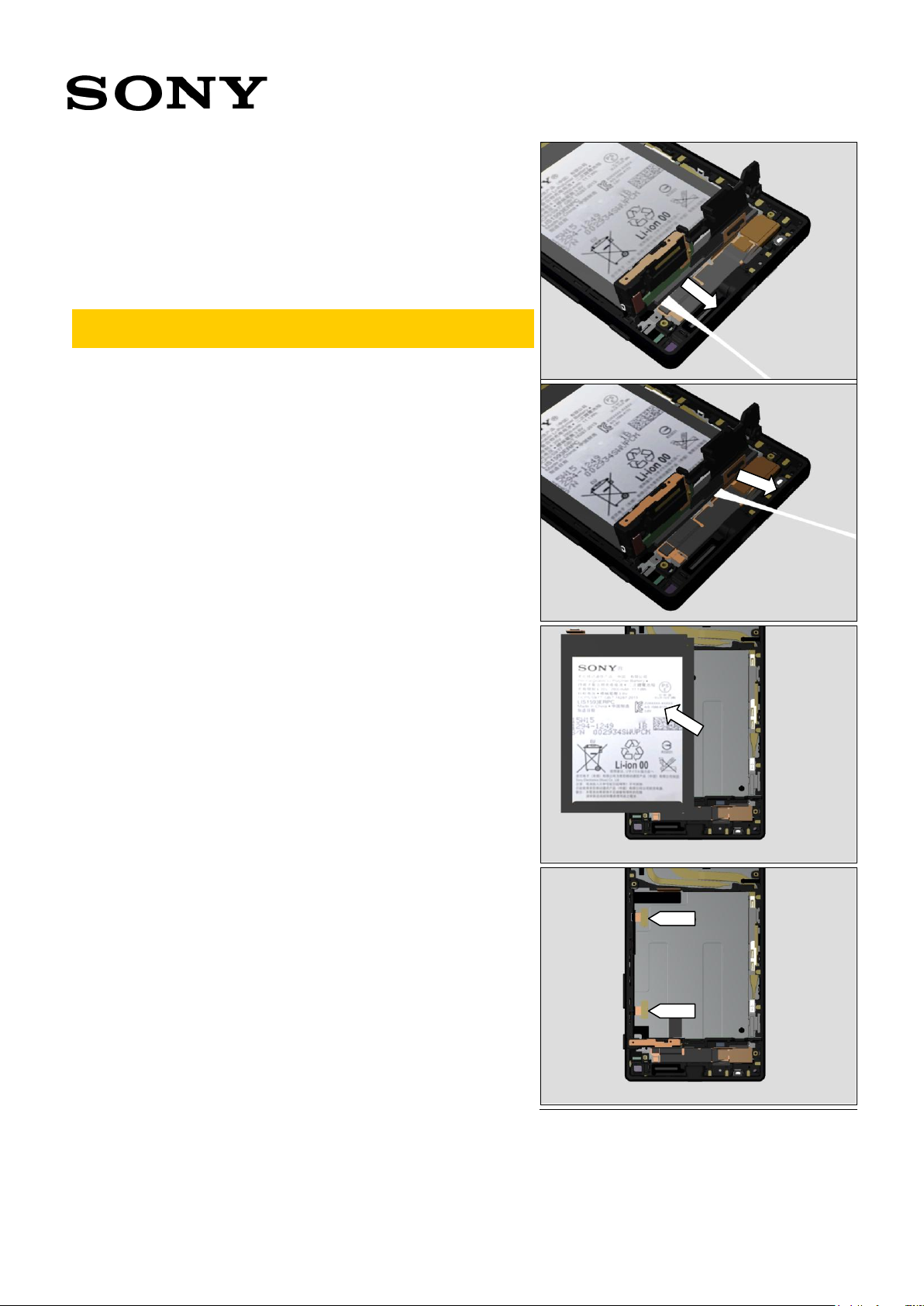
3.11 Adhesive Battery
Pinch the Adhesive Battery tab.
Slowly pull out the Adhesive Battery to planar direction.
Do not twist the tab. Do not make the adhesive touch
any of other components.
Remaining tab as well.
3.12 Battery Embedded
Remove the Battery Embedded.
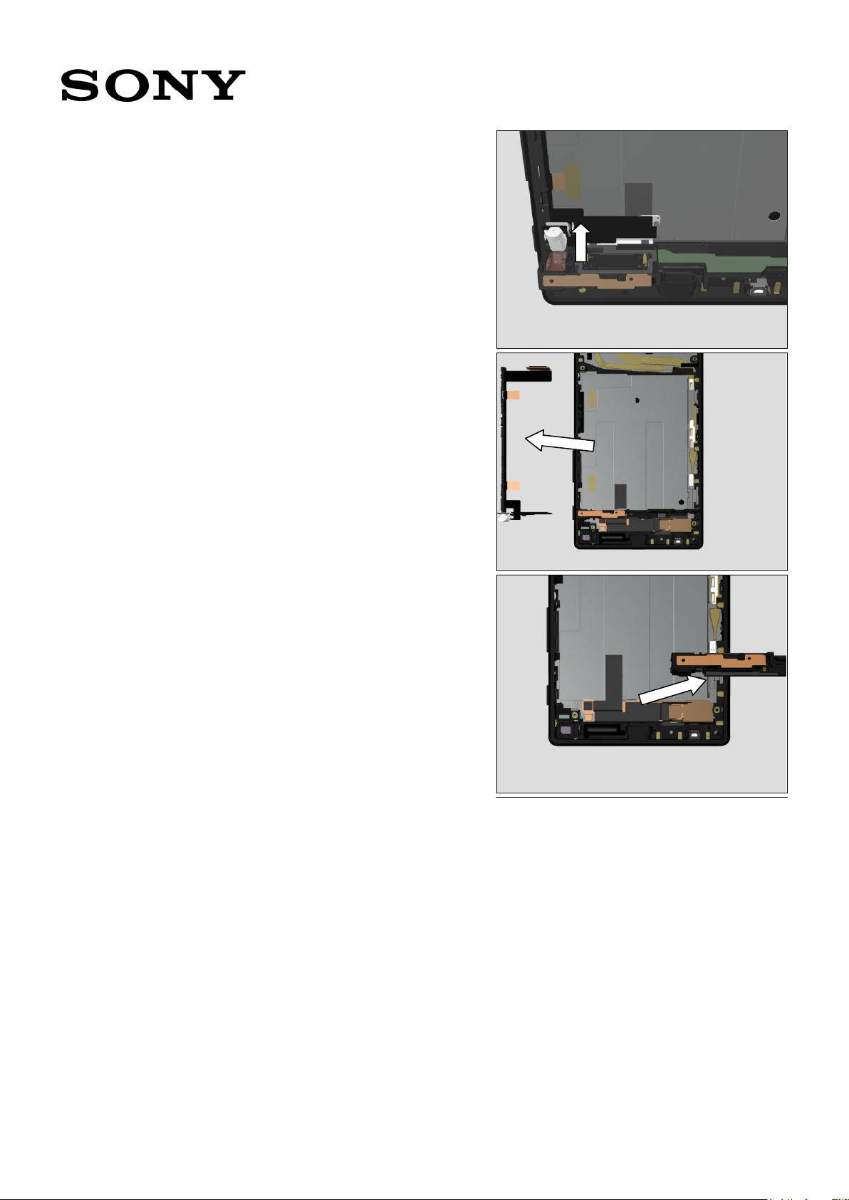
3.13 FPC Key
Remove the Sheet Conductive FPC Relay.
Working Instruction Repair Instruction Mechanical/E6603, E6653, E6633, E6683/
1300-3566 Rev 6
Sony Mobile Communications AB – Company Internal
18(64)
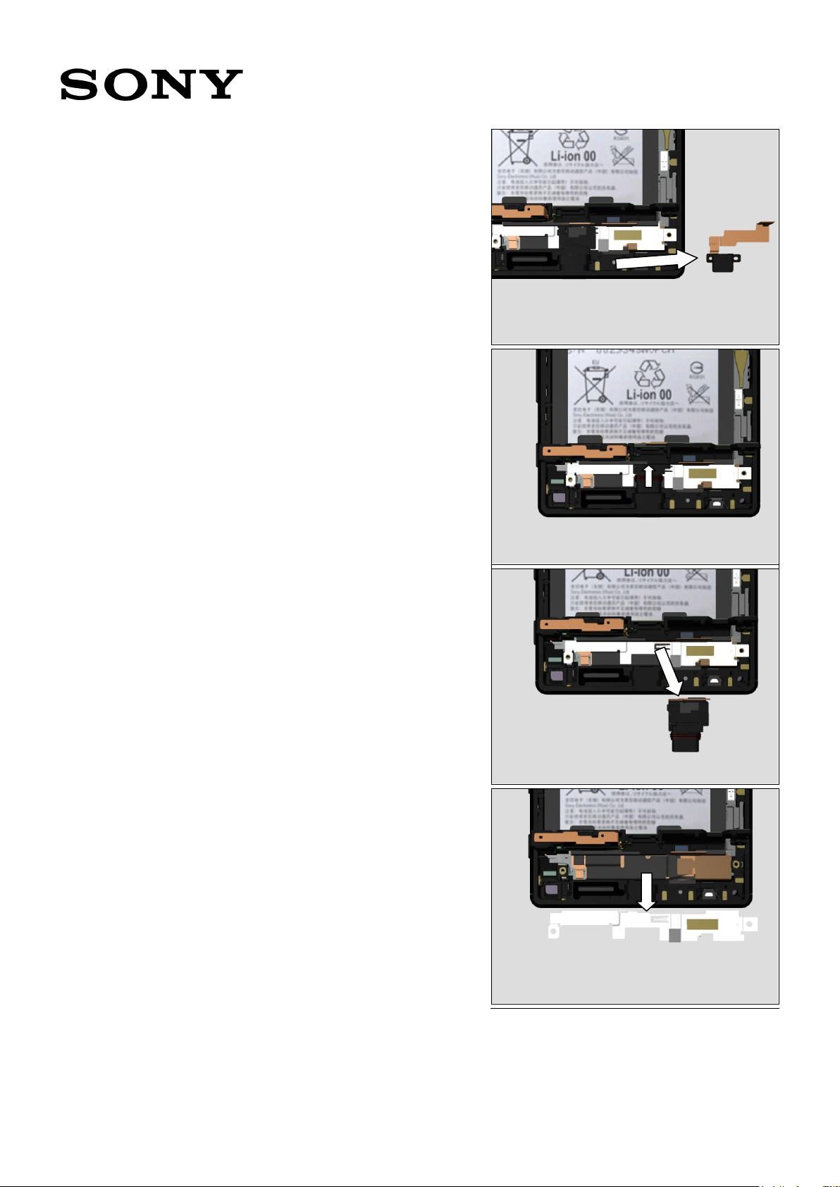
Remove the Plate Speaker and FPC area on the Speaker.
Remove the FPC Key.
3.14 Antenna Cell Main
Remove the Antenna Cell Main.
Working Instruction Repair Instruction Mechanical/E6603, E6653, E6633, E6683/
1300-3566 Rev 6
Sony Mobile Communications AB – Company Internal
19(64)
4.1 Antenna Cell Main &
Sheet Holder Speaker &
Cushion Battery Bottom
Follow the 3.1 – 3.14 Disassembly instructions!
Prepare the new Antenna Cell Main & Sheet Holder Speaker
& Cushion Battery Bottom.
Follow the 5.5, 13 – 30 Reassembly instructions!
Scrap! Sheet Holder Speaker & Cushion Battery Bottom
cannot be reused!
4.2 Antenna Cell Sub &
Gasket Conductive Sub
Camera
Follow the 3.1 – 3.2, 3.4 Disassembly instructions!
Prepare the new Antenna Cell Sub and Gasket Conductive
Sub Camera.
Follow the 5.16, 29 - 30 Reassembly instructions!
Scrap! Gasket Conductive Sub Camera cannot be
reused!
4.3 Antenna WiFi Sub
Follow the 3.1 – 3.7 Disassembly instructions!
Prepare the new Antenna WiFi Sub.
Follow the Removal instructions!
Follow the Installation instructions!
Follow the 5.13 – 16, 23, 29 -30 Reassembly instructions!
Working Instruction Repair Instruction Mechanical/E6603, E6653, E6633, E6683/
4 Replacement

1300-3566 Rev 6
Sony Mobile Communications AB – Company Internal
20(64)
REMOVAL
Remove the Antenna WiFi Sub.
INSTALLATION
Place the new Antenna WiFi Sub on the FPC Top.
4.4 Battery Embedded &
Adhesive Battery
Follow the 3.1 – 3.7, 11-12 Disassembly instructions!
Prepare the new Battery Embedded & Adhesive Battery.
Follow the 5.13 – 16, 23, 25 – 26, 29 - 30 Reassembly
instructions!
Scrap! Adhesive Battery cannot be reused!
4.5 Cap
Prepare the new Cap.
Remove the Cap.
Insert the new Cap in the cavity.
Scrap! Caps cannot be reused!
Working Instruction Repair Instruction Mechanical/E6603, E6653, E6633, E6683/
1300-3566 Rev 6
Sony Mobile Communications AB – Company Internal
21(64)
4.6 Cushion Main Camera
Follow the 3.1 - 2 Disassembly instructions!
Prepare the new Cushion Main Camera.
Remove the old Cushion Main Camera.
Follow the 5.29 - 30 Reassembly instructions!
Scrap! Cushion Main Camera cannot be reused!
4.7 Antenna NFC
Follow the 3.1 - 2 Disassembly instructions!
Prepare the new Antenna NFC.
Remove the old Antenna NFC.
Follow the 5.29 - 30 Reassembly instructions!
Scrap! Antenna NFC cannot be reused!
4.8 Camera Main & Holder
Main Camera & Cushion
BtoB A
Follow the 3.1 – 2, 5 Disassembly instructions!
Prepare the new Camera Main & Holder Main Camera &
Cushion BtoB A.
Follow the 5.23, 27, 29 - 30 Reassembly instructions!
Scrap! Cushion BtoB A cannot be reused!
4.9 Camera Sub & Holder
Sub Camera & Cushion
BtoB B
Follow the 3.1 – 2, 4, 6 Disassembly instructions!
Prepare the new Camera Sub & Holder Sub Camera &
Cushion BtoB B.
Follow the 5.15 - 16, 27, 29 - 30 Reassembly instructions!
Scrap! Cushion BtoB B cannot be reused!
Working Instruction Repair Instruction Mechanical/E6603, E6653, E6633, E6683/
1300-3566 Rev 6
Sony Mobile Communications AB – Company Internal
22(64)
4.10 FPC 1st Mic & Adhesive
FPC 1st Mic
Follow the 3.1 – 8 Disassembly instructions!
Prepare the FPC 1st Mic.
Follow the 5.9, 13 – 16, 23, 29 - 30 Reassembly instructions!
Scrap! Adhesive FPC 1st Mic cannot be reused!
4.11 FPC Key & Adhesive FPC
Speaker & Plate Speaker
& Sheet Conductive FPC
Relay
Follow the 3.1 –13 Disassembly instructions!
Prepare the new FPC Key & Adhesive FPC Speaker & Plate
Speaker & Sheet Conductive FPC Relay.
Follow the 5.8 - 9, 13 – 17,19 - 23, 26, 29 - 30 Reassembly
instructions!
Scrap! Adhesive FPC Speaker & Plate Speaker & Sheet
Conductive FPC Relay cannot be reused!
Working Instruction Repair Instruction Mechanical/E6603, E6653, E6633, E6683/

1300-3566 Rev 6
Sony Mobile Communications AB – Company Internal
23(64)
4.12 FPC Top & Adhesive
Audio Jack & Adhesive
Holder 2nd Mic &
Cushion Shade Audio
Jack & Holder 2nd Mic &
Sheet Holder 2nd Mic &
Sheet Shade Audio Jack
2
Follow the 3.1 – 7 Disassembly instructions!
Prepare new parts of above items.
Follow the Removal instructions!
Follow the Installation instructions!
Follow the 5.13 – 16, 23, 29 -30 Reassembly instructions!
Scrap! Adhesive Audio Jack & Adhesive Holder 2nd Mic
& Cushion Shade Audio Jack & Sheet Holder 2nd Mic &
Sheet Shade Audio Jack 2 cannot be reused!
Important! Noise Cancelling flashing must be performed
after replacing the FPC Top; 1289-2983 Trouble
Shooting Application – mechanical.
REMOVAL
Remove the Antenna WiFi Sub.
Insert and slide the Guitar Pick between the Audio Jack and
the Front Assy frame.
Working Instruction Repair Instruction Mechanical/E6603, E6653, E6633, E6683/

1300-3566 Rev 6
Sony Mobile Communications AB – Company Internal
24(64)
Remove the FPC Top.
Remove the Holder 2nd Mic.
INSTALLATION
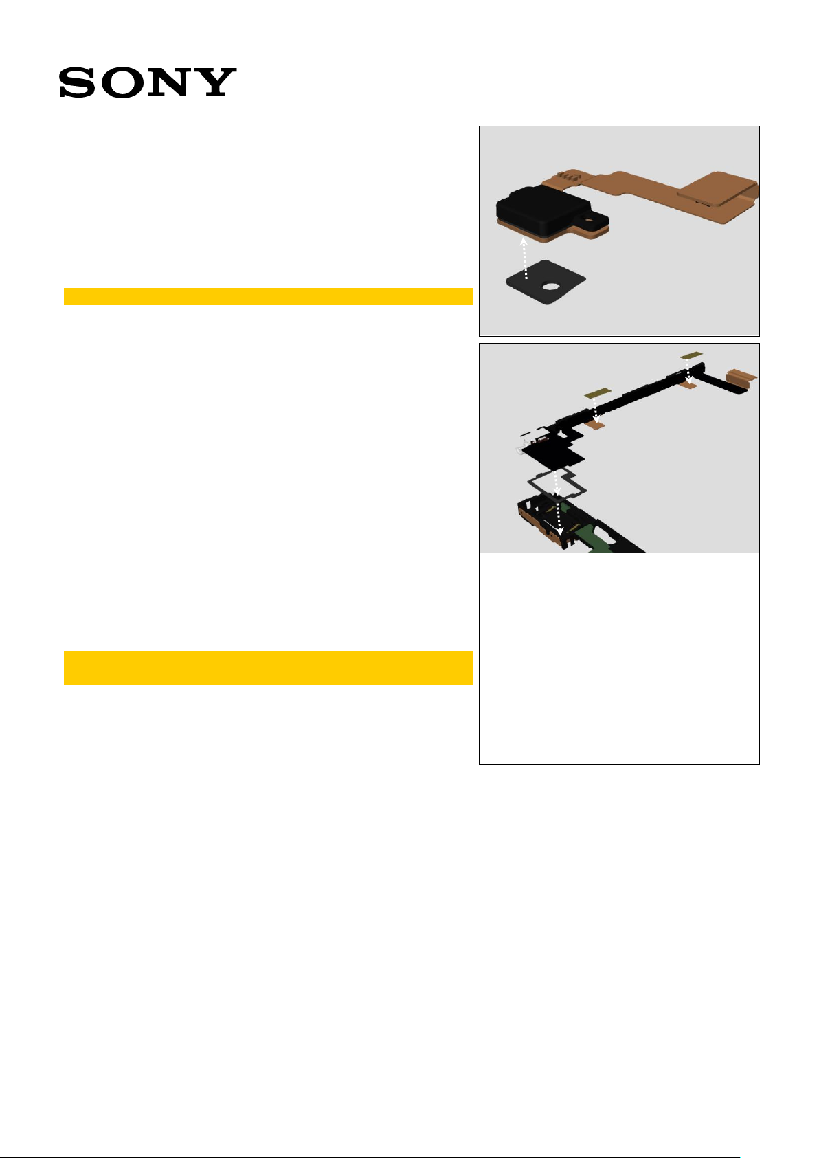
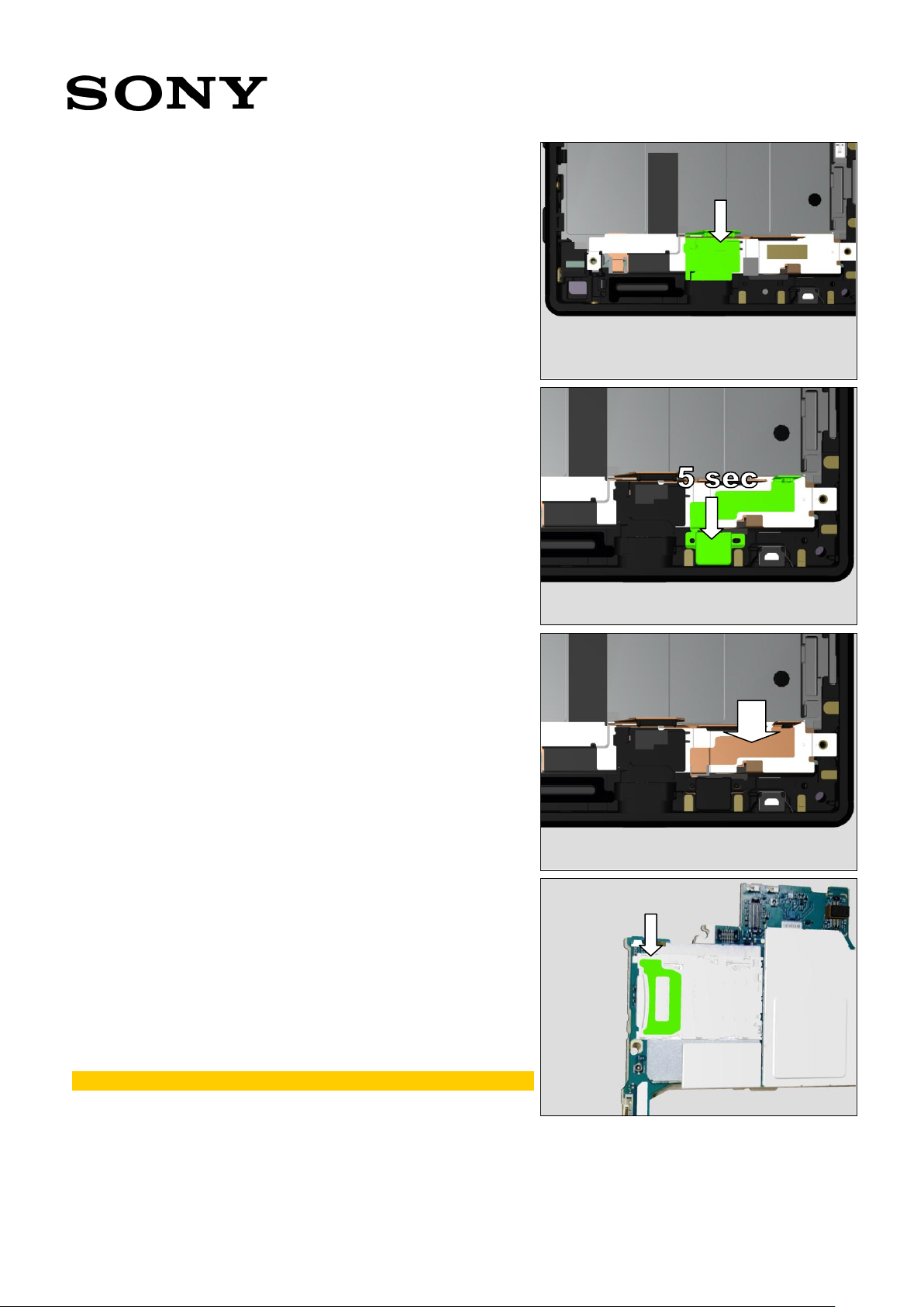
Attach the Adhesive Holder 2nd Mic.
Attach the Holder 2nd Mic.
Press with a finger for 5 sec.
Working Instruction Repair Instruction Mechanical/E6603, E6653, E6633, E6683/
1300-3566 Rev 6
Sony Mobile Communications AB – Company Internal
25(64)
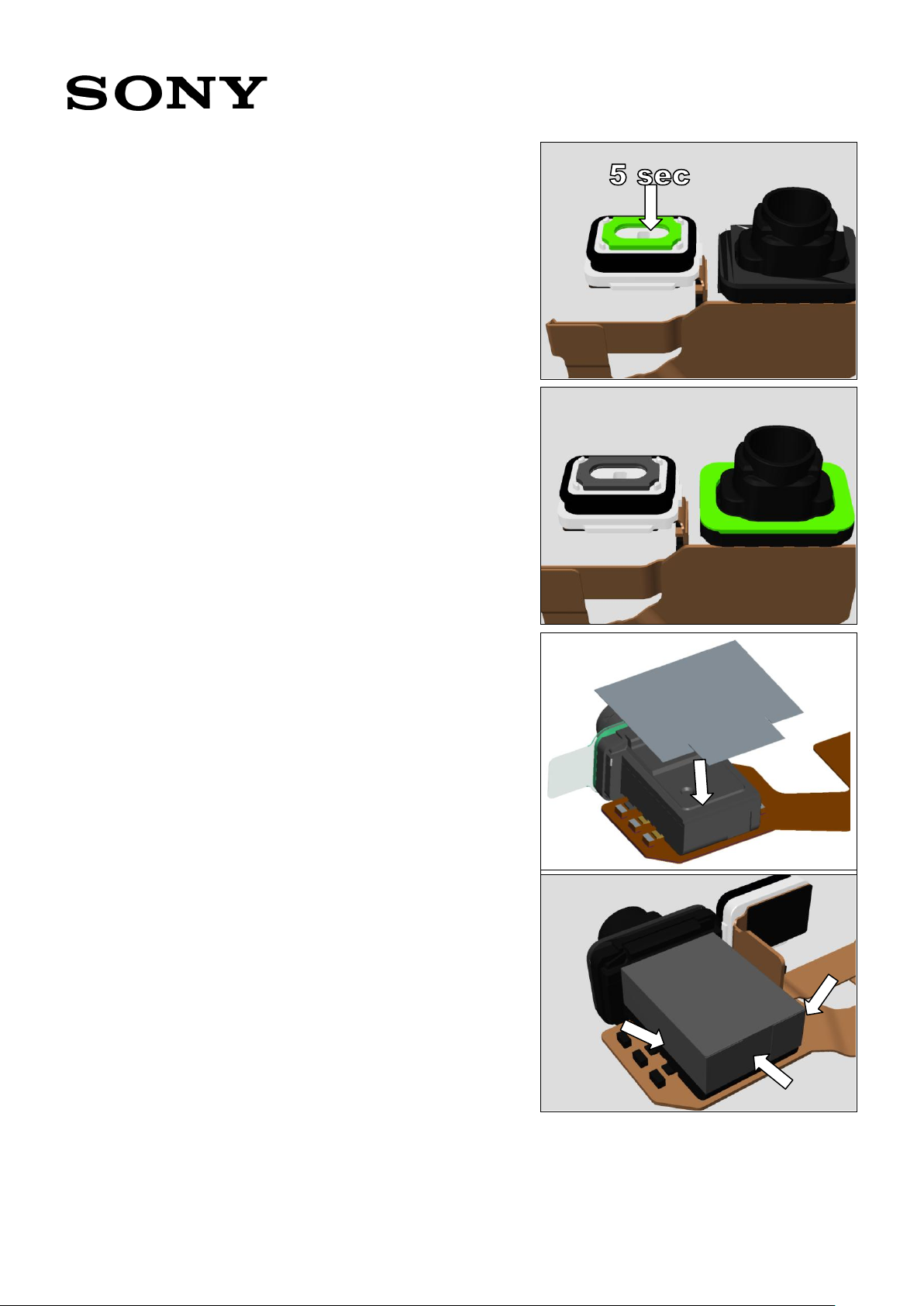
Attach the Sheet Holder 2nd Mic.
Gently press with a finger for 5 sec.
Inspect the sheet condition.
Attach the Adhesive Audio Jack.
Attach the Sheet Shade Audio Jack 2.
Fold the Sheet Shade Audio Jack 2 along the surface.
Working Instruction Repair Instruction Mechanical/E6603, E6653, E6633, E6683/

1300-3566 Rev 6
Sony Mobile Communications AB – Company Internal
26(64)
Attach the Cushion Shade Audio Jack.
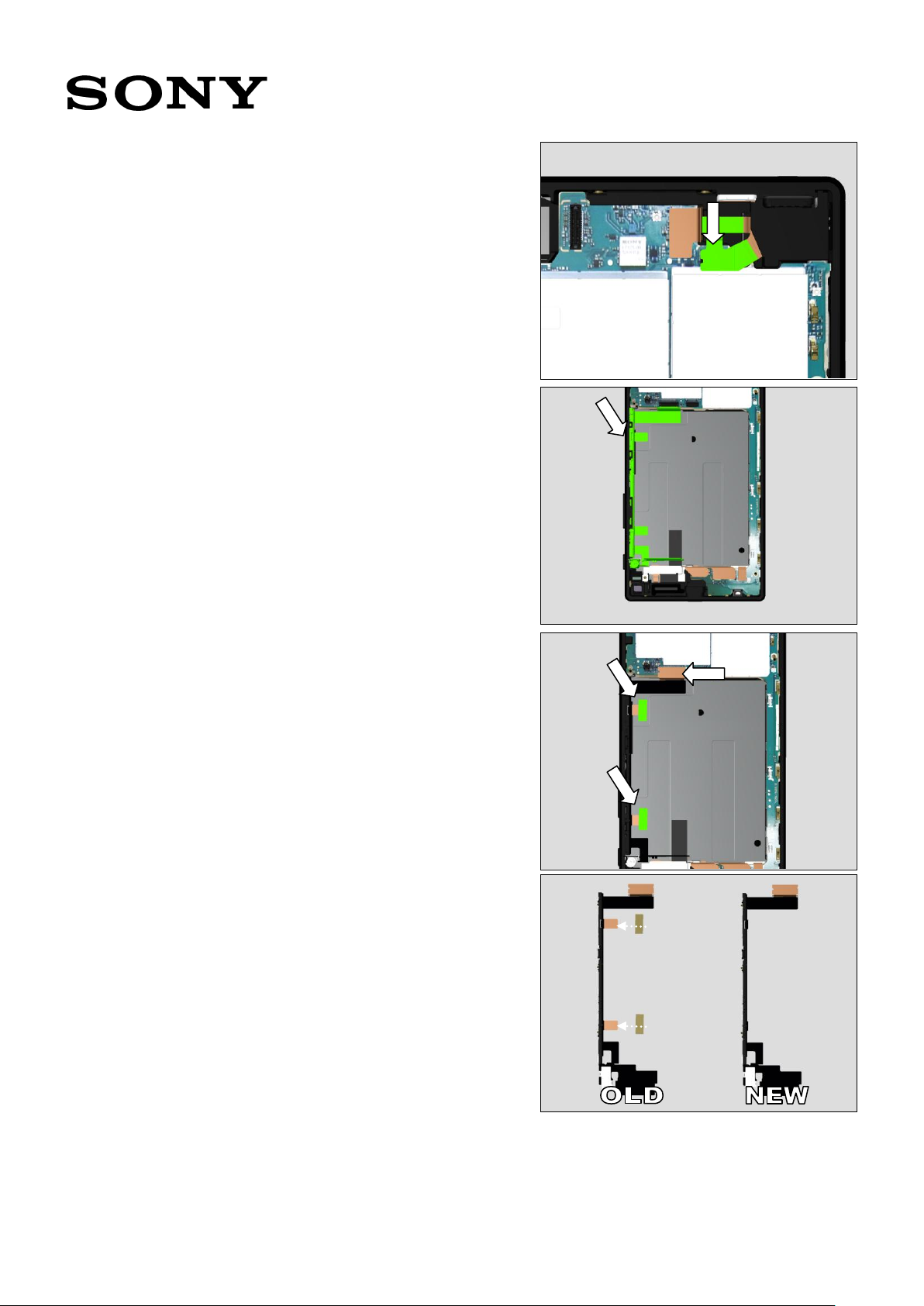
Insert the FPC Top in the cavity.
Press with FPC Jack Module Press for 10 sec.
Place the Antenna WiFi Sub.
Working Instruction Repair Instruction Mechanical/E6603, E6653, E6633, E6683/

1300-3566 Rev 6
Sony Mobile Communications AB – Company Internal
27(64)
4.13 FPC USB & Cushion
BtoB C & Sheet Spacer
USB
Follow the 3.1 – 7, 9 Disassembly instructions!
Prepare the new FPC USB & Cushion BtoB C & Sheet
Spacer USB.
Follow the 5.8, 13 – 16, 23, 27, 29 - 30 Reassembly
instructions!
Scrap! Cushion BtoB C & Sheet Spacer USB cannot be
reused!
4.14 Front Assy
Follow the 3.1 – 14 Disassembly instructions!
Prepare the new Front Assy
Follow the 5.1 – 9, 13 – 23, 25 – 26, 29 – 30 Reassembly
instructions!
Note! Thermal Gap Filler must be re-applied!
4.15 Gasket Conductive
Relay-U
Follow the 3.1 – 14 Disassembly instructions!
Prepare the new Gasket Conductive Relay-U.
Remove the old Gasket Conductive Relay-U.
Attach the new Gasket Conductive Relay-U.
Follow the 5.5, 8 – 9, 13 – 16, 23, 29 – 30 Reassembly
instructions!
Scrap! Gasket Conductive Relay-U cannot be reused!
Working Instruction Repair Instruction Mechanical/E6603, E6653, E6633, E6683/

1300-3566 Rev 6
Sony Mobile Communications AB – Company Internal
28(64)
4.16 Gasket Speaker Bottom
Follow the 3.1 – 2 Disassembly instructions!
Prepare the new Gasket Speaker Bottom.
Follow the Removal instructions!
Follow the 5.3, 29 – 30 Reassembly instructions!
Scrap! Gasket Speaker Bottom cannot be reused!
REMOVAL
Remove the two screws on the Antenna Cell Main.
Turn up the Antenna Cell Main.
Remove the old Gasket Speaker Bottom.
Working Instruction Repair Instruction Mechanical/E6603, E6653, E6633, E6683/
1300-3566 Rev 6
Sony Mobile Communications AB – Company Internal
29(64)
4.17 Holder PBA
Follow the 3.1 – 2 Disassembly instructions!
Prepare the new Holder PBA.
Remove the two screws and the holder PBA.
Follow the 5.14, 29 – 30 Reassembly instructions!
4.18 Holder Vib
Follow the 3.1 –13 Disassembly instructions!
Prepare the new Holder Vib.
Follow the 5.8 - 9, 13 – 17,19 - 23, 26, 29 - 30 Reassembly
instructions!
4.19 Label MoP
Prepare the new Label MoP printed.
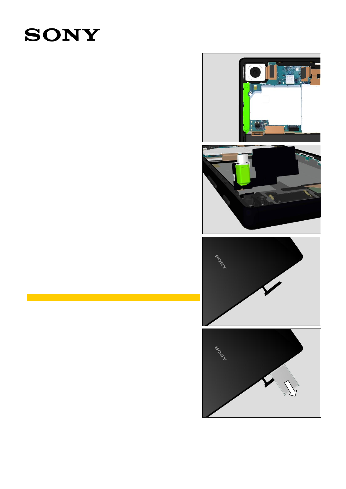
Open the Cap.
Scrap! Label MoP cannot be reused!
Pull out the Sheet Slider MoP.
Remove the old Label MoP
Working Instruction Repair Instruction Mechanical/E6603, E6653, E6633, E6683/
1300-3566 Rev 6
Sony Mobile Communications AB – Company Internal
30(64)
(For E6603, E6653)
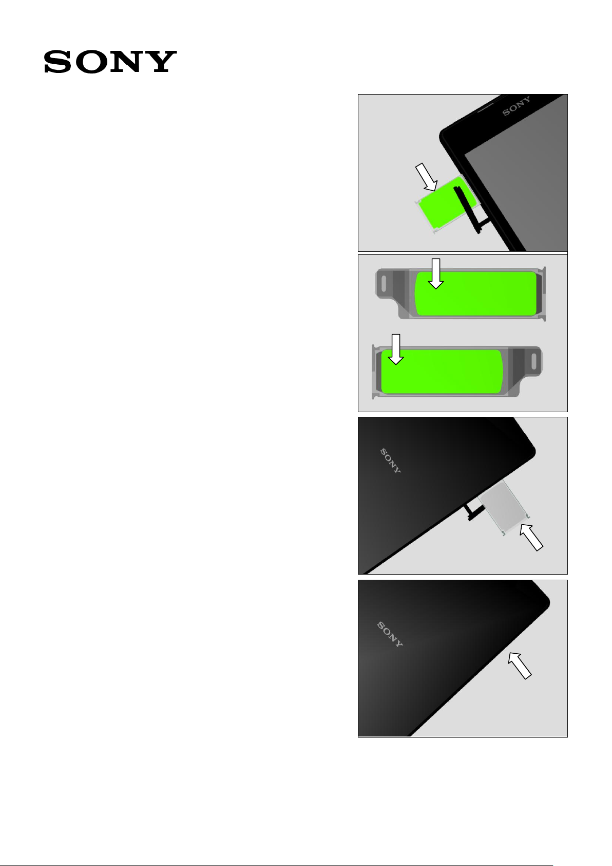
Attach the new Label MoP.
(For E6633, E6683)
Attach the new Label MoP.
Insert the Sheet Slider MoP.
Close the Cap.
Working Instruction Repair Instruction Mechanical/E6603, E6653, E6633, E6683/
1300-3566 Rev 6
Sony Mobile Communications AB – Company Internal
31(64)
4.20 Light Guide 3LED / Light
Guide 3LED Transparent
Follow the 3.1 – 7 Disassembly instructions!
Prepare the new Light Guide 3LED.
Remove the old Light Guide 3LED.
Follow the 4.12 Installation instructions!
Follow the 5.13 – 16, 23, 29 -30 Reassembly instructions!
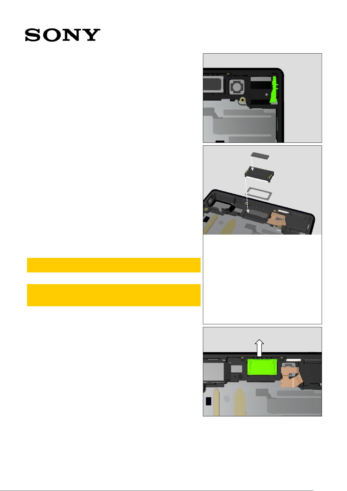
4.21 Loudspeaker & Adhesive
Ear Speaker & Cushion
ACO
Follow the 3.1 – 7 Disassembly instructions!
Prepare the new Loudspeaker & Adhesive Ear Speaker &
Cushion ACO.
Follow the Removal instructions!
Follow the Installation instructions!
Follow the 5.6, 13 – 16, 23, 29 -30 Reassembly instructions!
Scrap! Loudspeaker & Adhesive Ear Speaker & Cushion
ACO cannot be reused!
Important! After replacing the Loudspeaker, flash the
phone by Customize or Refurbish or SUCE (not SU) in
EMMA.
REMOVAL
Remove the old Loudspeaker.
Working Instruction Repair Instruction Mechanical/E6603, E6653, E6633, E6683/

1300-3566 Rev 6
Sony Mobile Communications AB – Company Internal
32(64)
INSTALLATION
Attach the new Adhesive Ear Speaker.
4.22 Panel Rear
Follow the 3.1 - 2 Disassembly instructions!
Prepare the new Panel Rear.
Follow the 5.28, 30 Reassembly instructions!
4.23 Adhesive Panel Rear
Follow the 3.1- 2 Disassembly instructions!
Prepare the new Adhesive Panel Rear.
Follow the 5.29 -30 Reassembly instructions!
Scrap! Adhesive Panel Rear cannot be reused!
4.24 RF Coax Cable
Follow the 3.1- 2 Disassembly instructions!
Prepare the new RF Coax Cable.
Remove the old RF Coax Cable.
Follow the 5.24, 29 -30 Reassembly instructions!
Working Instruction Repair Instruction Mechanical/E6603, E6653, E6633, E6683/

1300-3566 Rev 6
Sony Mobile Communications AB – Company Internal
33(64)
4.25 Sheet Conductive LCD
FPC A
Follow the 3.1- 12 Disassembly instructions!
Prepare the new Sheet Conductive LCD FPC A.
Remove the old Sheet Conductive LCD FPC A.
Follow the 5.4 – 5, 8 – 9, 13 – 16, 23, 26, 29 -30
Reassembly instructions!
Scrap! Sheet Conductive LCD FPC A cannot be reused!
4.26 Sheet Guide MoP
Follow the 3.1- 7 Disassembly instructions!
Prepare the new Sheet Guide MoP.
Remove the old Sheet Guide MoP.
Follow the 5.2, 13 – 16, 23, 29 -30 Reassembly instructions!
Scrap! Sheet Guide MoP cannot be reused!
(For E6603, E6653)
(For E6633, E6683)
4.27 Sheet Slider MoP
Follow the 3.1- 7 Disassembly instructions!
Prepare the new Sheet Slider MoP.
Follow the Removal instructions!
Follow the 5.2, 13 – 16, 23, 29 -30 Reassembly instructions!
Working Instruction Repair Instruction Mechanical/E6603, E6653, E6633, E6683/

1300-3566 Rev 6
Sony Mobile Communications AB – Company Internal
34(64)
REMOVAL
Peel off the adhesive area of the Sheet Guide MoP.
(For E6603, E6653)
(For E6633, E6683)
Remove the old Sheet Slider MoP.
(For E6603, E6653)
(For E6633, E6683)
Working Instruction Repair Instruction Mechanical/E6603, E6653, E6633, E6683/

1300-3566 Rev 6
Sony Mobile Communications AB – Company Internal
35(64)
4.28 Sheet WR Test
Follow the 3.1- 2 Disassembly instructions!
Prepare the new Sheet WR Test.
Remove the old Sheet WR Test.
Attach the new Sheet WR Test.
Scrap! Sheet WR Test cannot be reused!
4.29 Sheet ZIF LCD.
Follow the 3.1- 10 Disassembly instructions!
Prepare the new Sheet ZIF LCD.
Remove the old Sheet ZIF LCD.
Attach the new Sheet ZIF LCD.
Follow the 5.5, 8 – 9, 13 – 16, 23, 29 -30 Reassembly
instructions!
Scrap! Sheet ZIF LCD cannot be reused!
4.30 Shield Camera
Follow the 3.1- 7 Disassembly instructions!
Prepare the new Shield Camera.
Remove the old Shield Camera.
Follow the 5.7, 13 – 16, 23, 29 -30 Reassembly instructions!
4.31 Shield FPC LCD & Sheet
BtoB Touch
Follow the 3.1- 10 Disassembly instructions!
Prepare the new Shield FPC LCD.
Follow the 5.5, 8 – 9, 13 – 16, 23, 29 -30 Reassembly
instructions!
Scrap! Sheet BtoB Touch cannot be reused!
Working Instruction Repair Instruction Mechanical/E6603, E6653, E6633, E6683/

1300-3566 Rev 6
Sony Mobile Communications AB – Company Internal
36(64)
4.32 Spacer Panel Right
Follow the 3.1- 10 Disassembly instructions!
Follow the Removal instructions!
Prepare the new Spacer Panel Right.
Follow the Installation instructions!
Follow the 5.5, 7 – 9, 13 – 16, 23, 29 -30 Reassembly
instructions!
Scrap! Spacer Panel Right cannot be reused!
REMOVAL
Remove the Shield Camera.
Remove the Spacer Panel Right (Upper).
Turn up the Antenna Cell Main.
Working Instruction Repair Instruction Mechanical/E6603, E6653, E6633, E6683/
1300-3566 Rev 6
Sony Mobile Communications AB – Company Internal
37(64)
Remove the Spacer Panel Right (Lower).
INSTALLATION
Clamp the metal contact with the Spacer Panel Right.
Cut the extra area of the Spacer Panel Right.
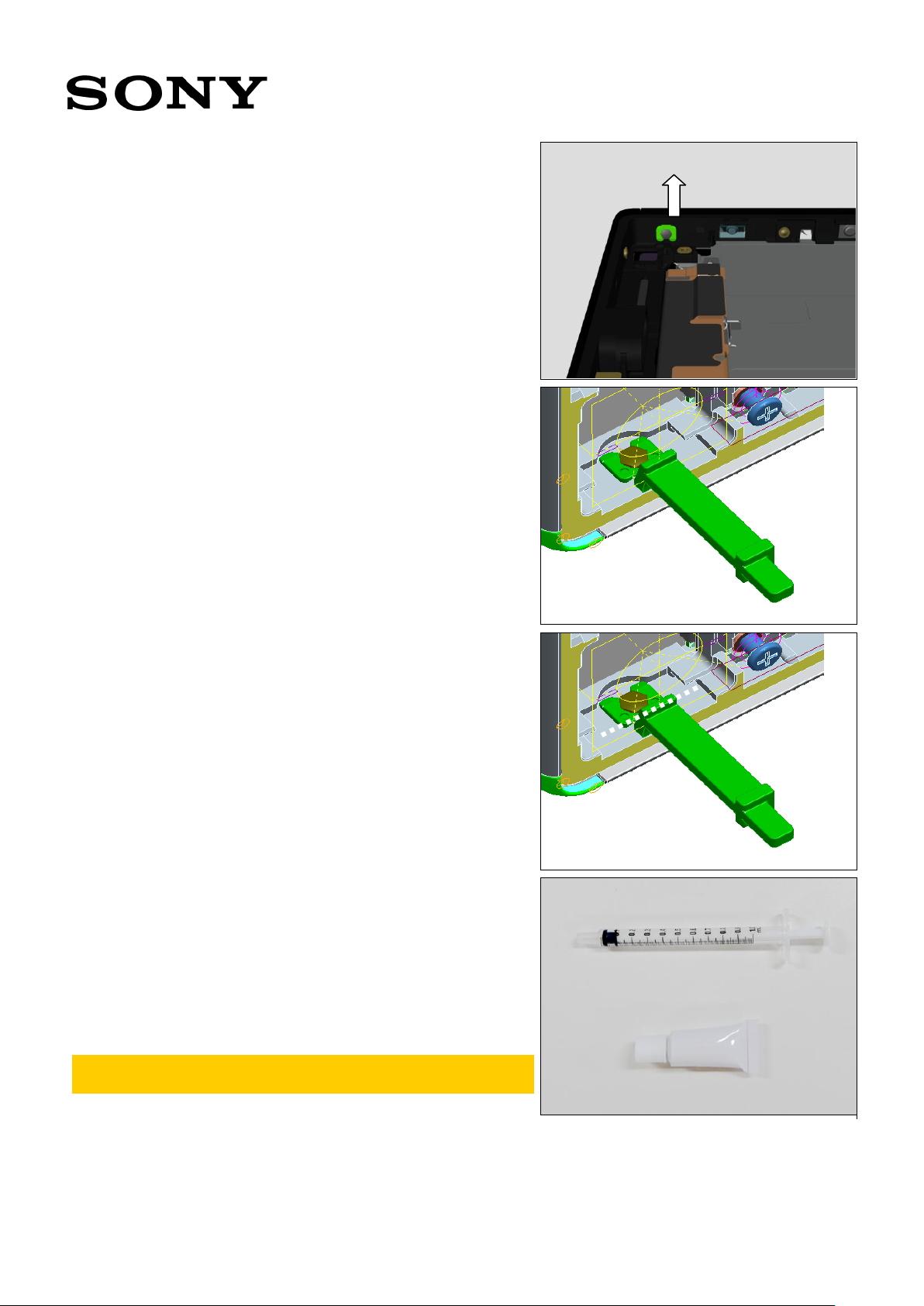
4.33 Thermal Gap Filler
Follow the 3.1 – 7 Disassembly instructions!
Prepare the new Thermal Gap Filler Tube & Thermal Gap
Filler Syringe.
Remove the Thermal Gap Filler.
Follow the 5.12 – 16, 23, 29 -30 Reassembly instructions!
Scrap! Thermal Gap Filler cannot be reused in case of
Front Assy replacement or Main PBA replacement!
Working Instruction Repair Instruction Mechanical/E6603, E6653, E6633, E6683/

1300-3566 Rev 6
Sony Mobile Communications AB – Company Internal
38(64)
In case of reuse, make sure that Thermal Gap Filler is left on
the Front Assy side.
Thermal Gap Filler left on the PBA side cannot be
reused!
Broken Thermal Gap Filler cannot be reused!
4.34 Top Speaker & Adhesive
Speaker Bottom
Follow the 3.1 –14 Disassembly instructions!
Prepare the new Top Speaker & Adhesive Speaker Bottom.
Follow the 5.8 - 9, 13 – 23, 26, 29 - 30 Reassembly
instructions!
Scrap! Top Speaker & Adhesive Speaker Bottom cannot
be reused!
Note! Part name comes from the naming in the past
model. This part is for lower speaker in this model.
Important! After replacing the Top Speaker, flash the
phone by Customize or Refurbish or SUCE (not SU) in
EMMA.
Working Instruction Repair Instruction Mechanical/E6603, E6653, E6633, E6683/

1300-3566 Rev 6
Sony Mobile Communications AB – Company Internal
39(64)
4.35 Tray Combo
Prepare the new Tray Combo.
Open the Cap.
Remove the old Tray Combo.
Insert the new Tray Combo.
Close the Cap
(For E6603, E6653)
(For E6633, E6683)
4.36 Water indicator
Follow the 3.1 – 14 Disassembly instructions!
Prepare the new Water indicator.
Remove the old Water indicator.
Attach the new Water indicator.
Follow the 5.5, 8 – 9, 13 – 16, 23, 29 – 30 Reassembly
instructions!
Scrap! Water indicator cannot be reused!
(For E6603, E6653)
Working Instruction Repair Instruction Mechanical/E6603, E6653, E6633, E6683/

1300-3566 Rev 6
Sony Mobile Communications AB – Company Internal
40(64)
(For E6633, E6683)
4.37 Main PBA & Cushion TGF
Lower/Upper/D & Sheet
Protection MoP Label –
Board Swap Replacement
Follow the 3.1 – 7 Disassembly instructions!
Prepare the Exchange PBA & Cushion TGF Lower/Upper/D
& Sheet Protection MoP Label.
Follow the 5.10 – 16, 23, 29 -30 Reassembly instructions!
Scrap! Cushion TGF Lower/Upper/D & Sheet Protection
MoP Label cannot be reused!
Note! Thermal Gap Filler must be re-applied!
Sheet Protection MoP Label is only for E6603, E6653.
Proximity, Noise Cancelling, Gyroscope and
Accelerometer Calibration and Color ID Flashing must
be performed for all replaced units; 1289-2983 Trouble
Shooting Application – mechanical.
(For E6603, E6653)
(For E6633, E6683)
4.38 Board Swap – Change
Label
CHANGE LABEL
Follow the instructions in the Generic Repair Manual –
Build swap for change of label.
Working Instruction Repair Instruction Mechanical/E6603, E6653, E6633, E6683/

1300-3566 Rev 6
Sony Mobile Communications AB – Company Internal
41(64)
4.39 Board Swap – Customize
of Software
CUSTOMIZE OF SOFTWARE
Follow the instructions in the Generic Repair Manual –
Build swap for customization of the software.
Working Instruction Repair Instruction Mechanical/E6603, E6653, E6633, E6683/
1300-3566 Rev 6
Sony Mobile Communications AB – Company Internal
42(64)
The reassembly is done in the following order:
1. Front Assy
2. Sheet Slider MoP
3. Gasket Speaker Bottom
4. Sheet Conductive LCD FPC A
5. Sheet BtoB Touch & Shield FPC LCD
6. Loudspeaker & Cushion ACO
7. Shield Camera
8. Sheet Spacer USB & FPC USB
9. FPC 1st Mic
10. Sheet Protection MoP Label
11. Sheet TGF Upper & Lower / Sheet TGF D
12. Thermal Gap Filler
13. Main PBA
14. Holder PBA
15. Holder Sub Camera & Camera Sub
16. Gasket Conductive Sub Camera & Antenna Cell Sub
17. FPC Key & Sheet Conductive FPC Relay
18. Sheet Holder Speaker & Adhesive Speaker Bottom &
Top Speaker
19. Adhesive FPC Speaker
20. Antenna Cell Main
21. Holder Vib
22. FPC Key 2 & Plate Speaker
23. Camera Main & Holder Main Camera
24. RF Coax Cable
25. Cushion Battery
26. Adhesive Battery & Battery Embedded
27. Cushion BtoB A & B & C
28. Antenna NFC
29. Adhesive Panel Rear
30. Panel Rear
5.1 Front Assy
Prepare the new Front Assy.
Working Instruction Repair Instruction Mechanical/E6603, E6653, E6633, E6683/
5 Reassembly
1300-3566 Rev 6
Sony Mobile Communications AB – Company Internal
43(64)
5.2 Sheet Slider MoP
(For E6603, E6653)
Open the adhesive area of the Sheet Guide MoP
Insert the Sheet Slider MoP.
Close the Sheet Guide MoP.
(For E6633, E6683)
Open the adhesive area of the Sheet Guide MoP D.
Insert the Sheet Slider MoP.
Close the Sheet Guide MoP D.
Working Instruction Repair Instruction Mechanical/E6603, E6653, E6633, E6683/

1300-3566 Rev 6
Sony Mobile Communications AB – Company Internal
44(64)
5.3 Gasket Speaker Bottom
Attach the new Gasket Speaker Bottom.
Press by Gasket WR SPK press for 5 sec.
5.4 Sheet Conductive LCD
FPC A
Remove the protection tape on the new Front Assy.
Attach the new Sheet Conductive LCD FPC A on the metal
plate area and FPC conductive area.
Working Instruction Repair Instruction Mechanical/E6603, E6653, E6633, E6683/

1300-3566 Rev 6
Sony Mobile Communications AB – Company Internal
45(64)
5.5 Sheet BtoB Touch &
Shield FPC LCD
Attach the new Sheet BtoB Touch on the Shield FPC LCD.
Place the Shield FPC LCD.
5.6 Loudspeaker & Cushion
ACO
Place the new Loudspeaker on the adhesive.
Press by Earspeaker/Loudspeaker Top Press Tool for 5 sec.
Working Instruction Repair Instruction Mechanical/E6603, E6653, E6633, E6683/

1300-3566 Rev 6
Sony Mobile Communications AB – Company Internal
46(64)
Attach the new Cushion ACO on the Loudspeaker.
5.7 Shield Camera
Place the Shield Camera in the cavity.
5.8 Sheet Spacer USB & FPC
USB
Attach the new Sheet Spacer USB on the FPC USB.
Target position is shown by the dotted line in the picture.
Working Instruction Repair Instruction Mechanical/E6603, E6653, E6633, E6683/
1300-3566 Rev 6
Sony Mobile Communications AB – Company Internal
47(64)
Insert the FPC USB in the cavity.
5.9 FPC 1st Mic
Attach the FPC 1st Mic on the Front Assy. Firmly press
black plastic area by a finger for 5 sec.
Press FPC area on the gold conductive film of the Shield
FPC LCD.
5.10 Sheet Protection MoP
Label
Attach the new Sheet Protection MoP Label on the combo
connector of the Main PBA.
Only for E6603, E6653!
Working Instruction Repair Instruction Mechanical/E6603, E6653, E6633, E6683/

1300-3566 Rev 6
Sony Mobile Communications AB – Company Internal
48(64)
5.11 Sheet TGF Upper &
Lower / Sheet TGF D
(For E6603, E6653)
Attach the new Sheet TGF Upper & Lower on the Main PBA
as shown in the picture.
(For E6633, E6683)
Attach the new Sheet TGF D on the Main PBA as shown in
the picture.
5.12 Thermal Gap Filler
Prepare the new Thermal Gap Filler Syringe and Thermal
Gap Filler Tube.
Open the embedded Thermal Gap Filler instruction in
Attachments and make sure to go through it prior to
use!
Working Instruction Repair Instruction Mechanical/E6603, E6653, E6633, E6683/

1300-3566 Rev 6
Sony Mobile Communications AB – Company Internal
49(64)
Confirm the expiration date that is stamped at the Thermal
Gap Filler Tube end.
Expiration date is 6 month after manufacturing.
X: Manufacturing Year (201X)
Y: Manufacturing Month (1,2,,,9, A, B, C)
Z: Manufacturing Date (1,2,,,9, A, B,,,,V)
Ex) Lot.59O = Manufacturing date is September 24th , 2015.
Material will start to set once it is exposed to air.
Scrap! Thermal Gap Filler Tube cannot be used 24h
after first opening.
Scrap! Thermal Gap Filler Syringe cannot be used 1h
after filling.
Open the tube with the cap head.
Working Instruction Repair Instruction Mechanical/E6603, E6653, E6633, E6683/

1300-3566 Rev 6
Sony Mobile Communications AB – Company Internal
50(64)
Inject contents of the tube from the end of the syringe.
Make sure the contents reach up to the tip of the syringe
and a small amount of the contents flows out as air is
released.
Wipe off the tip before using.
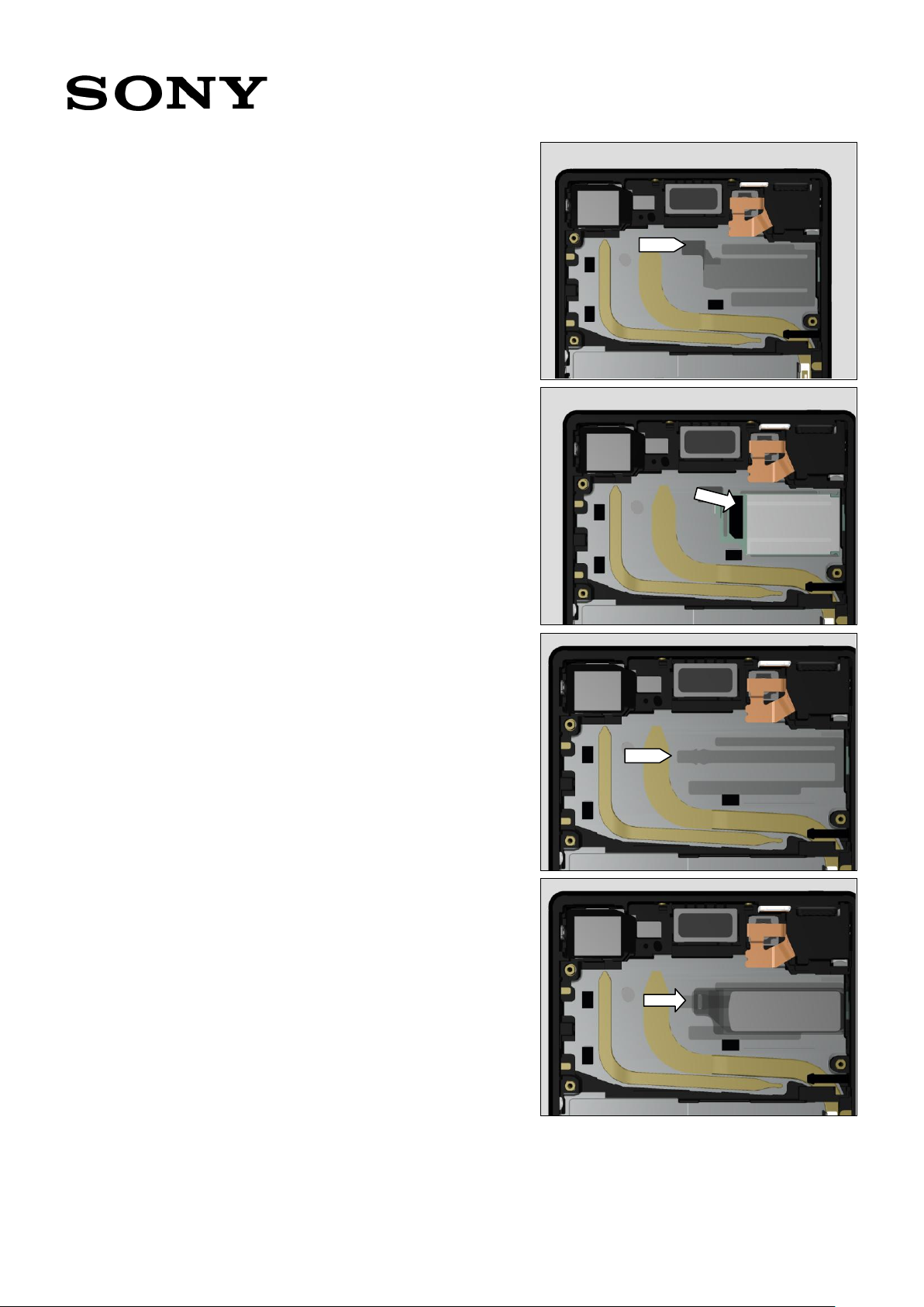
(For E6603, E6653)
Volume for one unit is 0.12 ml at one point.
Working Instruction Repair Instruction Mechanical/E6603, E6653, E6633, E6683/

1300-3566 Rev 6
Sony Mobile Communications AB – Company Internal
51(64)
Carefully apply the Thermal Gap Filler on the shown point.
Thermal Gap Filler must not cross the shaded area.
<Sample picture>
(For E6633, E6683)
Volume for one unit is 0.12 ml. 0.03 ml at each of four point.
Working Instruction Repair Instruction Mechanical/E6603, E6653, E6633, E6683/

1300-3566 Rev 6
Sony Mobile Communications AB – Company Internal
52(64)
Carefully apply the Thermal Gap Filler on the shown point.
Thermal Gap Filler must not cross the shaded area.
<Sample picture>
Wipe off the tip of the syringe until next repair.
Scrap! Do not refill the same syringe.
Working Instruction Repair Instruction Mechanical/E6603, E6653, E6633, E6683/

1300-3566 Rev 6
Sony Mobile Communications AB – Company Internal
53(64)
Next time you use, let a small amount of contents flow out
and wipe off the tip again.
REWORK
If the position or amount is not correct, wipe it off with a
cotton swab. pply the new Thermal Gap Filler.
Do inspection before applying Thermal Gap Filler.
Thermal Gap Filler is only allowed to be left at yellow ditch
up to 1mm width.
Do not let Thermal Gap Filler exceed the height of heat pipe.
Working Instruction Repair Instruction Mechanical/E6603, E6653, E6633, E6683/

1300-3566 Rev 6
Sony Mobile Communications AB – Company Internal
54(64)
5.13 Main PBA
Insert the Main PBA with around 30 degrees of an angle.
Main PBA assembling must be done immediately (within
5 minutes after Thermal Gap Filler applying).
(For E6603, E6653)
Tighten one screw on the right side of the PBA.
Len:2.6 Diam:1.4
Torque:13±1.3Ncm
(For E6633, E6683)
No screw here.
Connect three connectors (for USB, for LCD, for 1st Mic).
5.14 Holder PBA
Place the Holder PBA.
Tighten two screws.
Len:2.6 Diam:1.4
Torque:13±1.3Ncm
Working Instruction Repair Instruction Mechanical/E6603, E6653, E6633, E6683/

1300-3566 Rev 6
Sony Mobile Communications AB – Company Internal
55(64)
5.15 Holder Sub Camera &
Camera Sub
Attach the Holder Sub Camera on the Camera Sub.
Place the Camera Sub on the cavity.
Connect the Camera Sub connector.
5.16 Gasket Conductive Sub
Camera & Antenna Cell
Sub
Attach the new Gasket Conductive Sub Camera on the
Antenna Cell Sub.
Place the Antenna Cell Sub on the Main PBA.
Tighten the screw.
Len:2.6 Diam:1.4
Torque:13±1.3Ncm
Working Instruction Repair Instruction Mechanical/E6603, E6653, E6633, E6683/
1300-3566 Rev 6
Sony Mobile Communications AB – Company Internal
56(64)
Connect the FPC Top connector.
5.17 FPC Key & Sheet
Conductive FPC Relay
Place the new FPC Key.
Attach the new Sheet Conductive FPC Relays.
Connect the FPC Key Connector.
New version of FPC does not have the tabs. In that case
pasting the Sheet Conductive FPC Relay is not required.
Working Instruction Repair Instruction Mechanical/E6603, E6653, E6633, E6683/

1300-3566 Rev 6
Sony Mobile Communications AB – Company Internal
57(64)
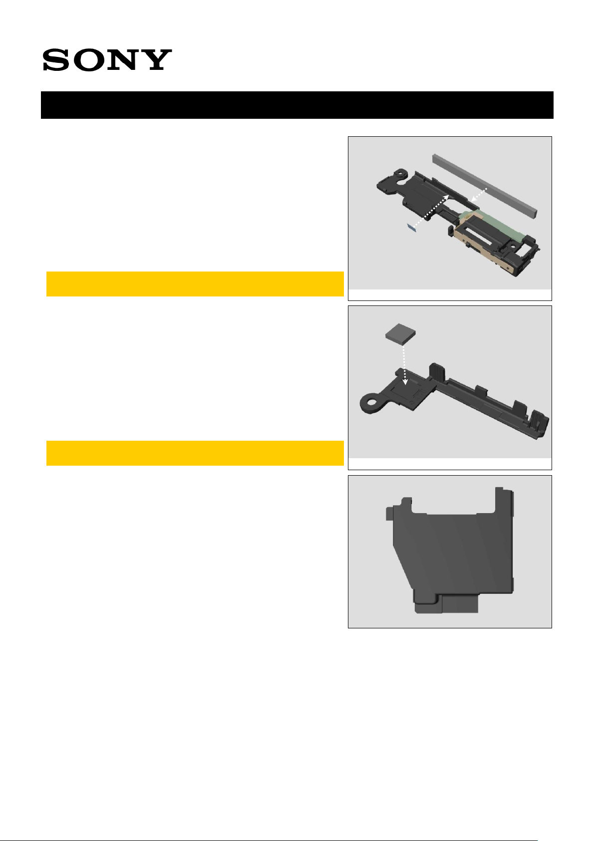
5.18 Sheet Holder Speaker &
Adhesive Speaker
Bottom & Top Speaker
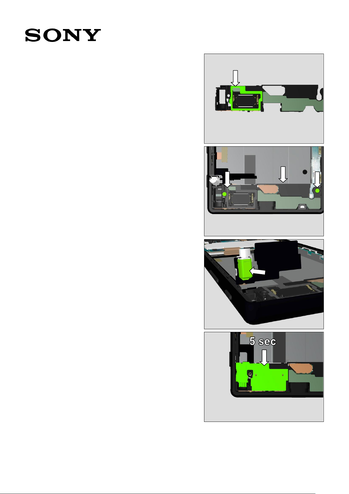
Attach the new Sheet Holder Speaker on the Antenna Cell
Main.
Attach the new Adhesive Speaker on the Antenna Cell Main.
Attach the Top Speaker on the Antenna Cell Main.
Press with Press Tool Ear Speaker for 5 sec.
Working Instruction Repair Instruction Mechanical/E6603, E6653, E6633, E6683/
1300-3566 Rev 6
Sony Mobile Communications AB – Company Internal
58(64)
5.19 Adhesive FPC Speaker
Attach the Adhesive FPC Speaker on the Antenna Cell
Main.
5.20 Antenna Cell Main
Place the Antenna Cell Main on the Front Assy.
Tighten two screws.
Len:2.6 Diam:1.4
Torque:13±1.3Ncm
5.21 Holder Vib
Place the Holder Vib on the vibrator.
5.22 FPC Key 2 & Plate
Speaker
Place FPC Key on the Adhesive FPC Speaker.
Firmly press with a finger for 5 sec.
Working Instruction Repair Instruction Mechanical/E6603, E6653, E6633, E6683/

1300-3566 Rev 6
Sony Mobile Communications AB – Company Internal
59(64)
Attach the Plate Speaker on the FPC Key.
5.23 Camera Main & Holder
Main Camera
Place the Camera Main.
Connect the Camera Main connector.
Place the Holder Main Camera on the Camera Main.
5.24 RF Coax Cable
Attach the RF Coax Cable on the Main PBA.
Working Instruction Repair Instruction Mechanical/E6603, E6653, E6633, E6683/

1300-3566 Rev 6
Sony Mobile Communications AB – Company Internal
60(64)
5.25 Cushion Battery
Attach the Cushion Battery on the Antenna Cell Main.
5.26 Adhesive Battery &
Battery Embedded
Attach the Adhesive Battery along the guide line.
Attach the Battery Embedded.
Press with a hand evenly for 5 sec.
Make sure the pull tabs peek between the Cushion
Battery and the Battery Embedded.
Connect the Battery connector.
Working Instruction Repair Instruction Mechanical/E6603, E6653, E6633, E6683/

1300-3566 Rev 6
Sony Mobile Communications AB – Company Internal
61(64)
5.27 Cushion BtoB A & B & C
Attach the new Cushion BtoB A.
Attach the new Cushion BtoB B.
Attach the new Cushion BtoB C.
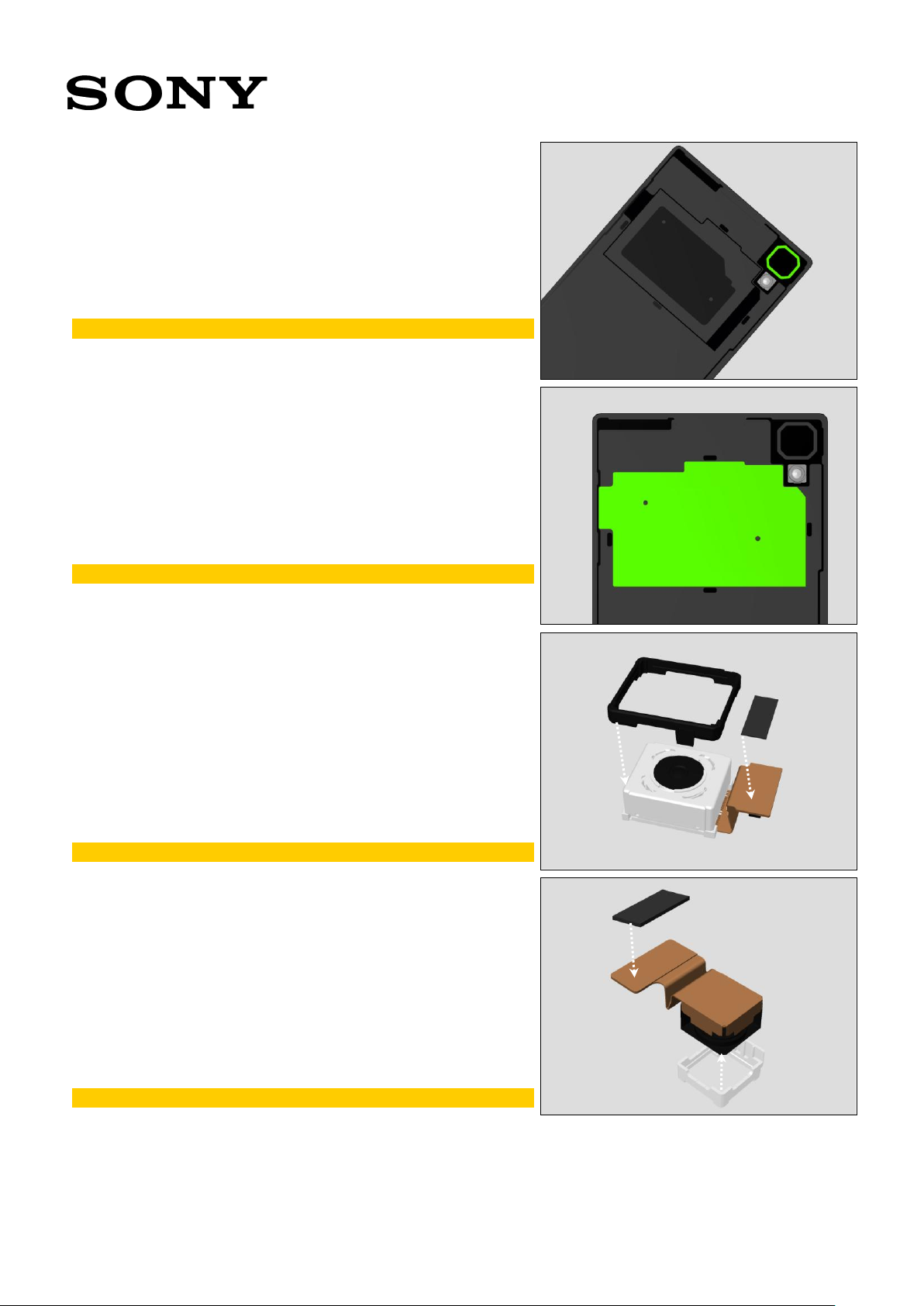
5.28 Antenna NFC
Attach the new Antenna NFC on the Panel Rear.
Press with a hand evenly for 5 sec.
Working Instruction Repair Instruction Mechanical/E6603, E6653, E6633, E6683/
1300-3566 Rev 6
Sony Mobile Communications AB – Company Internal
62(64)
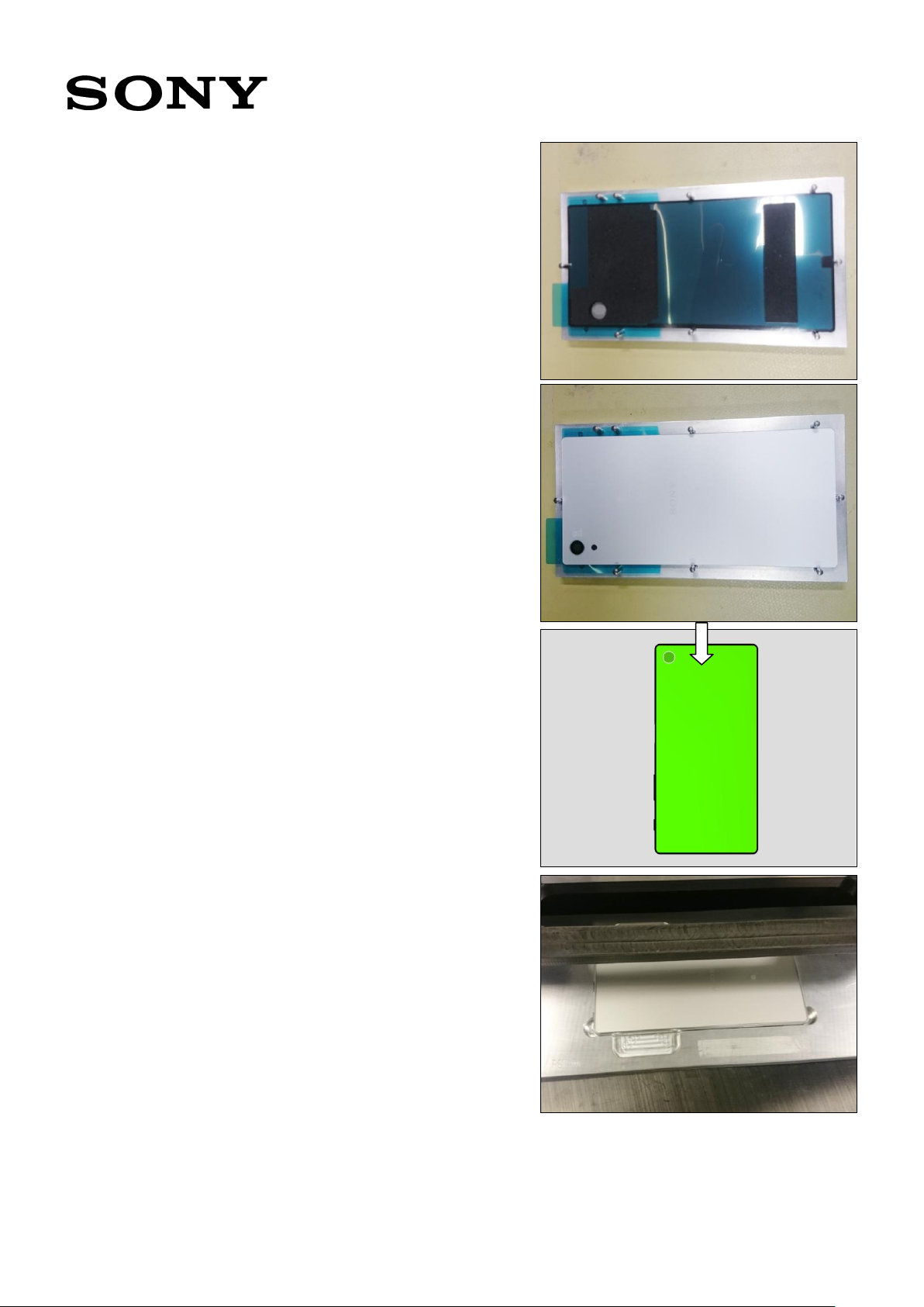
5.29 Adhesive Panel Rear
Place the Adhesive Panel Rear on the Rear Panel Adhesive
Alignment Fixture.
Attach the Adhesive Panel Rear.
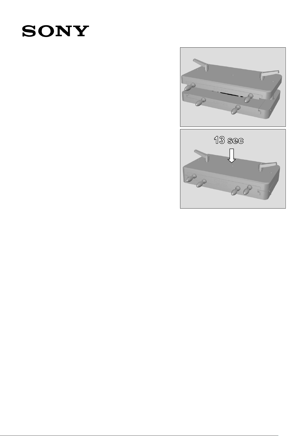
5.30 Panel Rear
Attach the Panel Rear on the phone unit.
Place the phone unit on the Bottom Press Inlay.
Working Instruction Repair Instruction Mechanical/E6603, E6653, E6633, E6683/
1300-3566 Rev 6
Sony Mobile Communications AB – Company Internal
63(64)
Insert the Bottom Press Inlay and the Rear Panel Press Top
Inlay in the Generic fixture for Press tool.
Press with the Bottom Press Inlay and the Rear Panel Press
Top Inlay for 13 sec with 512N±50.
Working Instruction Repair Instruction Mechanical/E6603, E6653, E6633, E6683/

1300-3566 Rev 6
Sony Mobile Communications AB – Company Internal
64(64)
Rev.
Date
Changes / Comments
1
2015-Sep-18
Initial release
2
2015-Sep-25
Add “Important!” description in 4.12, 21 and 34.
3
2015-Sep-30
Embedded Thermal Gap Filler instruction file in 5.12.
4
2015-Oct-23
Add Screw specification in 5.13, 14, 16, and 20.
Update Panel Rear press duration (10 to 13) in 5.30.
5
2015-Nov-17
Update Thermal Gap Filler tube picture in 5.12.
Update TGF instruction (embedded).
6
2016-May-6
Add description about new version of FPC Key in 5.17.
Working Instruction Repair Instruction Mechanical/E6603, E6653, E6633, E6683/
6 Revision History
 Loading...