


1286-2867 Rev 2
Sony Mobile Communications AB – Company Internal
Go/No Go Test
Xperia
TM
Z2
D6502, D6503, D6543, L50w
1286-2867 Rev 2
Sony Mobile Communications AB – Company Internal
2(8)
Test and Calibration Repair Instruction
CONTENTS
1 Go/No Go Testing ........................................................................... 3
1.1 Antenna Coupler D6502, D6503, D6543 and L50w no LTE ................ 3
1.2 Antenna Coupler D6503 D6543 all bands ........................................... 3
1.3 Attenuation Factors ............................................................................. 5
1.3.1 Loss Values – Antenna Coupler CMU-Z11 ................................................ 5
1.3.2 Loss Values – Antenna Coupler CMW-Z11 ................................................ 6
2 Revision History ............................................................................. 8
D6502 and L50w no LTE is ONLY implemented in SERPII.
D6503 no LTE is implemented in SERPII.
D6503 D6543 all bands is ONLY implemented in CMWrun
D6543 no LTE is implemented in SERPII.

1286-2867 Rev 2
Sony Mobile Communications AB – Company Internal
3(8)
For more information on Antenna Coupler and Cable in shield box testing, refer to
1220-1336: Generic Repair Manual – electrical, section ‘Setup Go/NoGo Test’!
For part no’s on the equipment below, refer to the ‘Tools Catalogue/Matrix’!
1.1 Antenna Coupler D6502, D6503,
D6543 and L50w no LTE
The following equipment has to be used:
Rohde & Schwartz RF Shield Package
- Rohde & Schwartz RF Shield Box CMU-Z11
- Rohde & Schwartz RF Coupler
- Grid Positioning Holder
RF Test Cable Flexible 1M
RF Adapter for RF Shield Box
Micro USIM Card, instrument specific
GSM-850/900/1800/1900
WCDMA-850/900/1700/1900/2100
Put the grid positioning holder with its reference point in
position F11 and place the phone as shown in the adjacent
picture.
A FEDB C G H I NMLJ K O P Q R
25
15
16
17
18
19
20
21
22
23
24
14
4
5
6
7
8
9
10
11
12
13
1
2
3
A FEDB C G H I NMLJ K O P Q R
25
15
16
17
18
19
20
21
22
23
24
14
4
5
6
7
8
9
10
11
12
13
1
2
3
1.2 Antenna Coupler D6503 D6543
all bands
The following equipment has to be used:
Rohde & Schwartz RF Shield Package
- Rohde & Schwartz RF Shield Box CMW-Z11
- Rohde & Schwartz RF Coupler
- Grid Positioning Holder
RF Test Cable Flexible 1M
RF Adapter for RF Shield Box
Micro USIM Card, instrument specific
GSM-850/900/1800/1900
WCDMA-850/900/1700/1900/2100
LTE-BAND 1/2/3/4/5/7/8/13/17/20
Put the grid positioning holder with its reference point in
position K11 and place the phone as shown in the adjacent
picture.
1 Go/No Go Testing
This Go/No Go testing has to be carried out with an:
Antenna Coupler.
Test and Calibration Repair Instruction
1286-2867 Rev 2
Sony Mobile Communications AB – Company Internal
4(8)
Test and Calibration Repair Instruction
Go/NoGo Testing
Follow the directions stated in ‘Go/NoGo Test Script Parameters’ to be found in
1220-1336: Generic Repair Manual – electrical, together with the ‘Attenuation Factors’ below!
This phone is available in 4 versions, D6502, D6503, D6543 and L50w, including the following bands:
D6502 and L50w:
GSM-850/900/1800/1900
WCDMA-850/ 900/1700/1900/2100
D6503:
GSM-850/900/1800/1900
WCDMA-850/ 900/1700/1900/2100
LTE-1/2/3/4/5/7/8/13/17/20 not to be tested in SERPII
D6543:
GSM-850/900/1800/1900
WCDMA-850/ 900/1700/1900/2100
LTE-1/2/3/4/5/7/8 not to be tested in SERPII
1286-2867 Rev 2
Sony Mobile Communications AB – Company Internal
5(8)
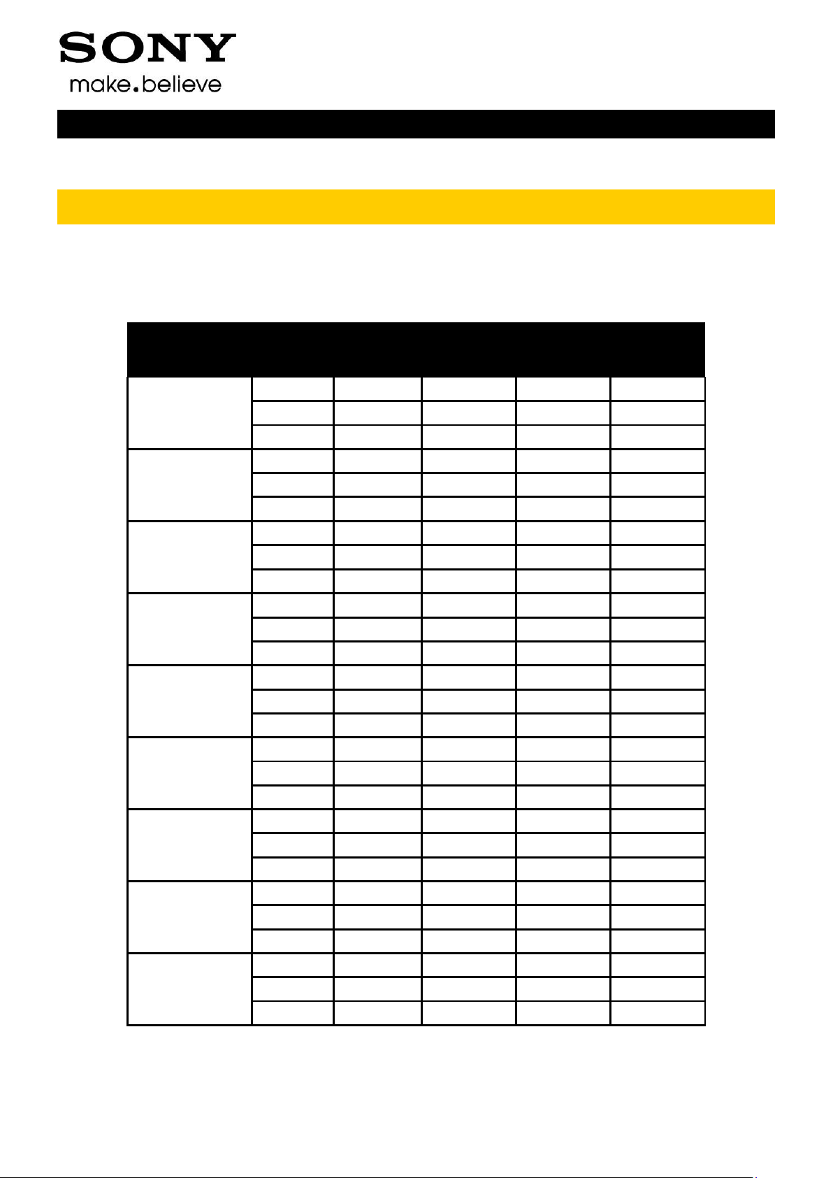
Attenuation
Attenuation
D6502 and L50w
D6503 and D6543
Band
Channel
Rx
Tx
Rx
Tx
GSM 850
Low
8.00
10.16
8.00
10.16
Mid
8.50
10.08
8.50
10.08
High
8.00
9.89
8.00
9.89
GSM 900
Low
7.00
11.28
7.00
11.28
Mid
10.00
10.22
10.00
10.22
High
12.00
8.94
12.00
8.94
GSM 1800
Low
16.00
15.36
16.00
15.36
Mid
16.00
14.64
16.00
14.64
High
16.00
15.50
16.00
15.50
GSM 1900
Low
15.50
16.46
15.50
16.46
Mid
16.00
17.35
16.00
17.35
High
16.00
15.85
16.00
15.85
WCDMA 850
Low
9.00
10.04
9.00
10.04
Mid
9.00
10.21
9.00
10.21
High
8.50
10.02
8.50
10.02
WCDMA 900
Low
8.00
7.63
8.00
7.63
Mid
8.00
7.19
8.00
7.19
High
9.00
7.09
9.00
7.09
WCDMA 1700
Low
16.00
14.95
16.00
14.95
Mid
16.50
14.53
16.50
14.53
High
17.00
14.39
17.00
14.39
WCDMA 1900
Low
16.00
14.81
16.00
14.81
Mid
15.00
17.04
15.00
17.04
High
17.00
15.59
17.00
15.59
WCDMA 2100
Low
15.50
13.04
15.50
13.04
Mid
16.50
12.03
16.50
12.03
High
18.50
12.72
18.50
12.72
Test and Calibration Repair Instruction
Go/NoGo Testing
1.3 Attenuation Factors
The attenuation values listed below in 1.3.1and 1.3.2 is valid only when the equipment listed on
the previous pages is being used!
1.3.1 Loss Values – Antenna Coupler CMU-Z11
1286-2867 Rev 2
Sony Mobile Communications AB – Company Internal
6(8)
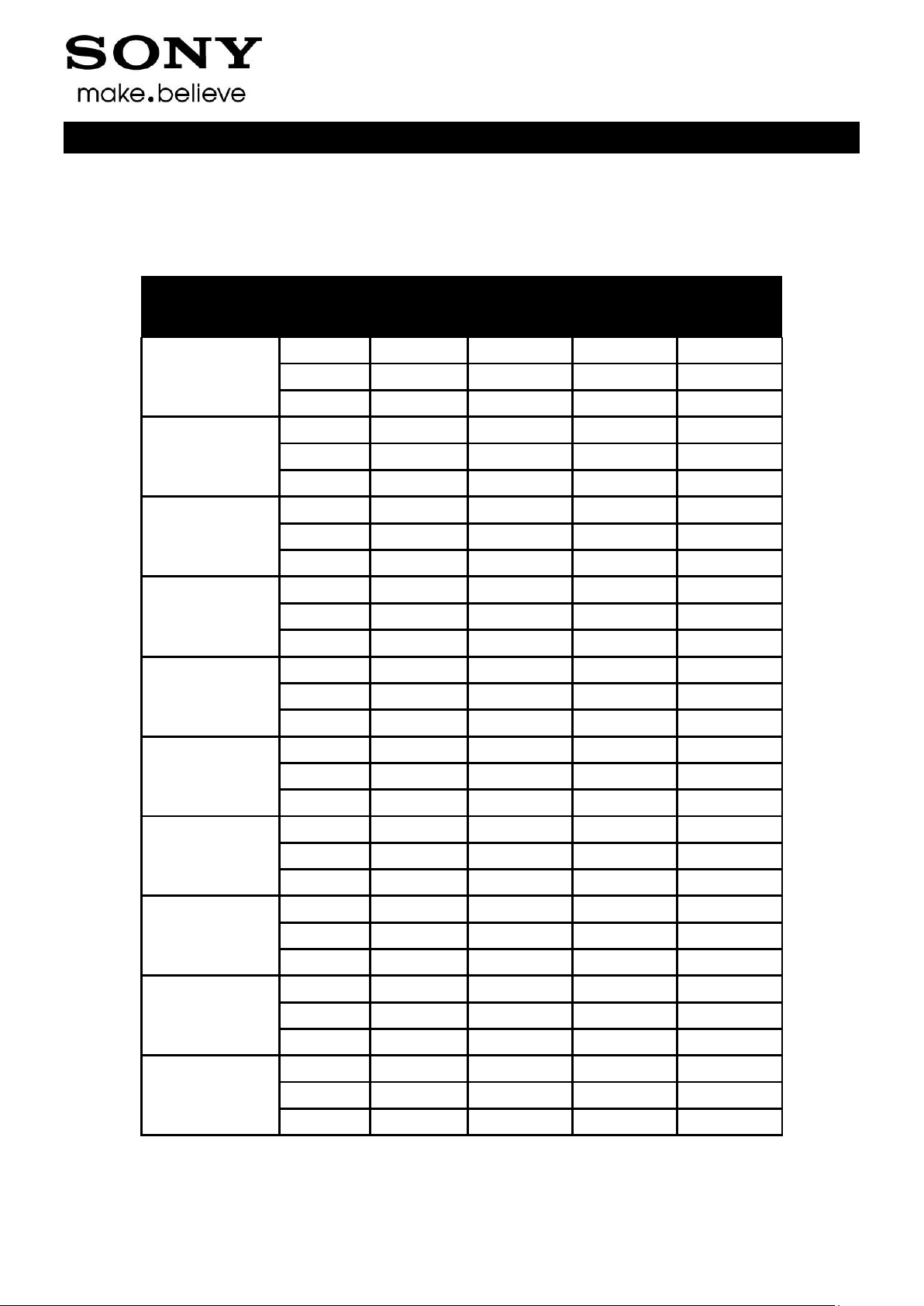
Attenuation
Attenuation
D6503
D6543
Band
Channel
Rx
Tx
Rx
Tx
GSM 850
Low
12.00
11.00
11.00
10.20
Mid
11.00
13.00
10.00
11.70
High
12.00
14.40
11.00
12.80
GSM 900
Low
19.00
11.50
17.00
10.30
Mid
19.00
12.30
17.00
11.10
High
15.00
15.00
14.00
13.50
GSM 1800
Low
11.00
13.00
12.00
15.60
Mid
11.00
11.30
11.00
13.10
High
11.00
11.00
13.00
12.20
GSM 1900
Low
16.00
10.00
16.00
10.70
Mid
19.00
11.00
16.00
13.00
High
21.00
12.40
17.00
14.00
WCDMA 850
Low
12.00
10.40
11.00
9.80
Mid
14.00
11.50
13.00
10.60
High
14.00
13.20
13.00
11.70
WCDMA 900
Low
21.00
10.00
19.00
8.70
Mid
21.00
11.40
19.00
10.00
High
19.00
14.60
17.00
12.70
WCDMA 1700
Low
15.00
13.60
19.00
17.40
Mid
14.00
13.20
16.00
16.40
High
12.00
12.40
13.00
14.30
WCDMA 1900
Low
17.00
10.00
18.00
10.40
Mid
22.00
11.00
17.00
13.60
High
24.00
12.40
20.00
13.60
WCDMA 2100
Low
15.00
13.20
19.00
13.70
Mid
12.00
17.30
15.00
17.30
High
12.00
19.20
14.00
15.00
LTE BAND 1
Low
14.00
15.00
16.00
16.00
Mid
13.00
17.30
15.00
17.30
High
12.00
20.00
13.00
20.00
Test and Calibration Repair Instruction
Go/NoGo Testing
1.3.2 Loss Values – Antenna Coupler CMW-Z11

1286-2867 Rev 2
Sony Mobile Communications AB – Company Internal
7(8)
LTE BAND 2
Low
16.00
11.00
17.00
12.00
Mid
19.00
11.60
17.00
13.60
High
17.00
13.30
17.00
15.00
LTE BAND 3
Low
11.00
15.50
21.00
15.50
Mid
10.00
13.50
11.00
13.50
High
10.00
12.60
13.00
12.70
LTE BAND 4
Low
15.00
15.50
16.00
15.50
Mid
14.00
15.50
16.00
17.30
High
11.00
15.00
12.00
15.40
LTE BAND 5
Low
12.00
13.00
11.00
11.60
Mid
11.00
14.00
10.00
12.20
High
11.00
14.50
11.00
13.00
LTE BAND 7
Low
23.00
25.00
24.00
25.00
Mid
20.00
24.50
24.00
24.50
High
18.00
26.00
24.00
26.00
LTE BAND 8
Low
20.00
11.50
17.00
11.00
Mid
19.00
12.50
17.00
12.00
High
17.00
15.10
15.00
14.00
LTE BAND 13
Low
13.00
11.00
Mid
13.00
11.00
High
13.00
11.00
LTE BAND 17
Low
12.00
13.20
Mid
13.00
13.00
High
12.00
13.00
LTE BAND 20
Low
10.00
13.50
Mid
10.00
15.00
High
11.00
15.00
Test and Calibration Repair Instruction
Go/NoGo Testing: Attenuation Factors

1286-2867 Rev 2
Sony Mobile Communications AB – Company Internal
8(8)
Rev.
Date
Changes / Comments
1
2014-03-13
Initial release
2
2014-04-06
Added D6543.
2 Revision History
Test and Calibration Repair Instruction
 Loading...