

Sony Xperia T2 Ultra Dual D5322, Xperia T2 Ultra D5303, Xperia T2 Ultra D5306 Working Instructions
1282-8956 Rev 1
©
Sony Mobile Communications AB – Company Internal
Working Instructions
- mechanical -
Xperia
T
M
T2 Ultra Dual D5322, XM50h
Xperia
TM
T2 Ultra D5303,D5306, XM50t

Working Instructions (mech)
1282-8956 Rev 1
©
Sony Mobile Communications AB – Company Internal
2(73)
CONTENTS
1Exterior Views ................................................................................. 4
1.1 D5322, XM50h,D5303, D5306, XM50t ................................................... 4
2Tools ................................................................................................ 5
3Disassembly.................................................................................... 6
3.1 SIM Tray ................................................................................................ 6
3.2 Battery Cover Assy .............................................................................. 7
3.3 Rear Cover Assy .................................................................................. 7
3.4 Label Tray ............................................................................................. 9
3.5 FPC SIM (Dual & Single) ...................................................................... 9
3.6 Main PBA ............................................................................................ 11
3.7 Battery and Display Assy .................................................................. 15
4Replacement ................................................................................. 16
4.1 Battery Cover Assy ............................................................................ 16
4.2 Battery ................................................................................................. 16
4.3 Camera 13 MPixel CMOS ................................................................... 16
4.4 FPC SIM Dual/ FPC SIM Single .......................................................... 16
4.5 Rear Cover Assy ................................................................................ 17
4.6 SIM Tray .............................................................................................. 17
4.7 Adhesive Audio Jack & FPC Audio Jack .......................................... 18
4.8 Adhesive Battery FPC ........................................................................ 21
4.9 Adhesive Relay FPC Single Side....................................................... 22
4.10 Adhesive Main Ant PBA & PBA Main Antenna................................. 23
4.11 Adhesive Main FPC Single Side & FPC Relay .................................. 26
4.12 Adhesive Sub Ant PBA & PBA 2nd Main Antenna XM50t (Only for
XM50t) ................................................................................................. 30
4.13 Adhesive Vibrator & Vibrator ............................................................ 33
4.14 Bracket Assy Block 2nd SIM (D5303, D5306, XM50t) ....................... 35
4.15 Bracket Assy Panel Right .................................................................. 36
4.16 Cable antenna_cable .......................................................................... 37
4.17 Camera Chat ....................................................................................... 39
4.18 Camera Lens Adhesive & Window Camera ...................................... 40
4.19 Cap SD ................................................................................................ 41
4.20 Cap SIM Single (D5303, D5306, XM50t)/ Cap SIM Dual (D5322,
XM50h) ................................................................................................ 43
4.21 Display Assy ....................................................................................... 45
4.22 Earspeaker & Gasket Receiver .......................................................... 46
4.23 Flash Lens and Flash Lens Adhesive ............................................... 48
4.24 Label & Foil 0.0 mm CU label Tray .................................................... 50

Working Instructions (mech)
1282-8956 Rev 1
©
Sony Mobile Communications AB – Company Internal
3(73)
4.25 Foil 0.0 mmBattery Right ................................................................... 52
4.26 Gasket Conductive Relay FPC Speaker Gasket ............................... 53
4.27 Gasket Conductive Relay FPC Vib Gasket ....................................... 54
4.28 Gasket Speaker & Loudspeaker ........................................................ 55
4.29 Key Camera & Key Volume & Bracket Assy Panel Key ................... 57
4.30 Key On/Off & MComp Assy Ring Power ........................................... 58
4.31 Speaker Mesh ..................................................................................... 60
4.32 Main Camera Ring & Main Camera Ring Adhesive .......................... 61
4.33 Board Swap – Replacement .............................................................. 62
4.34 Board Swap – Change Label ............................................................. 62
4.35 Board Swap – Customize of Software .............................................. 62
5Reassembly................................................................................... 63
5.1 Battery & Display Assy ...................................................................... 63
5.2 Main PBA ............................................................................................ 64
5.3 FPC SIM (Dual or Single) ................................................................... 67
5.4 Label Tray ........................................................................................... 69
5.5 Rear Cover Assy ................................................................................ 69
5.6 Battery Cover Assy ............................................................................ 71
5.7 SIM Tray .............................................................................................. 72
6Revision History ........................................................................... 73
For general information about mechanical repair related issues, refer to
1220-1333: Generic Repair Manual - mechanical
Always firstly disconnect the Battery FPC BtB connector to cut off power supply when the
Antenna NFC Assy is disassembled.
Always finally connect the Battery FPC BtB connector before the Antenna NFC Assy is
reassembled.
Working Instructions (mech)
1282-8956 Rev 1
©
Sony Mobile Communications AB – Company Internal
4(73)
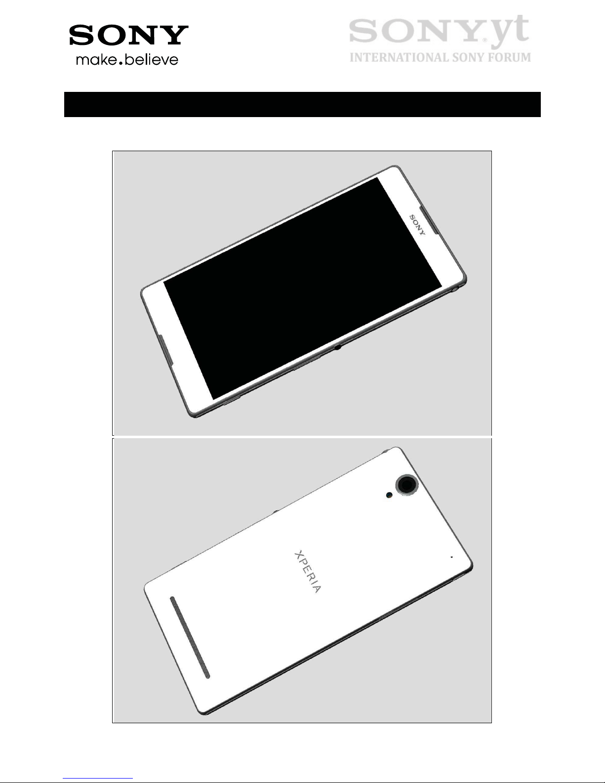
1 Exterior Views
1.1 D5322, XM50h,D5303, D5306, XM50t
Working Instructions (mech)
1282-8956 Rev 1
©
Sony Mobile Communications AB – Company Internal
5(73)
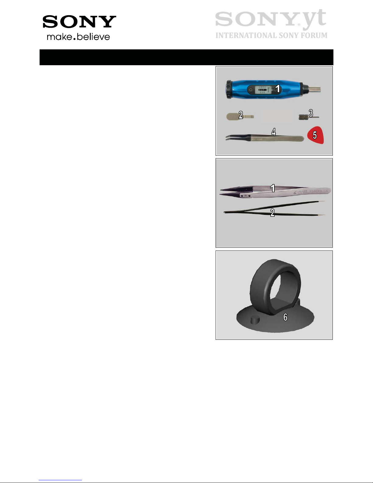
2 Tools
1. Torque Screwdriver
2. Front Opening Tool
3. Bits (JCIS No 0)
4. Flex Film Assembly Tool
5. Guitar Pick
STANDARD TOOLS
1. Plastic Tweezers
2. Pointed-tip Tweezers
6. Suction cup
Working Instructions (mech)
1282-8956 Rev 1
©
Sony Mobile Communications AB – Company Internal
6(73)
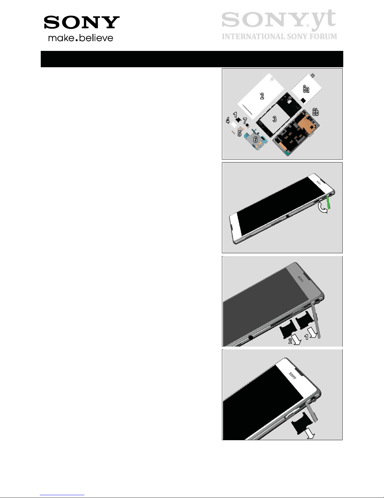
3 Disassembly
The disassembly is done in the following order:
1. SIM Tray
2. Battery Cover Assy
3. Rear Cover Assy
4. Label Tray
5. FPC SIM
6. Main PBA
7. Main Camera
8. Battery (a) & Display Assy (b)
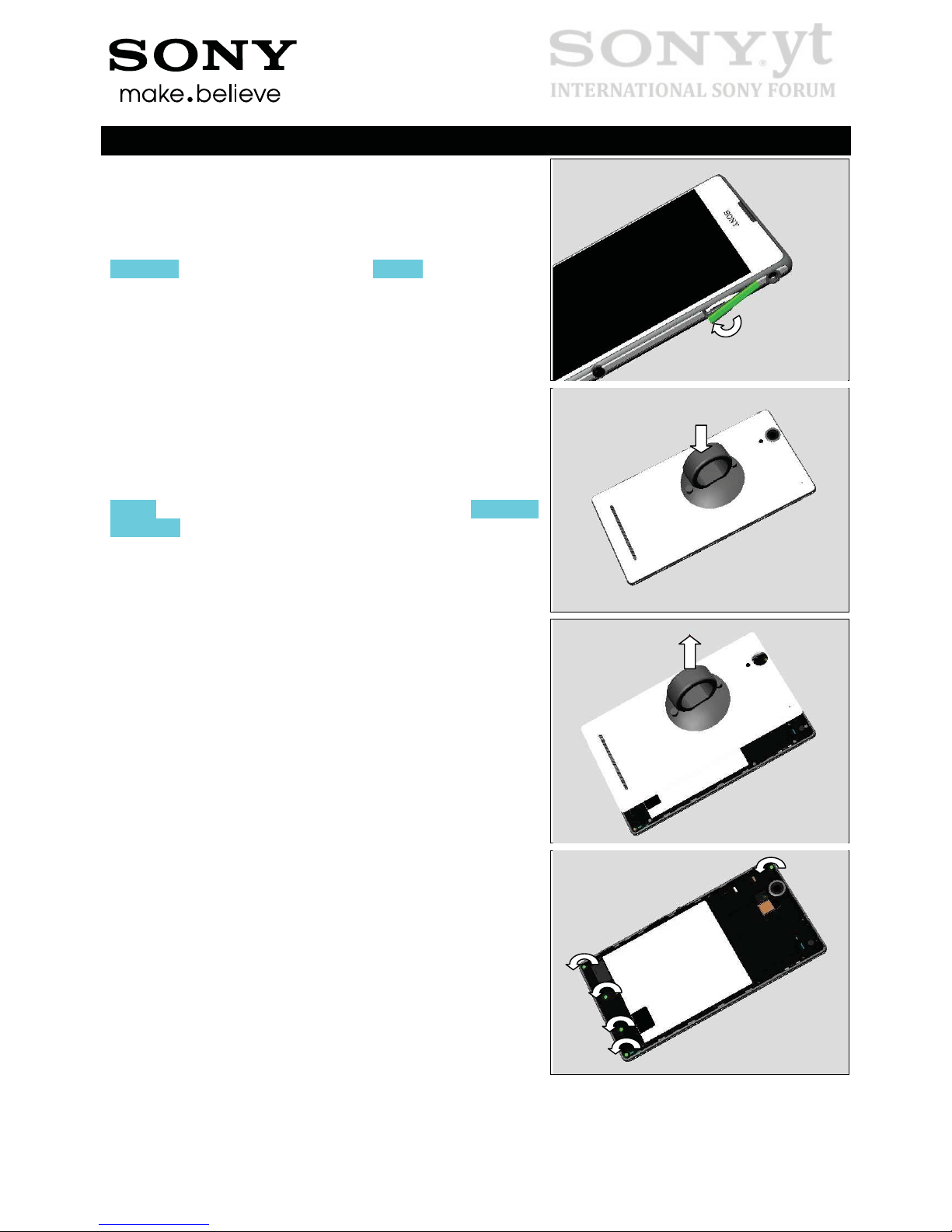
3.1 SIM Tray
Open the Cap SIM Singe or Cap SIM Dual by fingers.
(For D5322, XM50h)
Remove two SIM Trays.
(For D5303, D5306, XM50t)
Remove SIM Tray.
Working Instructions (mech)
1282-8956 Rev 1
©
Sony Mobile Communications AB – Company Internal
7(73)
Disassembly
Close the Cap SIM Dual or Cap SIM Single.
3.2 Battery Cover Assy
Attach the Suction Cup on the Battery Cover Assy as shown
in picture.
Pull upwards to release the hooks of Battery Cover Assy
and remove the Battery Cover Assy.
3.3 Rear Cover Assy
Remove the five Screws 1.4X3.5 (1262-1965) by using a
screwdriver with Bits (JCIS No 0).
Working Instructions (mech)
1282-8956 Rev 1
©
Sony Mobile Communications AB – Company Internal
8(73)
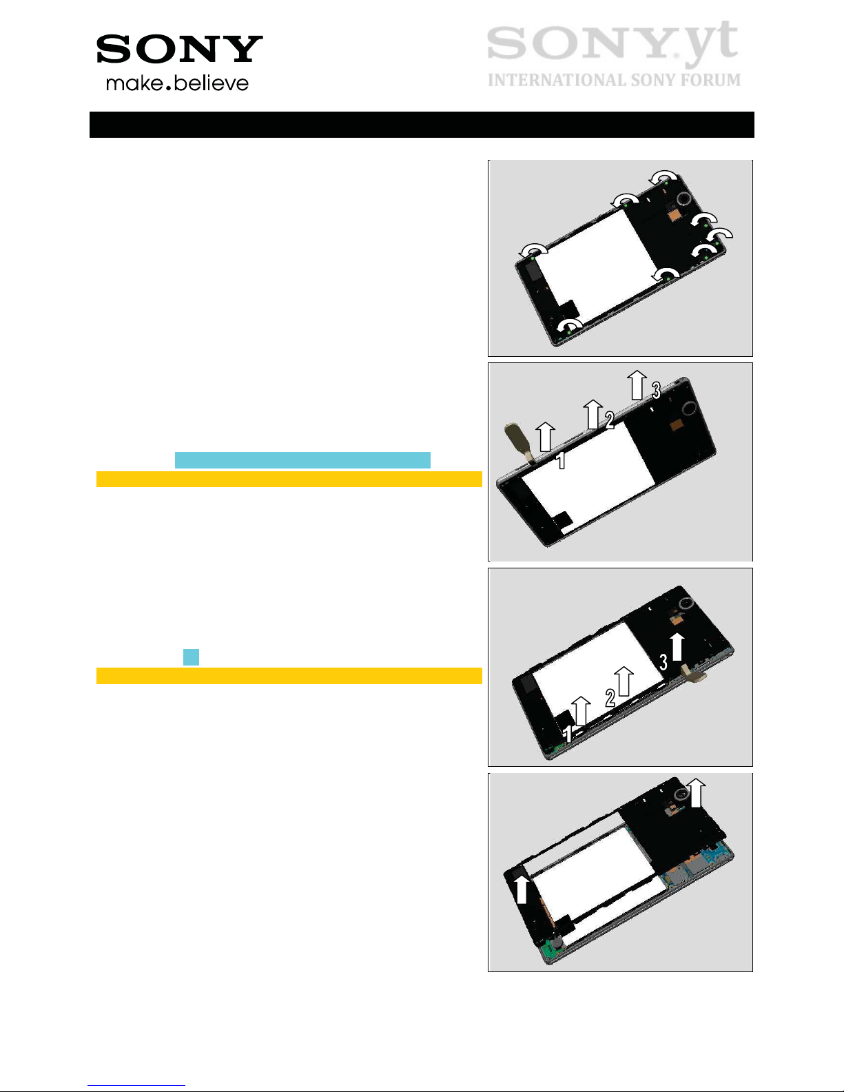
Disassembly
Remove the eight Screw Other Len:0.0 Diam:0.0 (1277-
7492) by using a screwdriver with Bits (JCIS No 0).
Insert the Front Opening Tool and pull upwards to release
the left side following the sequence shown in picture.
Do not touch the battery!
Do the same on the opposite side.
Do not touch the battery!
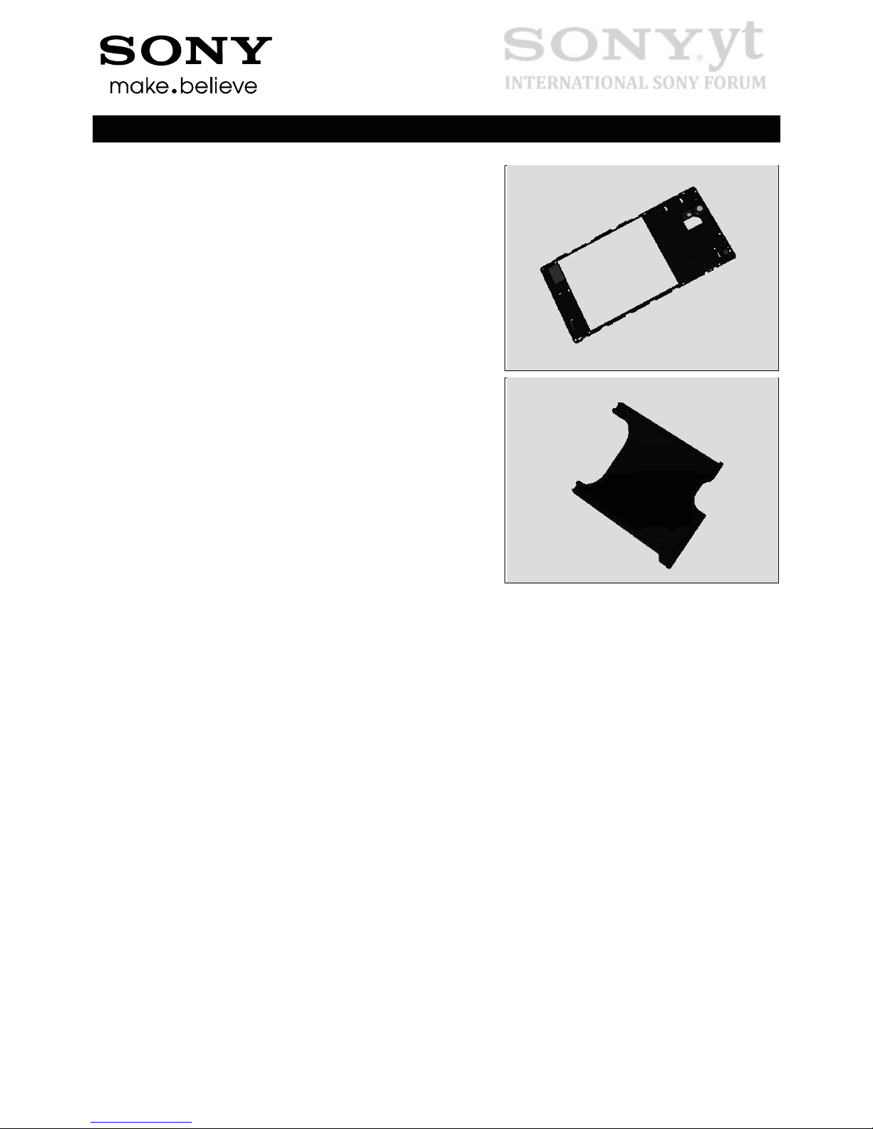
Lift gently to release the top and bottom side of Rear Cover
Assy by fingers.
Working Instructions (mech)
1282-8956 Rev 1
©
Sony Mobile Communications AB – Company Internal
9(73)
Disassembly
Remove the Rear Cover Assy.
3.4 Label Tray
Remove the Label Tray as shown.
3.5 FPC SIM (Dual & Single)
Open the Cap SIM Dual or Cap SIM Single.
(Only for D5322 and XM50h.
Skip this step for D5303, D5306, XM50t)
Detach to remove the Adhesive Battery FPC by using the
Flex Film Assembly Tool.
Working Instructions (mech)
1282-8956 Rev 1
©
Sony Mobile Communications AB – Company Internal
10(73)
Disassembly
(Only for D5322 and XM50h.
Skip this step for D5303, D5306, XM50t)
Disconnect BtB connector of Battery with the Front Opening
Tool.
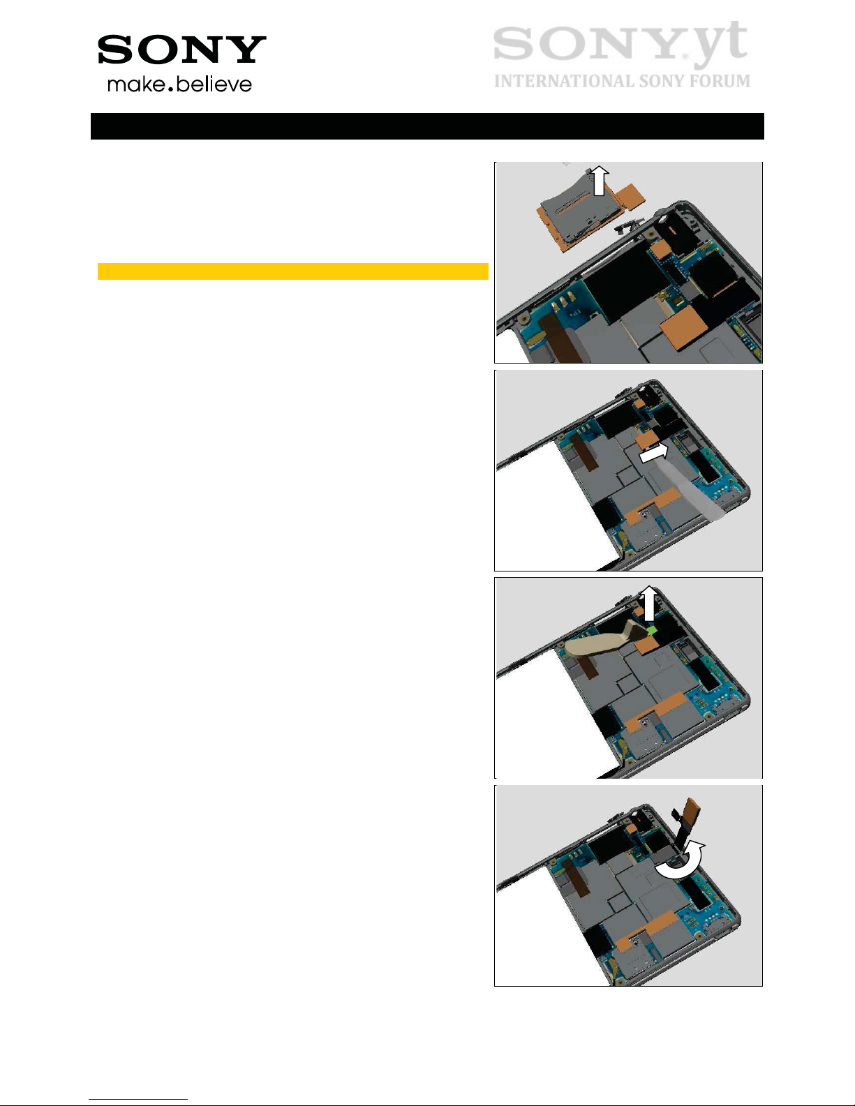
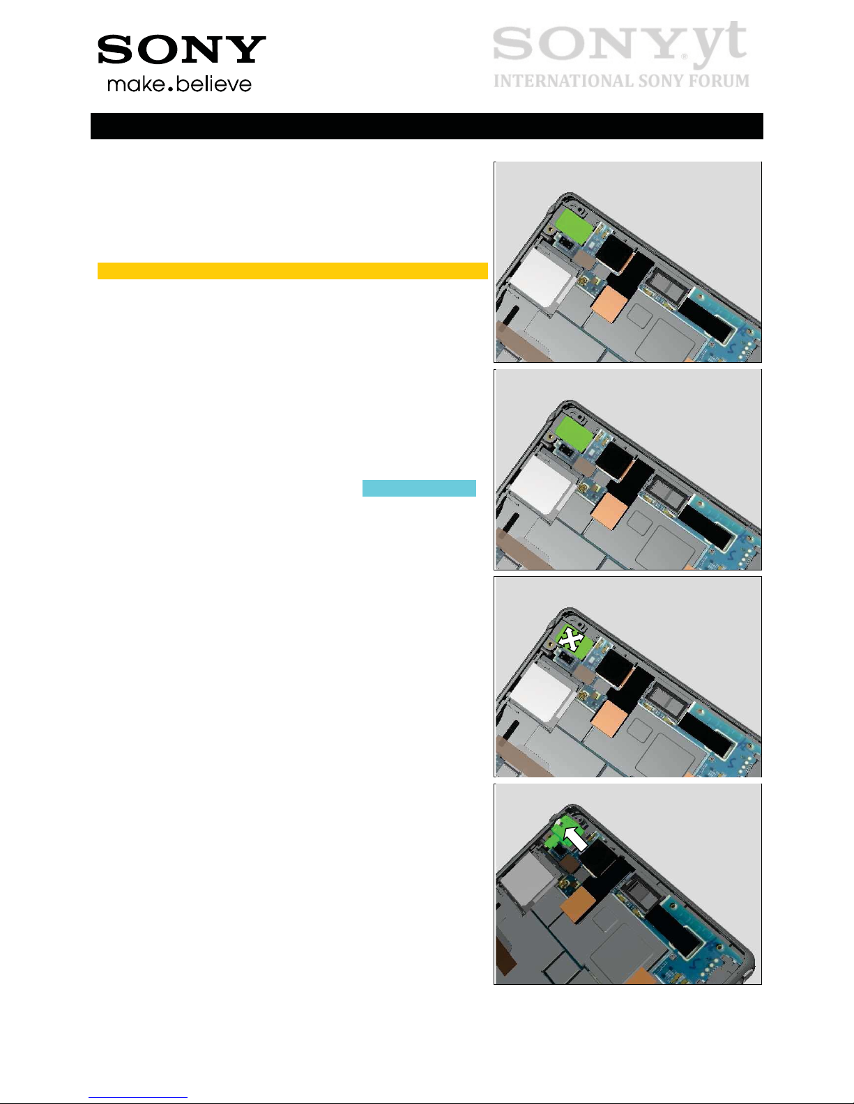
Disconnect the BtB connector of FPC SIM Single or FPC
SIM Dual.
Insert the Flex Film Assembly Tool underneath the FPC SIM
Single or FPC SIM Dual from SIM hole as shown in picture.
Slide along to detach the FPC SIM Single or FPC SIM Dual
and pull upwards to release it.
Working Instructions (mech)
1282-8956 Rev 1
©
Sony Mobile Communications AB – Company Internal
11(73)
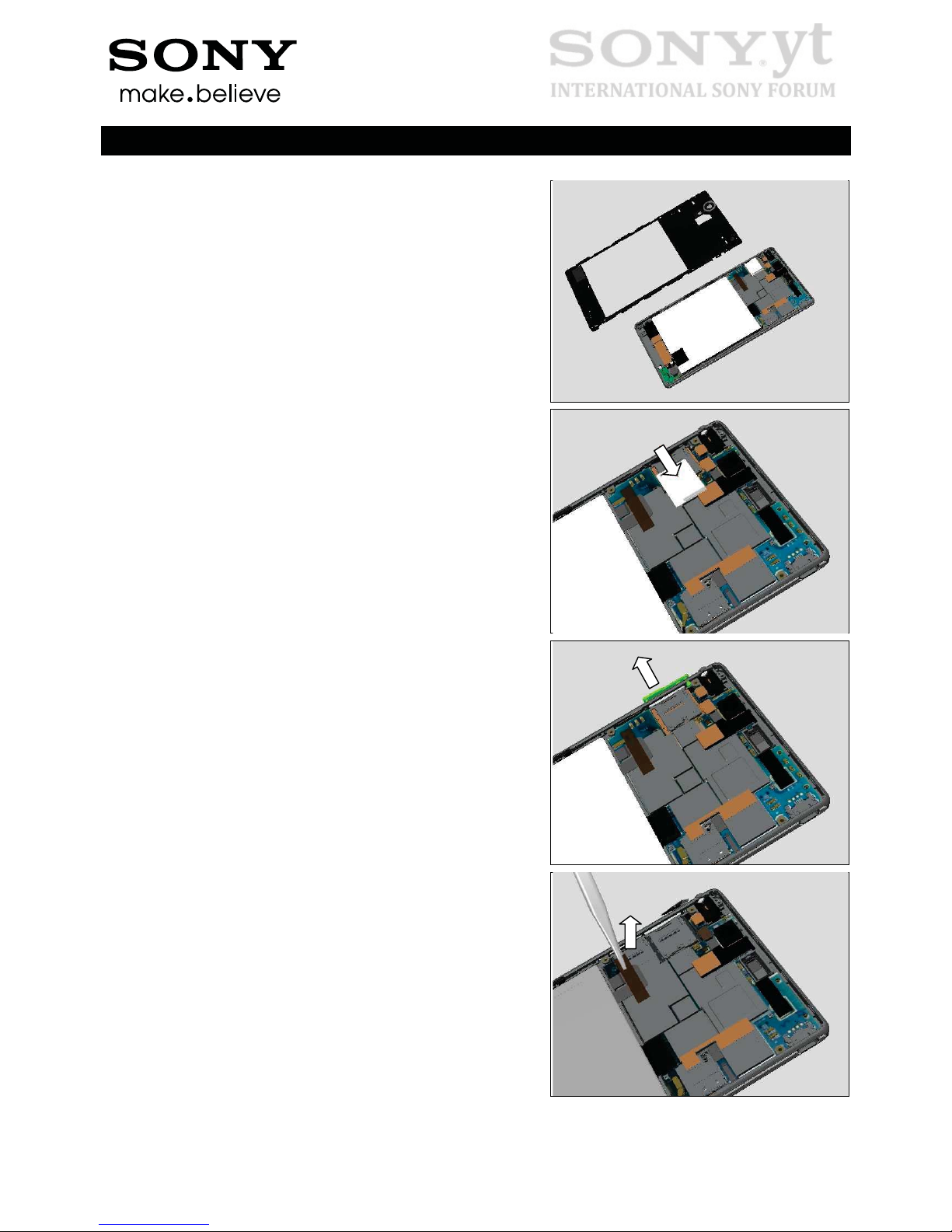
Disassembly
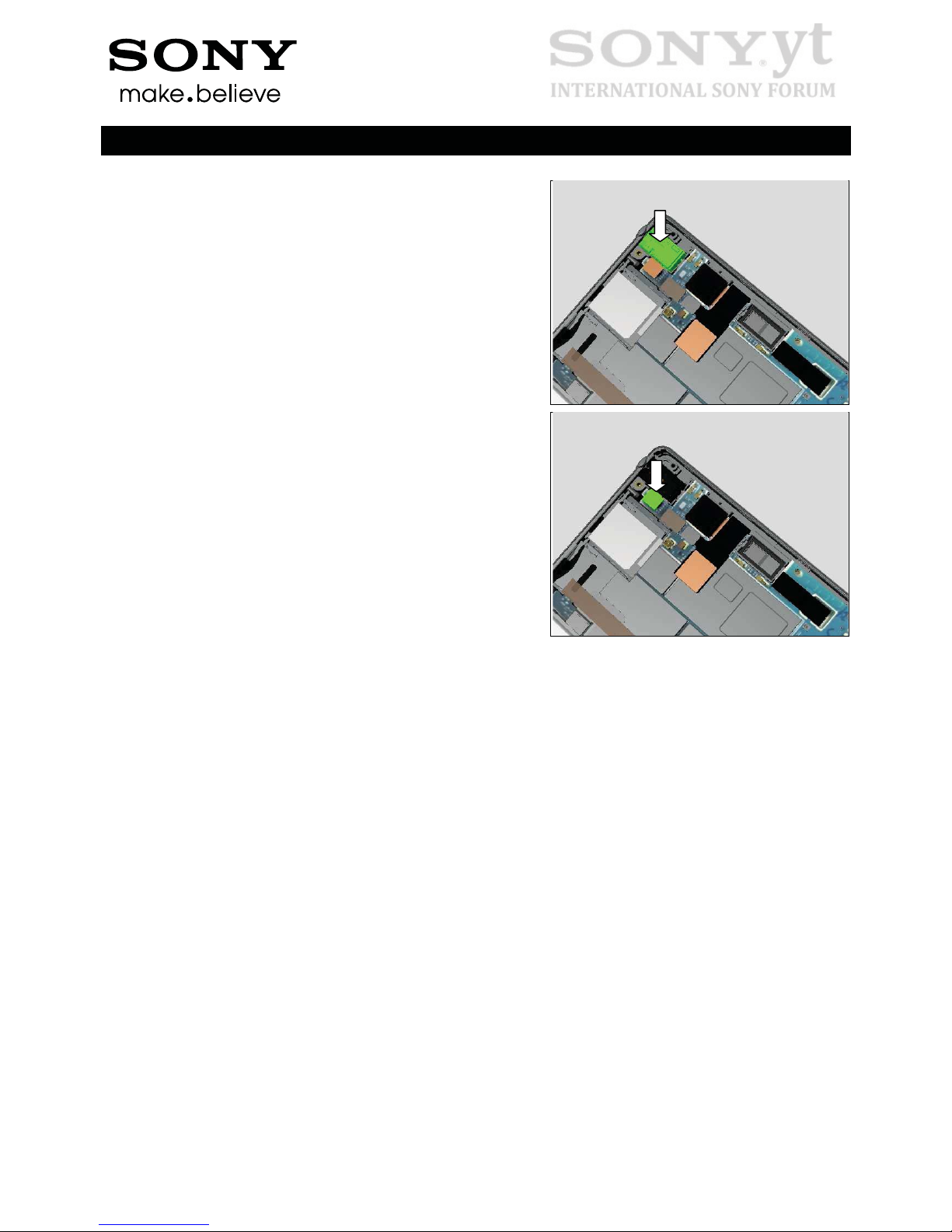
Remove FPC SIM Dual or FPC SIM Single.
Do not reuse!
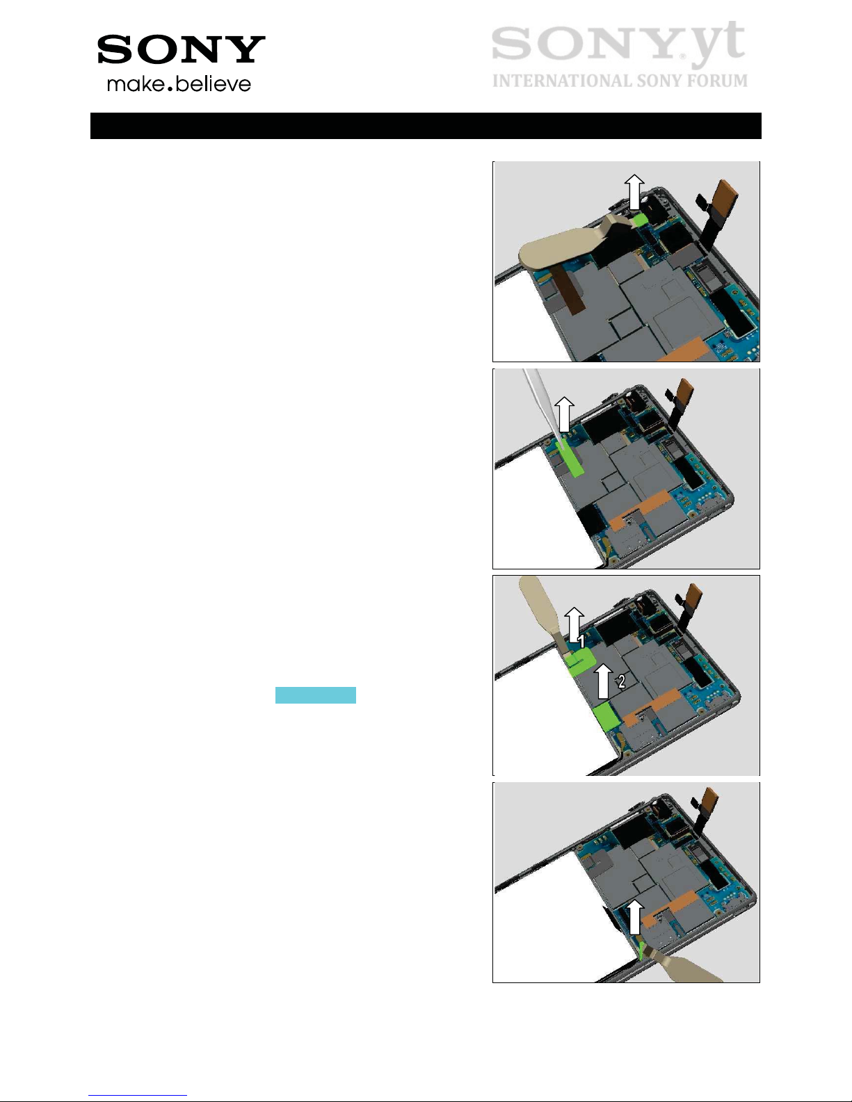
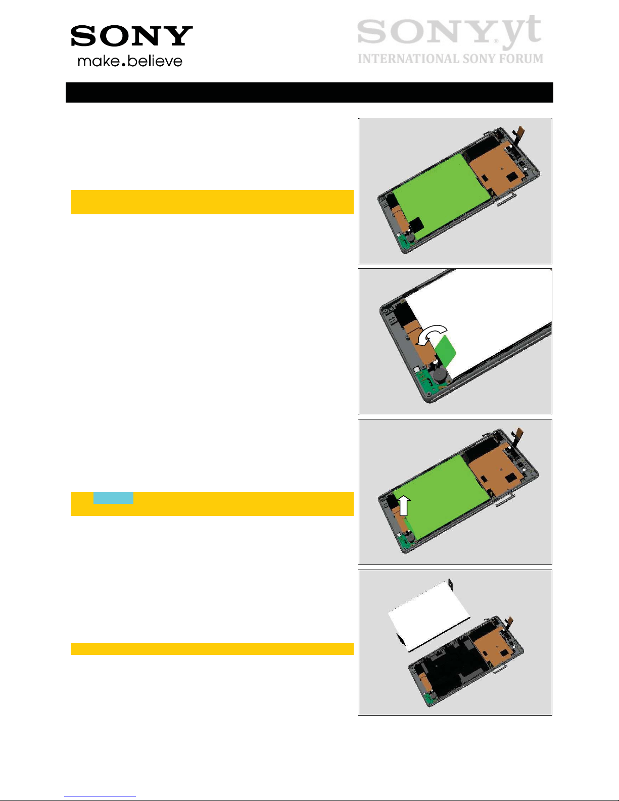
3.6 Main PBA
Insert the Flex Film Assembly Tool underneath the FPC
Touch Panel and slide to release it from adhesive as shown.
Unsnap the BtB connector with Front Opening Tool.
Turn the FPC over as shown.
Working Instructions (mech)
1282-8956 Rev 1
©
Sony Mobile Communications AB – Company Internal
12(73)
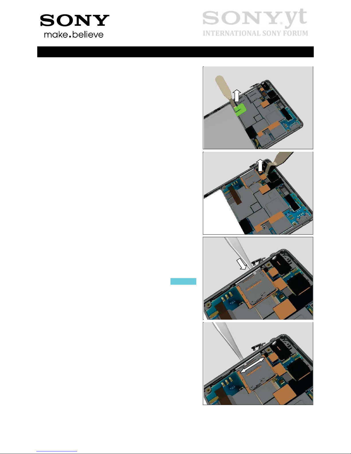
Disassembly
Disconnect BtB connector of FPC Audio Jack.
(Only for D5303, D5306, XM50t
Skip this step for D5322 and XM50h)
Detach to remove the Adhesive Battery FPC by using the
Flex Film Assembly Tool.
(Only for D5303, D5306, XM50t
Skip this step for D5322 and XM50h)
Disconnect BtB connectors following the sequence shown in
the picture.
Disconnect the coax connector by using the Front Opening
Tool.
Working Instructions (mech)
1282-8956 Rev 1
©
Sony Mobile Communications AB – Company Internal
13(73)
Disassembly
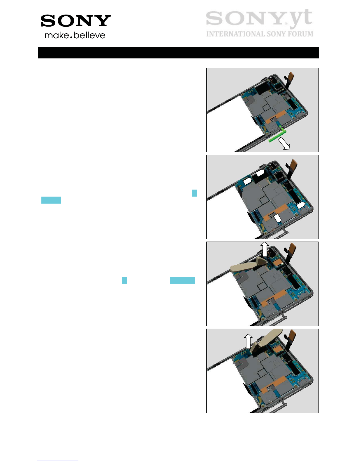
Open the Cap SD by fingers.
There are 4 snap hooks secure the Main PBA as shown in
picture.
Insert the Front Opening Tool at position shown in picture,
tilt to release the hook of Main PBA.
(Only for D5303, D5306, XM50t
Skip this step for D5322 and XM50h)
Do the same on another side as shown.
Working Instructions (mech)
1282-8956 Rev 1
©
Sony Mobile Communications AB – Company Internal
14(73)
Disassembly
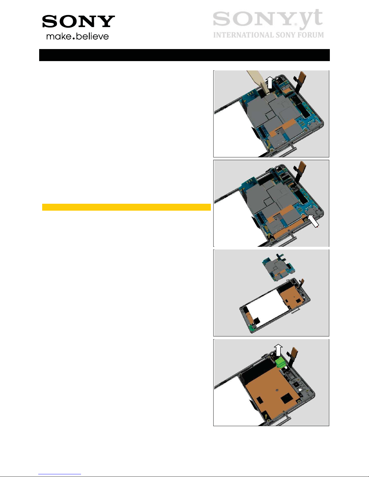
Insert the Front Opening Tool and tilt, this action will
simultaneously raise the Main PBA.
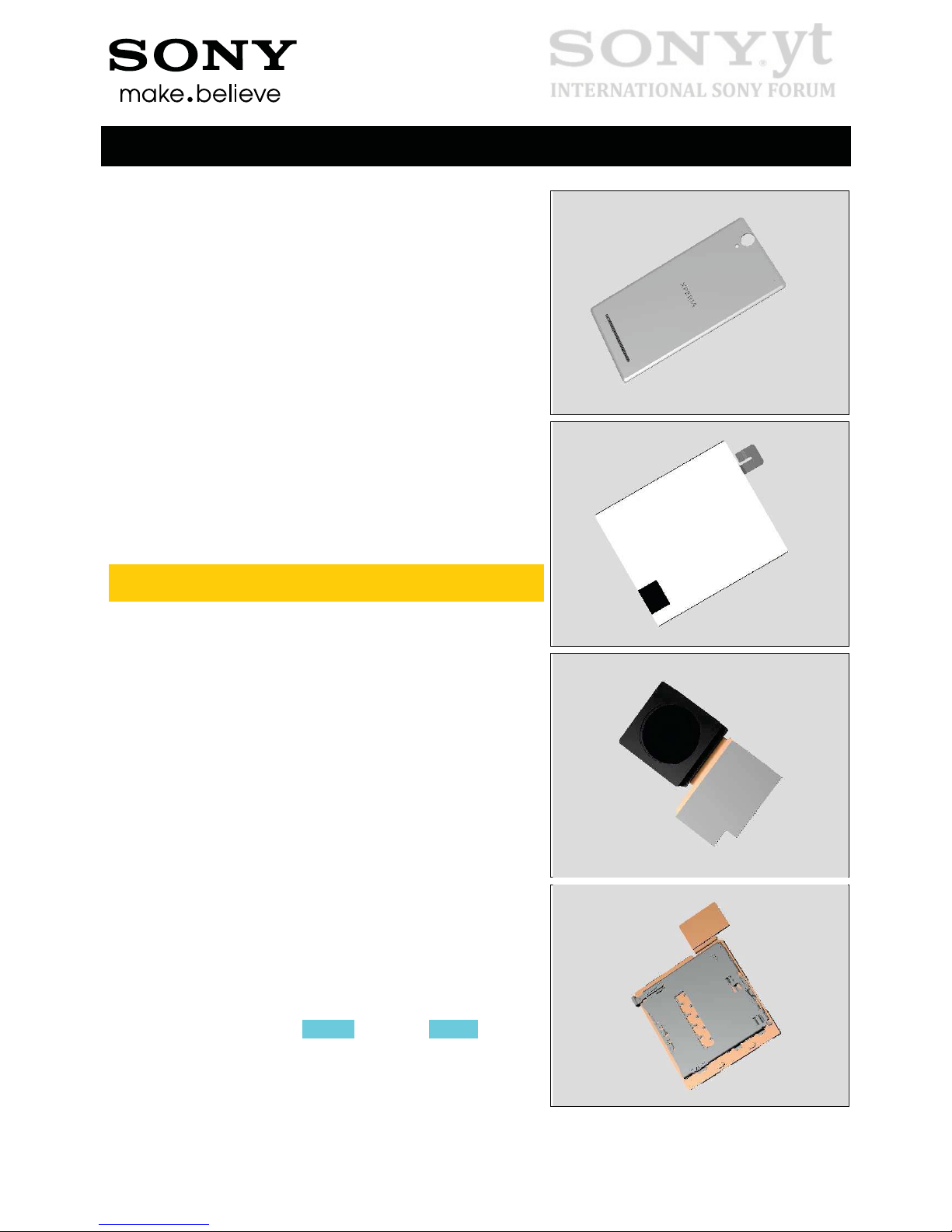
Remove the Main PBA from this side
Make Sure the USB connector is protected!
Separate the Main PBA.
Remove the Main Camera.
Working Instructions (mech)
1282-8956 Rev 1
©
Sony Mobile Communications AB – Company Internal
15(73)
Disassembly
3.7 Battery and Display Assy
Place the Front Cover Assy in a sealed ESD bag before
placing it in the freezer, set to -20C, for 30 min.
Turn the battery handle vertically.
Lift the handle to release the Battery from its adhesive
underneath.
The removal action must be done immediately after
freeze!
Separate the Battery.
Do not reuse!
Working Instructions (mech)
1282-8956 Rev 1
©
Sony Mobile Communications AB – Company Internal
16(73)
4 Replacement
4.1 Battery Cover Assy
Follow the 3.2 Disassembly instructions!
Prepare a new Battery Cover Assy.
Follow the 5.6 Reassembly instructions!
4.2 Battery
Follow the 3.1 – 3.3 & 3.7 Disassembly instructions!
Prepare the new Battery.
Follow the 5.1 & 5.5 – 5.7 Reassembly instructions!
Please refer to: Trouble Shooting Application 1257-2706
for applicable D53 calibrations!
4.3 Camera 13 MPixel CMOS
Follow the 3.1 – 3.3, 3.6 Camera Removal part of
Disassembly instructions!
Prepare the new Camera 13 MPixel CMOS.
Follow the 5.2 Camera Installation part, 5.5 – 5.7
Reassembly instructions!
4.4 FPC SIM Dual/ FPC SIM
Single
Follow the 3.1 – 3.5. Disassembly instructions!
Prepare the new FPC SIM Dual or FPC SIM Single.
Follow the 5.3 – 5.7 Reassembly instructions!
Working Instructions (mech)
1282-8956 Rev 1
©
Sony Mobile Communications AB – Company Internal
17(73)
Replacement
4.5 Rear Cover Assy
Follow the 3.1 – 3.3 Disassembly instructions!
Prepare the new Rear Cover Assy.
Follow the 5.5 – 5.7 Reassembly instructions!
4.6 SIM Tray
Follow the 3.1 Disassembly instructions!
Prepare the new SIM Tray.
Follow the 5.7 Reassembly instructions!
Working Instructions (mech)
1282-8956 Rev 1
©
Sony Mobile Communications AB – Company Internal
18(73)
Replacement
4.7 Adhesive Audio Jack & FPC Audio Jack
Follow the 3.1 – 3.3 Disassembly instructions!
Prepare the new Adhesive Audio Jack & FPC Audio Jack
Follow the 5.5 – 5.7 Reassembly instructions!
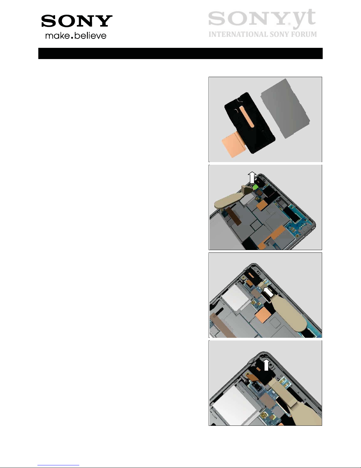
REMOVAL
Disconnect the BtB connector by using the Front Opening
Tool as shown.
Insert the Front Opening Tool underneath the FPC Audio
Jack from the angle as shown.
Pull upwards to release the FPC Audio Jack.
Working Instructions (mech)
1282-8956 Rev 1
©
Sony Mobile Communications AB – Company Internal
19(73)
Replacement: Adhesive Audio Jack & FPC Audio Jack
Remove the FPC Audio Jack.
Adhesive Audio Jack should be scrapped!
INSTALLATION
Prepare the new Adhesive Audio Jack in its proper position.
Attach the Adhesive Audio Jack into the cavity of Display
Assy and press to secure its attachment.
Insert the head of FPC Audio Jack into the Audio Jack hole.
Working Instructions (mech)
1282-8956 Rev 1
©
Sony Mobile Communications AB – Company Internal
20(73)
Replacement: Adhesive Audio Jack & FPC Audio Jack
Press to make it securely attached.
Connect the BtB connector by fingers.
Working Instructions (mech)
1282-8956 Rev 1
©
Sony Mobile Communications AB – Company Internal
21(73)
Replacement
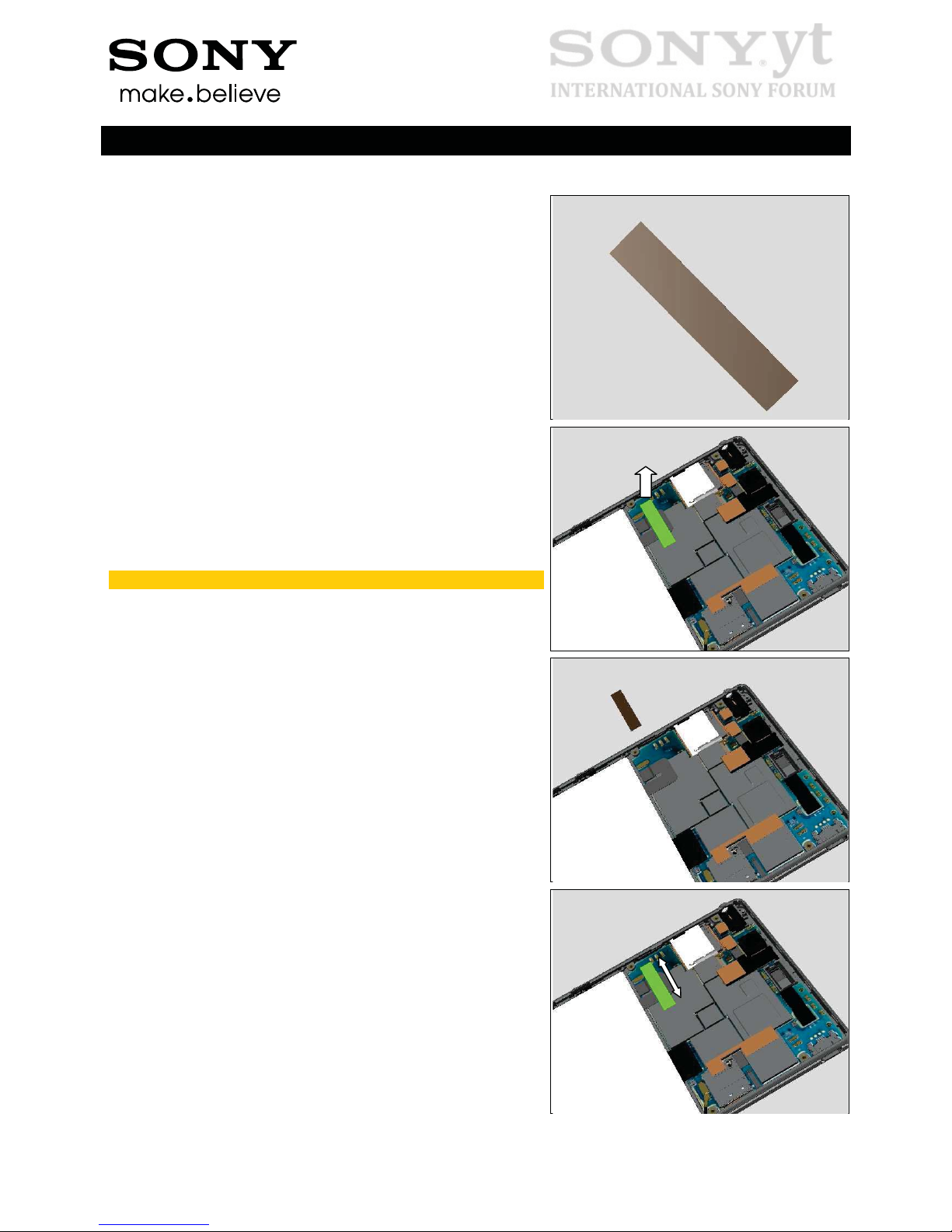
4.8 Adhesive Battery FPC
Follow the 3.1 – 3.3 Disassembly instructions!
Prepare the new Adhesive Battery FPC.
Follow the 5.5 – 5.7 Reassembly instructions!
REMOVAL
Detach to remove it gently from left side by using Flex Film
Assembly Tool.
Do not reuse!
INSTALLATION
Place a new Adhesive Battery FPC and attach it onto
Battery FPC.
Press along to make it attached firmly.
Working Instructions (mech)
1282-8956 Rev 1
©
Sony Mobile Communications AB – Company Internal
22(73)
Replacement
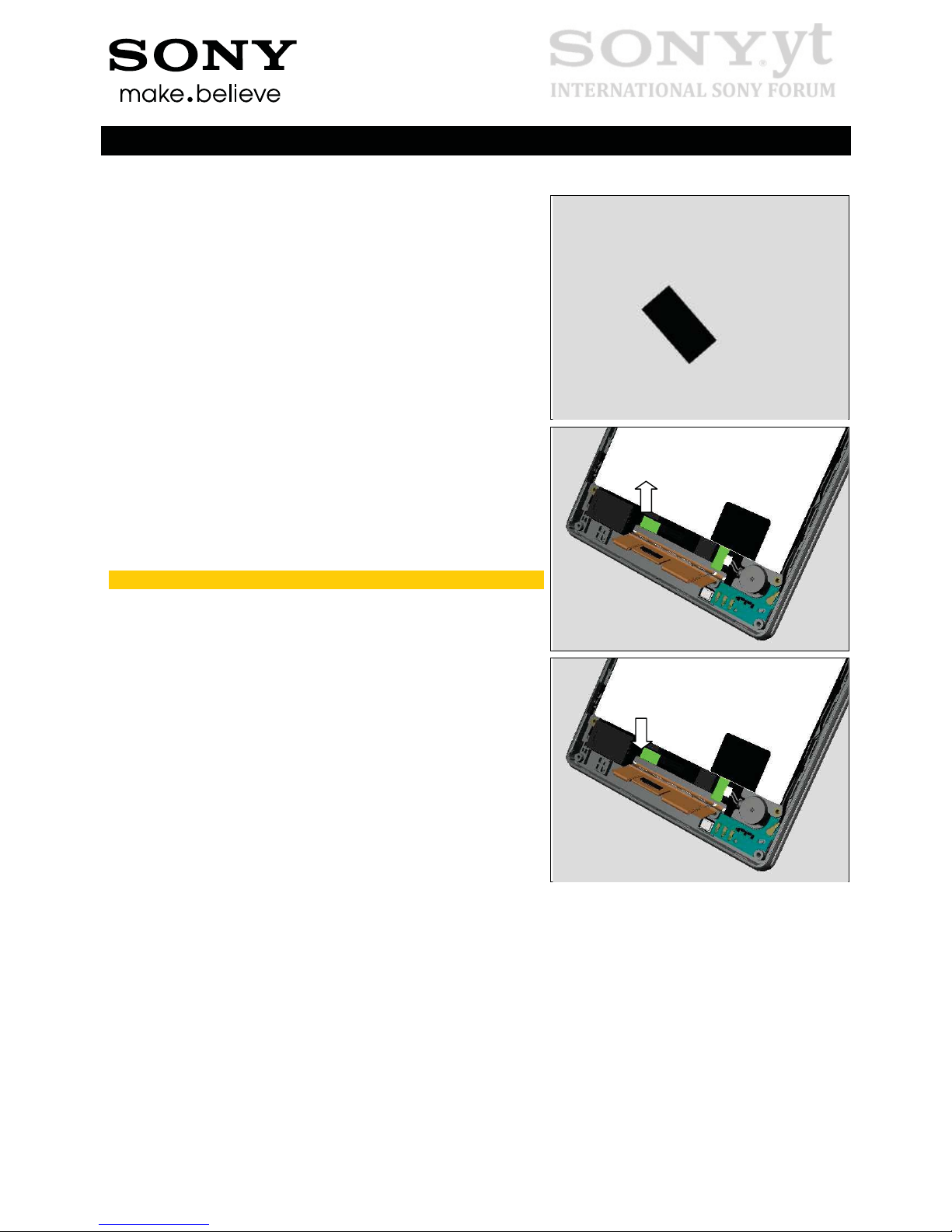
4.9 Adhesive Relay FPC Single Side
Follow the 3.1 – 3.3 Disassembly instructions!
Prepare the new Adhesive Relay FPC Single Side.
Follow the 5.5 – 5.7 Reassembly instructions!
REMOVAL
Detach to remove each of them gently by using Flex Film
Assembly Tool.
Do not reuse!
INSTALLATION
Place two pieces of new Adhesive Relay FPC Single Side
and attach them onto the Relay FPC as shown.
 Loading...