

Sony XPeria ST25i, XPeria ST25a Working Instructions
1263-4086 Rev 6
© Sony Mobile Communications AB – Company Internal
Working Instructions
- mechanical -
ST25i, ST25a

Working Instruction Repair Instruction Mechanical
1263-4086 Rev 6
© Sony Mobile Communications AB – Company Internal
2(53)
CONTENTS
1 Exterior Views ................................................................................. 4
1.1 ST25i, ST25a ......................................................................................... 4
2 Tools ................................................................................................ 5
3
Disassembly .................................................................................... 6
3.1 Battery Cover Assy & Battery ............................................................. 6
3.2
Antenna Cap ......................................................................................... 7
3.3
Carrier Frame Assy .............................................................................. 8
3.4
Carrier Window Front ass y ................................................................ 10
3.5
Main PBA & Transparent Belt Total Ass y ......................................... 12
4 Replacement ................................................................................. 14
4.1 Battery Cover Assy ............................................................................ 14
4.2
Antenna Cap ....................................................................................... 14
4.3
Carrier Frame Assy ............................................................................ 14
4.4
Transparent Belt Total Assy .............................................................. 14
4.5
Antenna Main ...................................................................................... 15
4.6
Audio Jack & Audio jack adhesive ................................................... 17
4.7
Audio Jack Sensor FPC Assy ........................................................... 19
4.8
Core Unit Label ................................................................................... 20
4.9
Touch Panel Glass Window 3.5 with G a s ke t .................................... 22
4.10
Display ................................................................................................ 26
4.11
Carrier Window Front assy ................................................................ 29
4.12
Ear Speaker & Receiver adhesive ..................................................... 30
4.13
Loudspeaker & Speaker adhesive .................................................... 32
4.14
kMain Ca mera ..................................................................................... 34
4.15
Main Camera Copper & Main Camera Film ....................................... 36
4.16
Shield Can Lid ABB ............................................................................ 38
4.17
Shield Can Lid BT GPS ...................................................................... 39
4.18
Shield Can Lid DBB ............................................................................ 40
4.19
Sub Camera Rubber ........................................................................... 41
4.20
Water indicator ................................................................................... 42
4.21
Board Swap - Replacement ............................................................... 44
4.22
Board Swap – Change Label ............................................................. 44
4.23
Board Swap – Customize of Software .............................................. 44
5 Reassembly ................................................................................... 45
5.1 Main PBA & Transparent Belt Total Assy ......................................... 45
5.2
Carrier Window Front ass y ................................................................ 46
5.3
Carrier Frame Assy ............................................................................ 47
5.4
Antenna Cap ....................................................................................... 49
5.5
Battery Cover Assy & Battery ........................................................... 50

Working Instruction Repair Instruction Mechanical
1263-4086 Rev 6
© Sony Mobile Communications AB – Company Internal
3(53)
6 Country of Origin Barcodes for Brazil/VIVO Labels .................. 52
7
Revision History ........................................................................... 53
For general information about mechanical repair related issues, refer to
1220-1333: Generic Repair Manual - mechanical
Working Instruction Repair Instruction Mechanical
1263-4086 Rev 6
© Sony Mobile Communications AB – Company Internal
4(53)
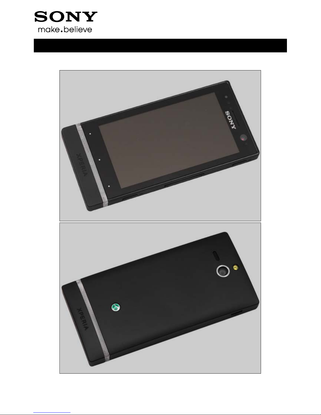
1 Exterior Views
1.1 ST25i, ST25a
Working Instruction Repair Instruction Mechanical
1263-4086 Rev 6
© Sony Mobile Communications AB – Company Internal
5(53)
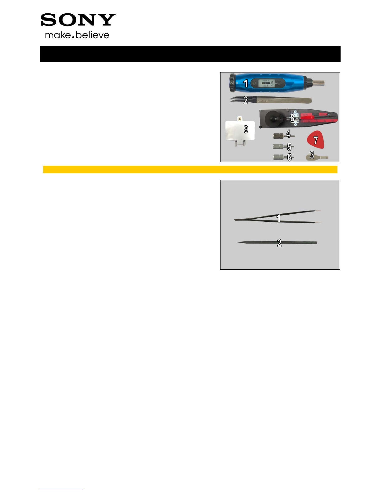
2 Tools
SPECIAL TOOLS
1. Torque Screwdriver
2. Flex Film Assembly Tool
3. Front Opening Tool
4. Bits(JCIS No 0)
5. Bits(T5)
6. Bits(T6)
7. Guitar Pick
8. Pressure Tool
9. Pressure Fixture
For part no’s on the tools above, refer to the ‘Tools Catalogue/Matrix’!
STANDARD T OOLS
1. Tweezers (ESD-safe & non-metallic)
2. Nylon Pointer
Working Instruction Repair Instruction Mechanical
1263-4086 Rev 6
© Sony Mobile Communications AB – Company Internal
6(53)
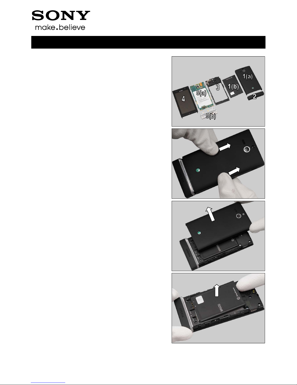
3 Disassembly
The disassembly is done in the following order:
1. Batt ery Cover Assy (a) & Battery (b)
2. Antenna Cap
3. Carrier Frame Assy
4. Carrier Window Front assy
5. Main PBA (a) & Transparent Belt Total Assy (b)
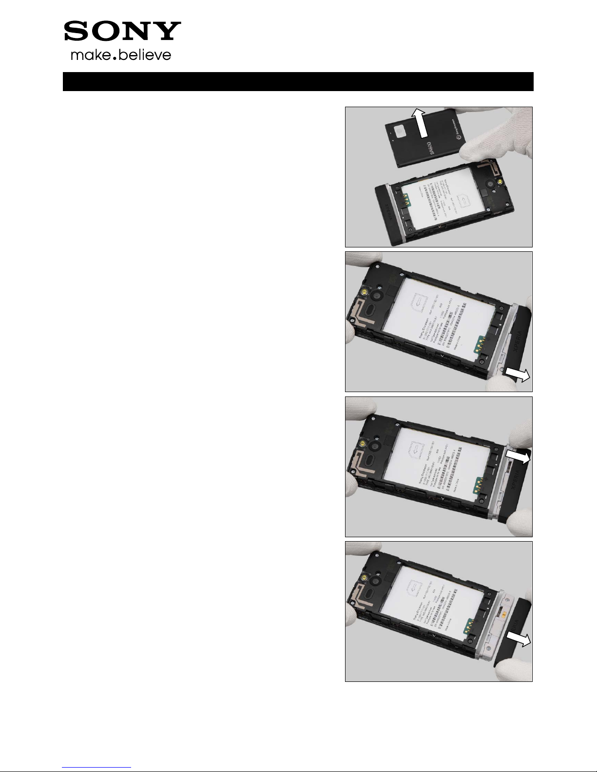
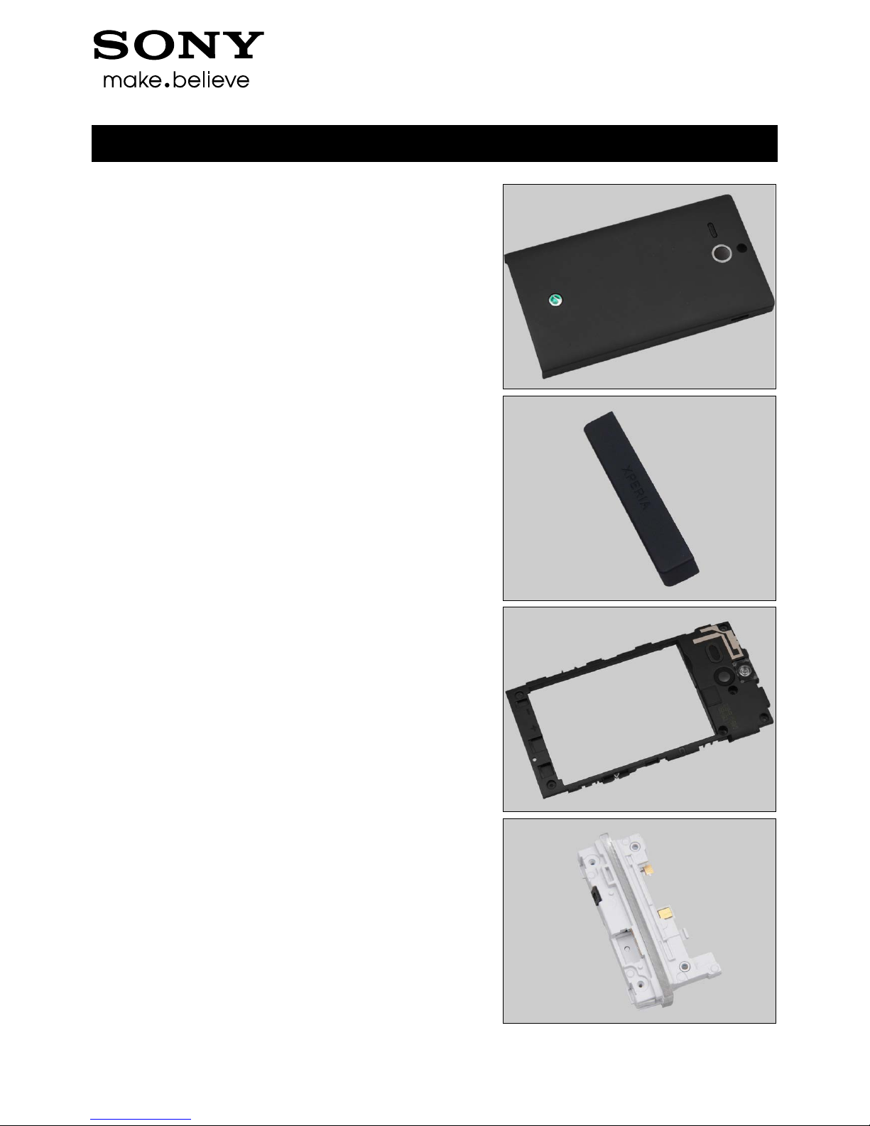
3.1 Bat tery Cover Assy &
Battery
Push upwards the Battery Cover Assy with fingers.
Remove the Battery Cover Assy.
Lift up the battery from its cavity.
Working Instruction Repair Instruction Mechanical
1263-4086 Rev 6
© Sony Mobile Communications AB – Company Internal
7(53)
Disassembly
Remove the battery.
3.2 Ant enna Cap
Release the hook of Antenna Cap from the gap between
Antenna Cap and Transparent Belt Total Assy from left side
with fingers.
Release the hook from right side.
Remove the Antenna Cap.
Working Instruction Repair Instruction Mechanical
1263-4086 Rev 6
© Sony Mobile Communications AB – Company Internal
8(53)
Disassembly
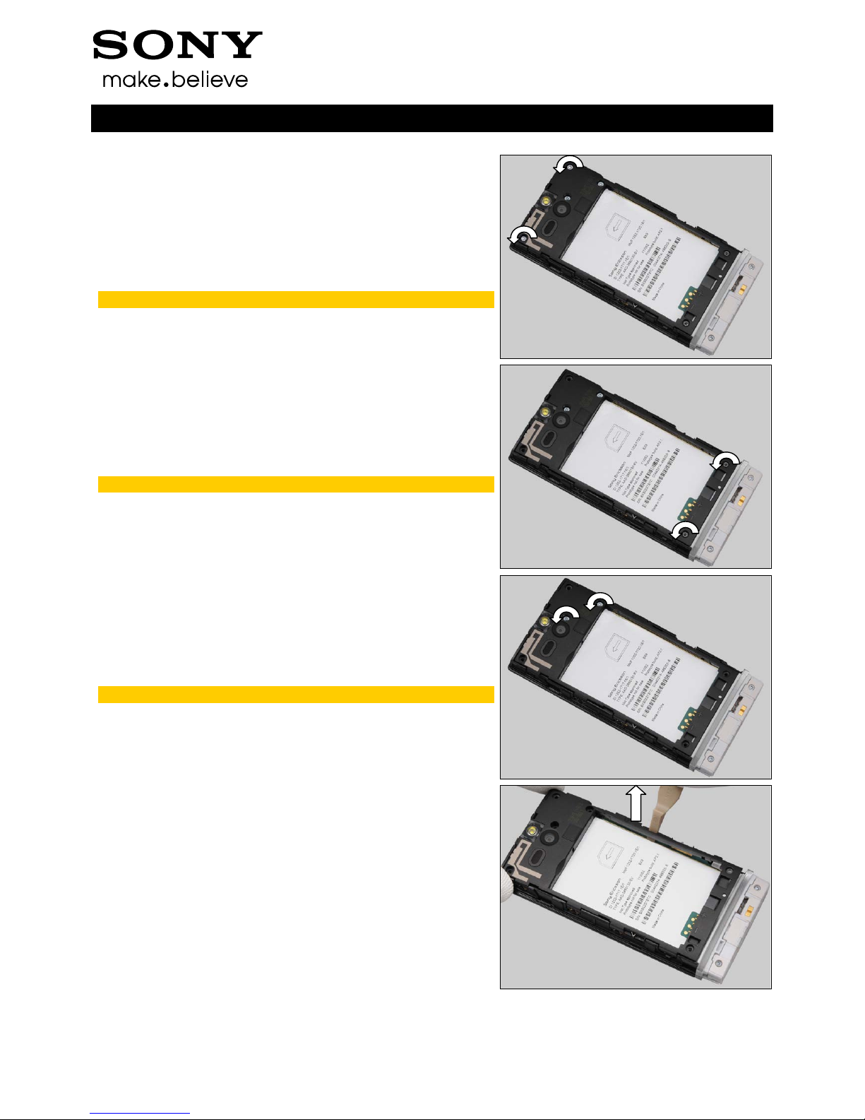
3.3 Carr ier Frame Assy
Remove the Screw Other Len:4.0 Diam:1.4 by a screwdriver
with Bits (T5).
Scrap! Not to be reused!
Remove the Screw Torx Len:5.4 Diam:2.5 by using a
screwdriver with Bits (T6).
Scrap! Not to be reused!
Remove the Screw Torx Len:3.4 Diam:3.0 by using a
screwdriver with Bits (T5).
Scrap! Not to be reused!
Insert the Front Opening Tool to release the hook in the
middle of right side on Carrier Frame Assy.
Working Instruction Repair Instruction Mechanical
1263-4086 Rev 6
© Sony Mobile Communications AB – Company Internal
9(53)
Disassembly
Insert the Front Opening Tool to release the hook at top of
right side on Carrier Frame Assy.
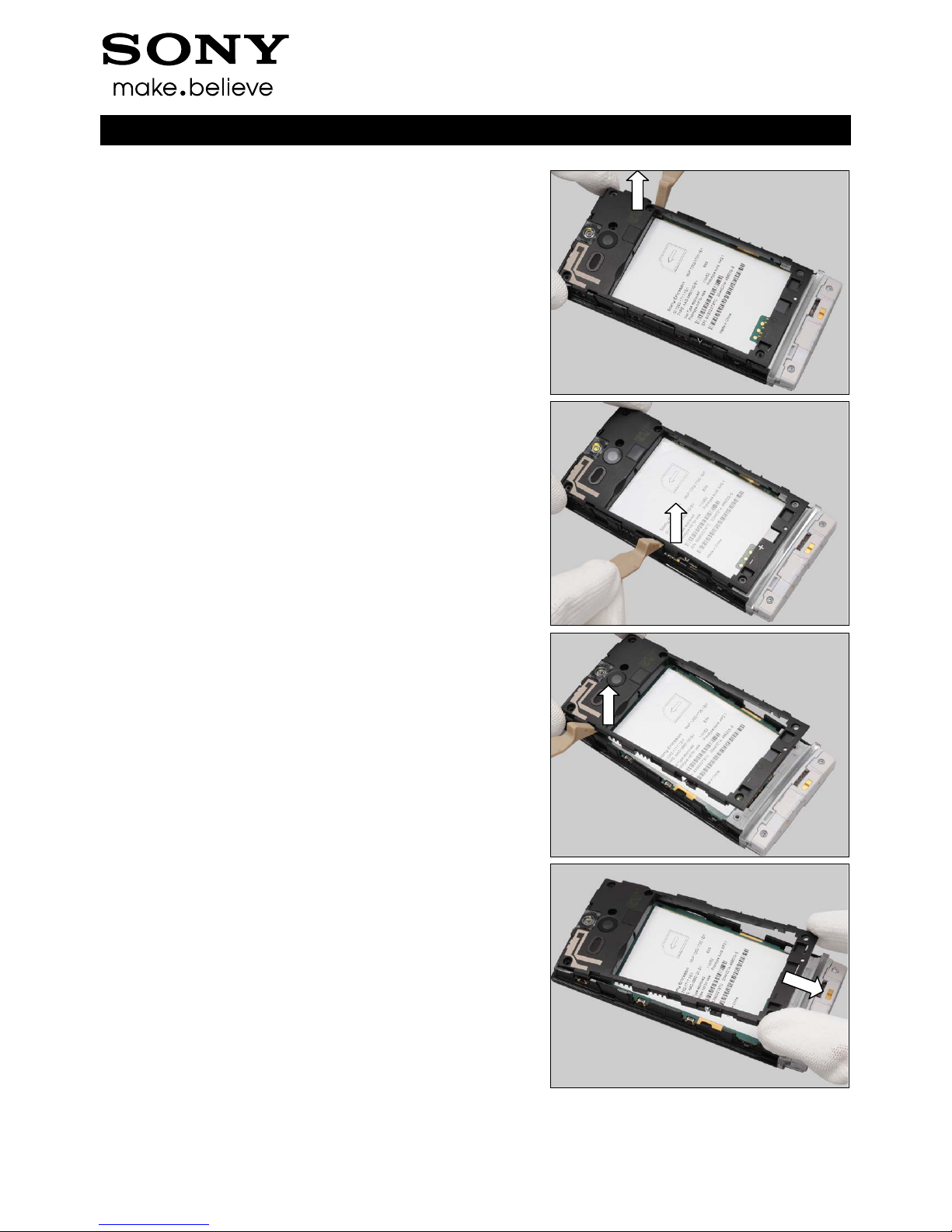
Insert the Front Opening Tool to release the hook in the
middle of left side on Carrier Frame Assy.
Insert the Front Opening Tool to release the hook at top of
left side on Carrier Frame Assy.
Remove the Carrier Frame Assy.
Working Instruction Repair Instruction Mechanical
1263-4086 Rev 6
© Sony Mobile Communications AB – Company Internal
10(53)
Disassembly
3.4 Carrier W ind ow Front
assy
There are three hooks to secure the Main PBA as shown in
the picture.
Push the Carrier Window Front assy with your thumb to
release the hook in the middle of right side and turn upwards
the Transparent Belt Total Assy.
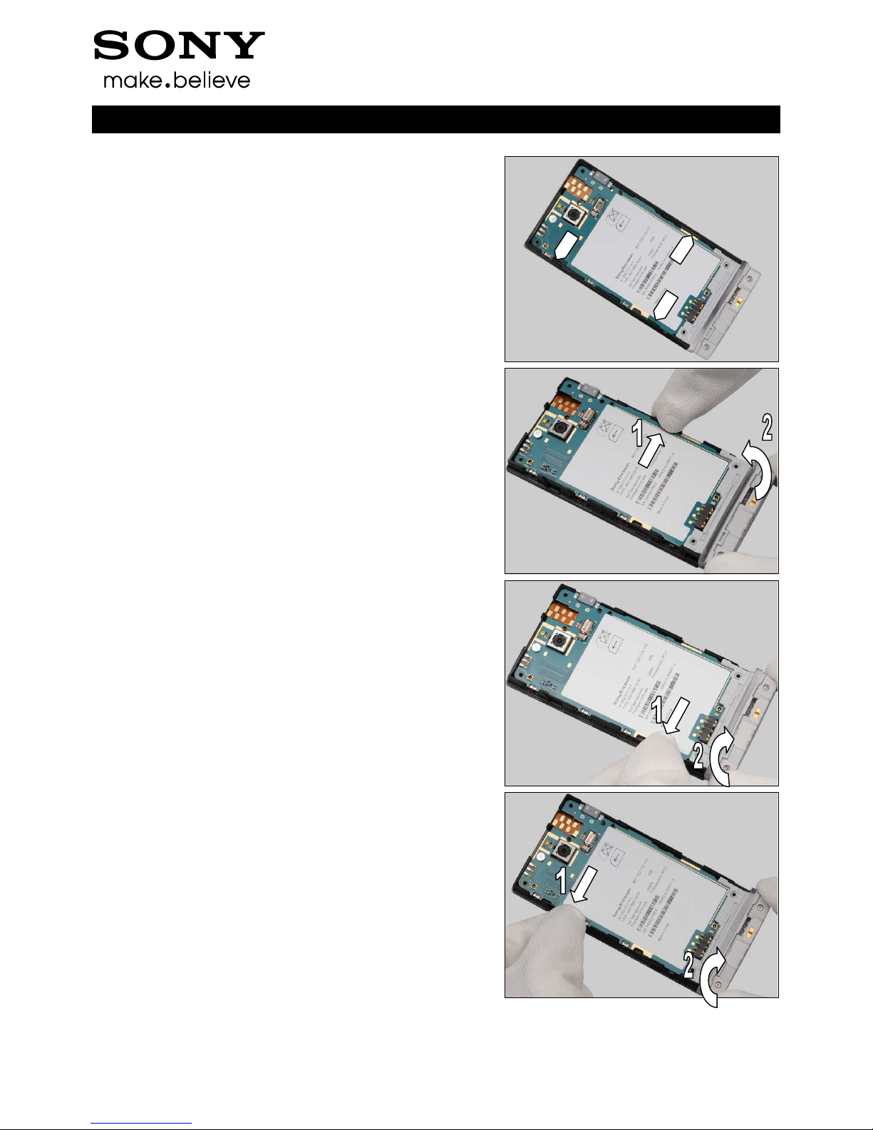
Push the Carrier Window Front assy with your thumb to
release the hook at bottom of left side and turn upwards the
Transparent Belt Total Assy.
Push the Carrier Window Front assy with your thumb to
release the hook at top of left side and turn upwards the
Transparent Belt Total Assy.
Working Instruction Repair Instruction Mechanical
1263-4086 Rev 6
© Sony Mobile Communications AB – Company Internal
11(53)
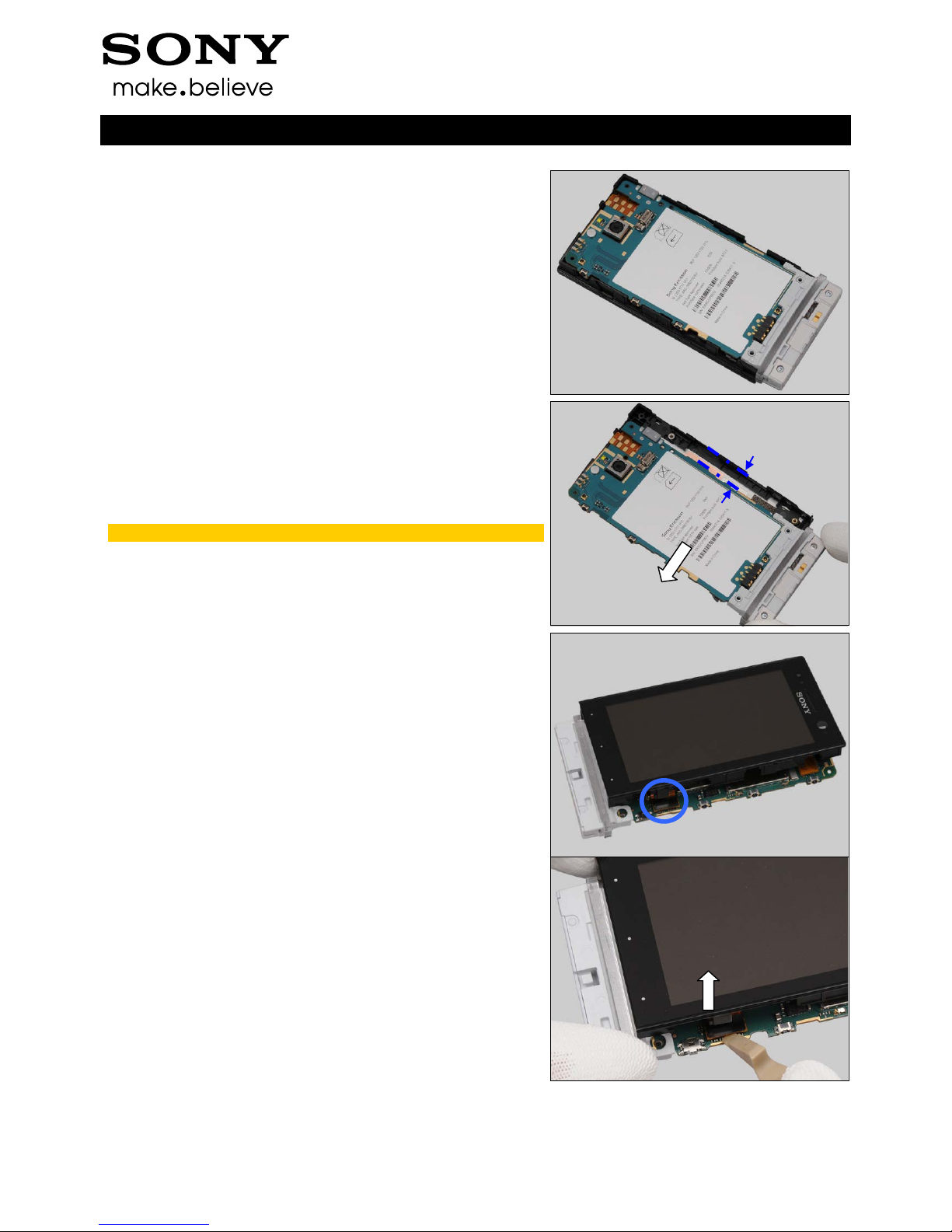
Disassembly
The three hooks have all been released as shown in the
picture.
Move the Main PBA 5mm away from the Carrier Window
Front assy.
Do not stretch the FPC of BtB connector!
Turn over the phone to show the BtB connector.
Unsnap the BtB connector by using a Front Opening Tool.
5mm
Working Instruction Repair Instruction Mechanical
1263-4086 Rev 6
© Sony Mobile Communications AB – Company Internal
12(53)
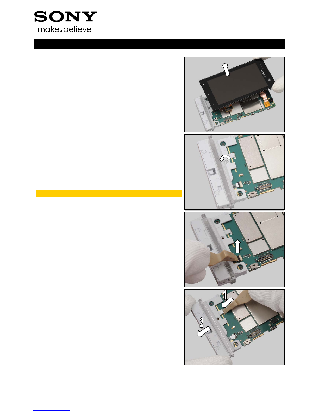
Disassembly
Remove the Carrier Window Front assy.
3.5 M ain PBA & Transparen t
Belt Total Assy
Remove the Screw Torx Len:3.1 Diam:1.4 by using a
screwdriver with Bits (JCIS No 0).
Scrap! Not to be reused!
Unlock the ZIF connector by using a Front Opening Tool.
Insert Front Opening Tool to release the hook and pull out
the Transparent Belt Total Assy.
Working Instruction Repair Instruction Mechanical
1263-4086 Rev 6
© Sony Mobile Communications AB – Company Internal
13(53)
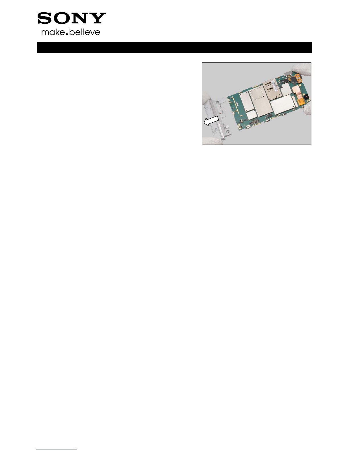
Disassembly
Separate the Main PBA from Transparent Belt Total Assy
carefully.
Working Instruction Repair Instruction Mechanical
1263-4086 Rev 6
© Sony Mobile Communications AB – Company Internal
14(53)
4 Replacement
4.1 Bat tery Cover Assy
Follow the 3.1 Disassembly instructions!
Prepare the new Battery Cover Assy.
Follow the 5.5 Reassembly instructions!
4.2 Ant enna Cap
Follow the 3.1 – 3.2 Disassembly instructions!
Prepare the new Antenna Cap.
Follow the 5.4 – 5.5 Reassembly instructions!
4.3 Carr ier Frame Assy
Follow the 3.1 – 3.3 Disassembly instructions!
Follow the 4.6, 4.13, 4.20 Removal instructions!
Prepare the new Carrier Frame Assy.
Follow the 4.6, 4.13, 4.20 Installation instructions!
Follow the 5.3 – 5.5 Reassembly instructions!
4.4 Transparent Belt Total
Assy
Follow the 3.1 – 3.5 Disassembly instructions!
Follow the 4.5 Removal instructions!
Prepare the new Transparent Belt Total Assy.
Follow the 4.5 Installation instructions!
Follow the 5.1 – 5.5 Reassembly instructions!
Working Instruction Repair Instruction Mechanical
1263-4086 Rev 6
© Sony Mobile Communications AB – Company Internal
15(53)
Replacement
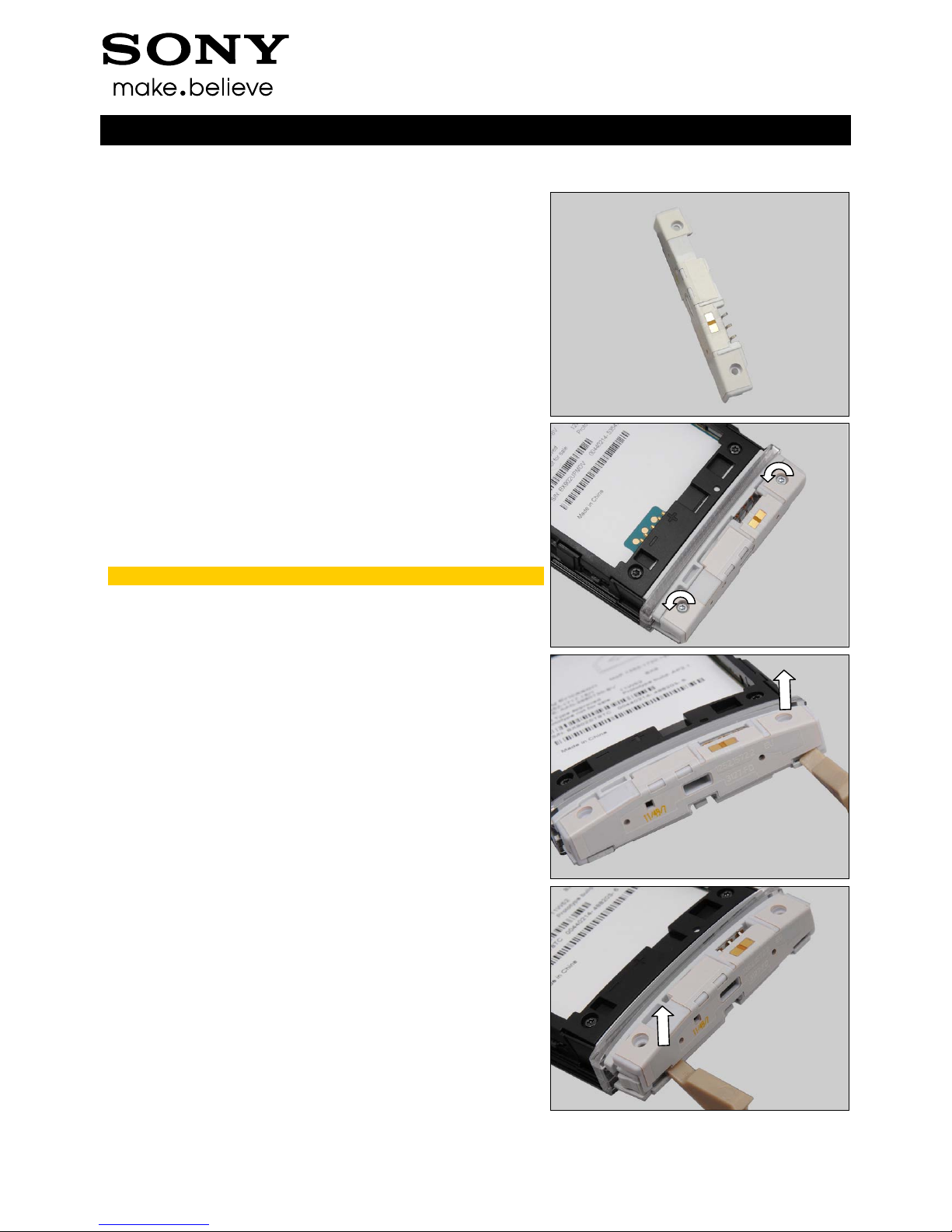
4.5 Ant enna Main
Follow the 3.1 – 3.2 Disassembly instructions!
Carry out the Removal as described below.
Prepare the new Antenna Main.
Carry out the Installation as described below.
Follow the 5.4 – 5.5 Reassembly instructions!
REMOVAL
Remove the Screw Other Len:4.0 Diam:1.4 by using a
screwdriver with T5
.
Scrap! Not to be reused!
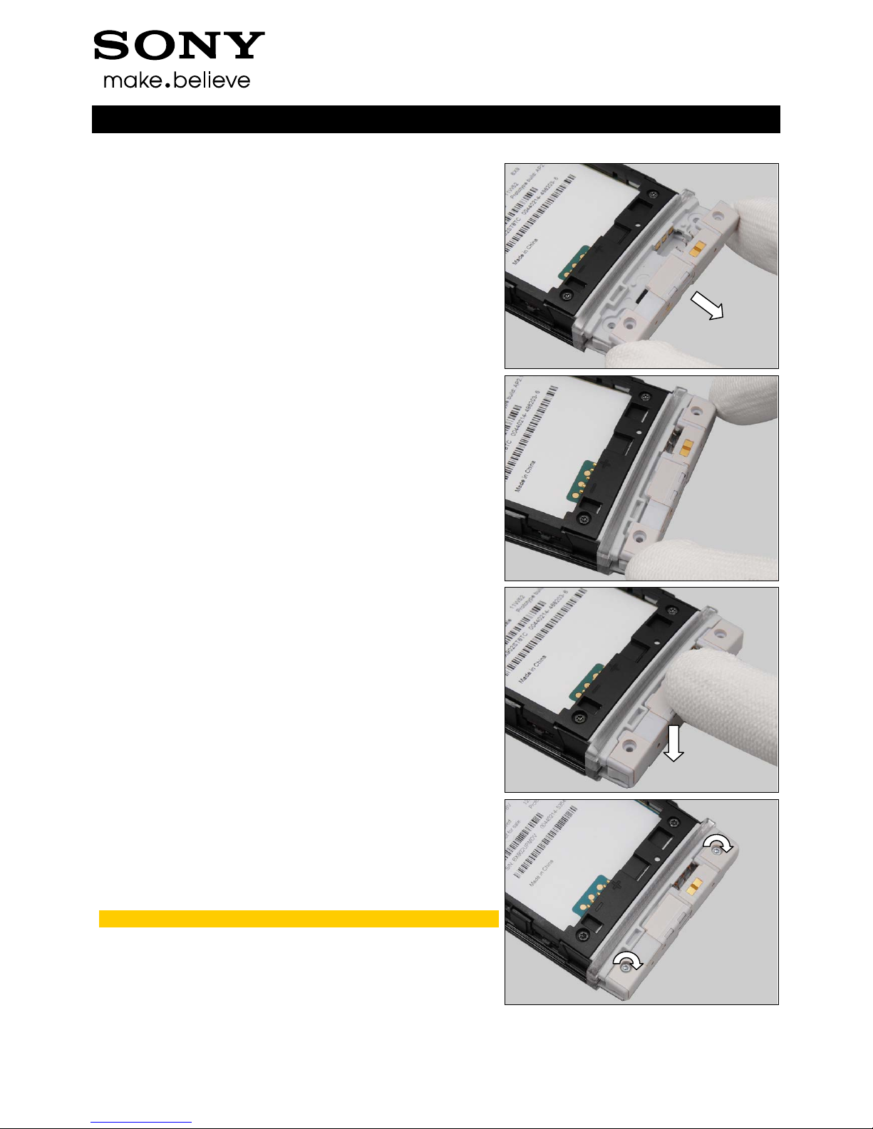
Detach the Antenna Main from right bottom side by using a
Front Opening Tool.
Detach the Antenna Main from left bottom side by using a
Front Opening Tool.
Working Instruction Repair Instruction Mechanical
1263-4086 Rev 6
© Sony Mobile Communications AB – Company Internal
16(53)
Replacement: Antenna Main
Remove the Antenna Main.
INSTALLATION
Place a new Antenna Main in the correct position.
Press to secure its position.
Apply 6 ± 1 Ncm torque when tightening the Screw Other
Len:4.0 Diam:1.4 with T5.
Take new screws!
 Loading...