

Sony Xperia S LT26i Service manual
1257-2928 Rev 2
Sony Mobile Communications AB – Company Internal
Working Instructions
- mechanical -
Xperia S
LT26i, SO-02D

1257-2928 Rev 2
Sony Mobile Communications AB – Company Internal
2(90)
Working Instruction Repair Instruction Mechanical/
CONTENTS
1 Exterior Views ................................................................................. 4
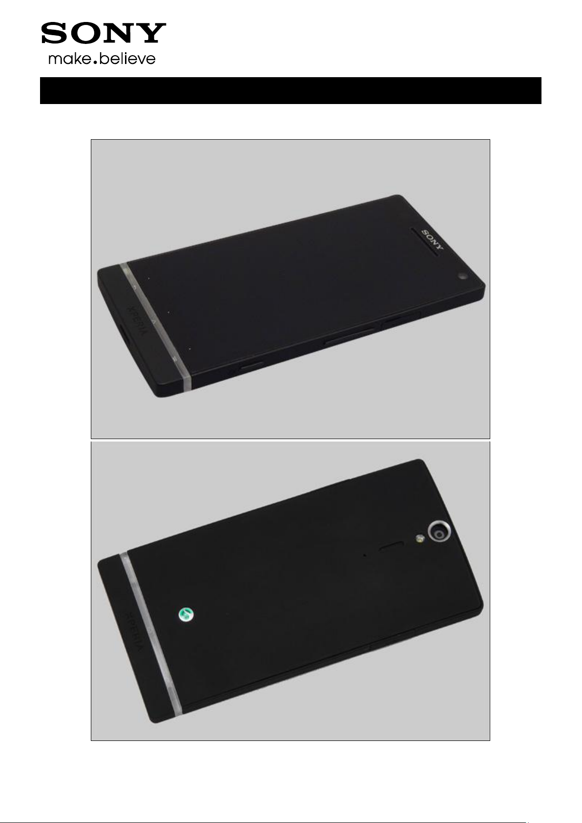
1.1 LT26i ..................................................................................................... 4
2 Tools ................................................................................................ 5
3 Disassembly.................................................................................... 6
3.1 Cover Rear Assy .................................................................................. 6
3.2 Cover Bottom ....................................................................................... 6
3.3 Battery ................................................................................................... 7
3.4 Rear Frame Assy .................................................................................. 8
3.5 Main Camera ......................................................................................... 9
3.6 Main PBA .............................................................................................. 9
3.7 Cover Transparent Assy & Cover Front Assy .................................. 11
4 Replacement ................................................................................. 13
4.1 Cover Rear Assy ................................................................................ 13
4.2 Cover Bottom ..................................................................................... 13
4.3 Battery ................................................................................................. 13
4.4 Rear Frame Assy ................................................................................ 13
4.5 Main Camera ....................................................................................... 14
4.6 Cover Front Assy ............................................................................... 14
4.7 Cover Transparent Assy .................................................................... 14
4.8 Ant GPS .............................................................................................. 15
4.9 Audio Jack .......................................................................................... 17
4.10 Cap HDMI ............................................................................................ 19
4.11 Cap RF ................................................................................................ 20
4.12 Cap USB .............................................................................................. 21
4.13 Carrier Holder Bottom ........................................................................ 23
4.14 Carrier Holder Proximity Sensor ....................................................... 24
4.15 Carrier Vibrator ................................................................................... 25
4.16 Core Unit Label ................................................................................... 26
4.17 Cushion Camera 1 .............................................................................. 28
4.18 Cushion Receiver ............................................................................... 29
4.19 Cushion Speaker ................................................................................ 31
4.20 Cushion Sub PBA .............................................................................. 33
4.21 Cushion Vib ........................................................................................ 35
4.22 Ear Speaker ........................................................................................ 36
4.23 Foil Adhesive Audio Jack .................................................................. 38
4.24 Foil Adhesive GPS Ant ...................................................................... 40
4.25 Foil Adhesive NFC PBA ..................................................................... 42
4.26 Foil Adhesive Speaker ....................................................................... 44
4.27 Foil Adhesive Transparent Front ...................................................... 46

1257-2928 Rev 2
Sony Mobile Communications AB – Company Internal
3(90)
Working Instruction Repair Instruction Mechanical/
4.28 FPC Jack Assy ................................................................................... 48
4.29 FPC Main Assy ................................................................................... 50
4.30 Key Camera ........................................................................................ 54
4.31 Key On/Off .......................................................................................... 55
4.32 Key Volume ........................................................................................ 56
4.33 Loudspeaker ....................................................................................... 57
4.34 Main Antenna ...................................................................................... 59
4.35 NFC Antenna ...................................................................................... 61
4.36 PBA Bottom ........................................................................................ 62
4.37 PBA NFC ............................................................................................. 63
4.38 RF Cable ............................................................................................. 65
4.39 Sheet GPS Ant .................................................................................... 66
4.40 Sheet LCD FPC ................................................................................... 67
4.41 Sheet NFC FPC ................................................................................... 69
4.42 Sheet NFC Shield ............................................................................... 70
4.43 Sheet Protection LCD ........................................................................ 72
4.44 Shield Can BB A ................................................................................. 73
4.45 Shield Can BB B ................................................................................. 74
4.46 Shield Can Lid Non Cell ..................................................................... 75
4.47 Shield Can RF ..................................................................................... 76
4.48 Water Indicator ................................................................................... 77
4.49 Water Indicator L ................................................................................ 78
4.50 Board Swap - Replacement ............................................................... 79
4.51 Board Swap – Change Label ............................................................. 79
5 Reassembly................................................................................... 80
5.1 Cover Front Assy & Cover Transparent Assy .................................. 80
5.2 Main PBA ............................................................................................ 83
5.3 Main Camera ....................................................................................... 84
5.4 Rear Frame Assy ................................................................................ 85
5.5 Battery ................................................................................................. 85
5.6 Cover Bottom ..................................................................................... 87
5.7 Cover Rear Assy ................................................................................ 88
6 Country of Origin Barcodes for Brazil/VIVO Labels .................. 89
7 Revision History ........................................................................... 90
For general information about mechanical repair related issues, refer to
1220-1333: Generic Repair Manual - mechanical
1257-2928 Rev 2
Sony Mobile Communications AB – Company Internal
4(90)
1 Exterior Views
1.1 LT26i
Working Instruction Repair Instruction Mechanical/
1257-2928 Rev 2
Sony Mobile Communications AB – Company Internal
5(90)
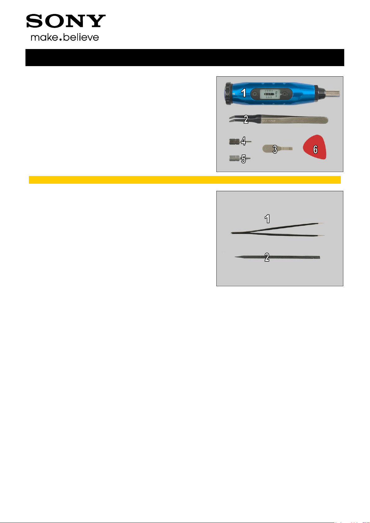
2 Tools
SPECIAL TOOLS
1. Torque Screwdriver
2. Flex Film Assembly Tool
3. Front Opening Tool
4. Bits(T5)
5. Bits(JCIS No 0)
6. Guitar Pick
For part no’s on the tools above, refer to the ‘Tools Catalogue/Matrix’!
STANDARD TOOLS
1. Tweezers
2. Nylon Pointer
Working Instruction Repair Instruction Mechanical/
1257-2928 Rev 2
Sony Mobile Communications AB – Company Internal
6(90)
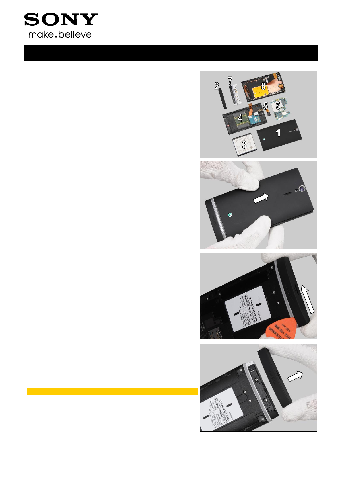
The disassembly is done in the following order:
1. Cover Rear Assy
2. Cover Bottom
3. Battery
4. Rear Frame Assy
5. Main Camera
6. Main PBA
7. Cover Transparent Assy
8. Cover Front Assy
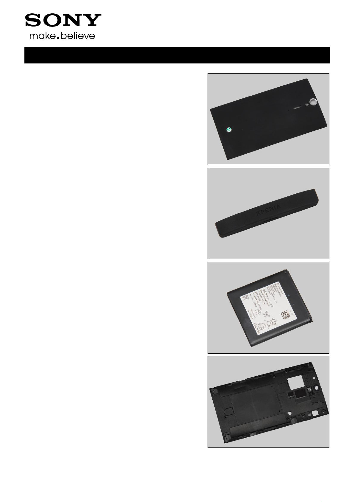
3.1 Cover Rear Assy
Push upwards to unsnap the hooks of the Cover Rear Assy
from the bottom gently and remove it.
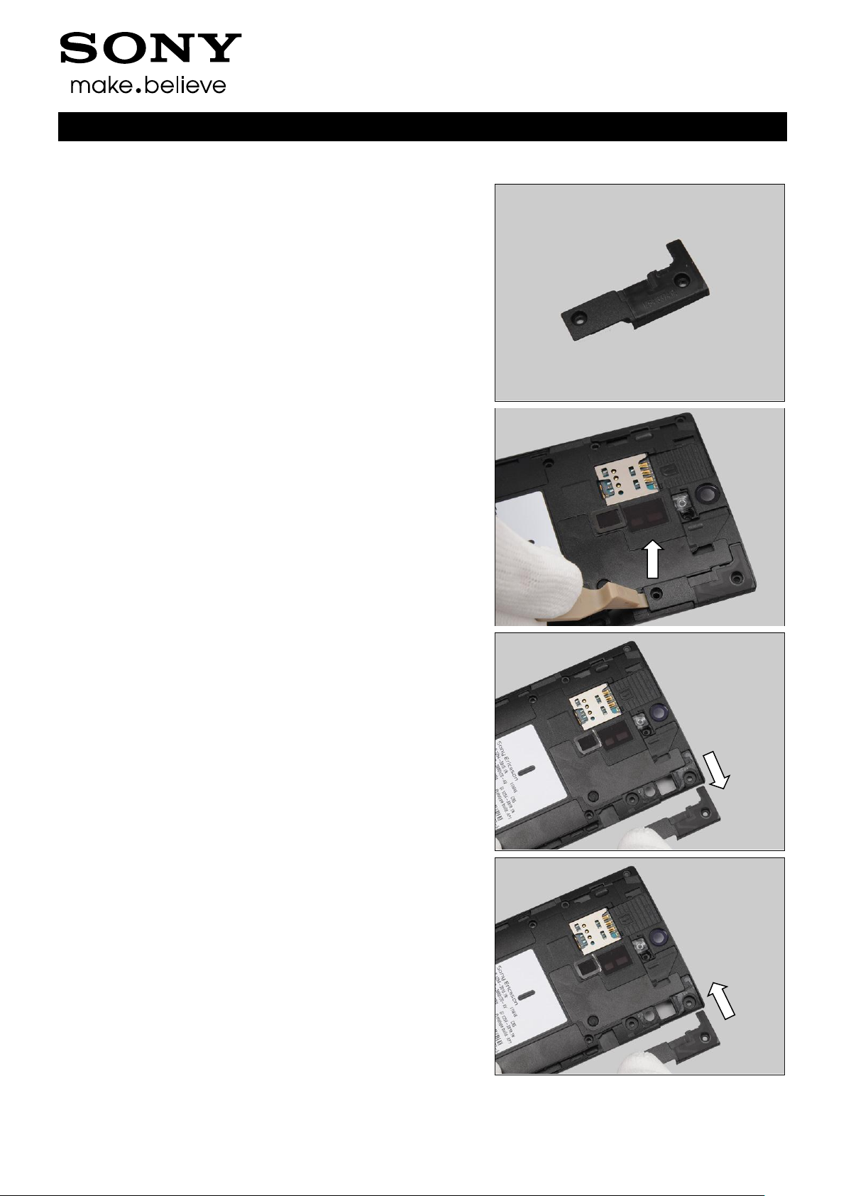
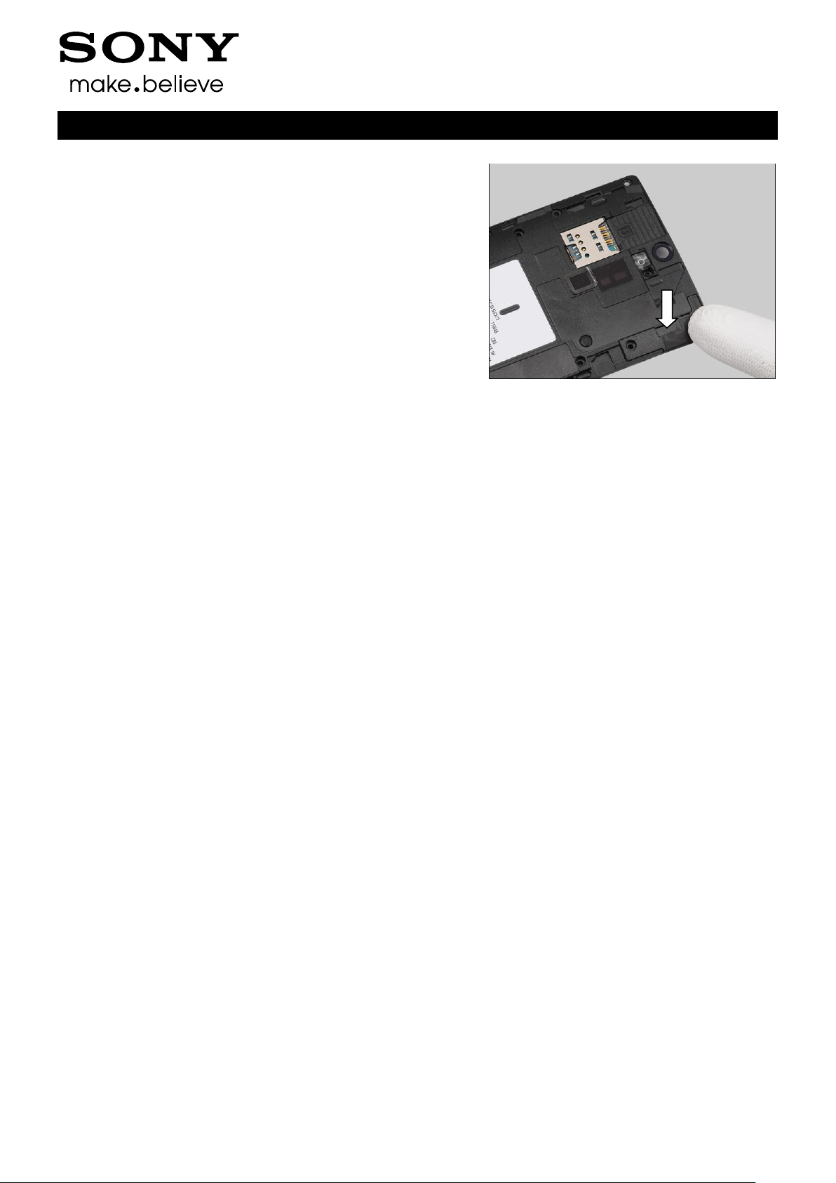
3.2 Cover Bottom
Push the Cover Bottom to show the gap between the Cover
Bottom and the Cover Transparent Assy with your fingers
and insert Guitar Pick to release the hooks of the Cover
Bottom.
Remove the Cover Bottom with your fingers.
Scrap! Not to be reused!
3 Disassembly
Working Instruction Repair Instruction Mechanical/
1257-2928 Rev 2
Sony Mobile Communications AB – Company Internal
7(90)
Disassembly
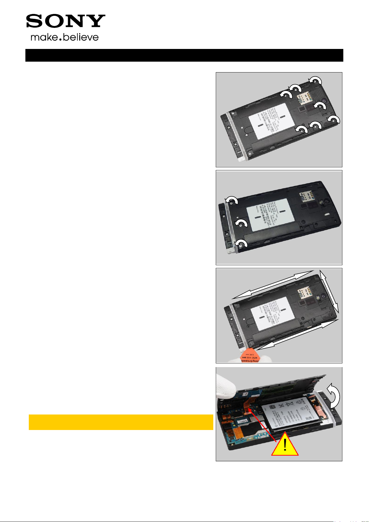
3.3 Battery
Remove the seven screws Len:3.5 Diam:1.4 by T5.
Remove the three screws Len:3.5 Diam:1.4M by Bits(JCIS
No 0).
Insert the Guitar Pick from the right bottom as shown in the
picture and gently slide back and forth to release the hooks
of the Rear Frame.
Raise the left side of the Rear Frame approximately 60°
from the right side.
Do not open the cover more than 60° and do not stretch
the NFC PFC!
Working Instruction Repair Instruction Mechanical/
1257-2928 Rev 2
Sony Mobile Communications AB – Company Internal
8(90)
Disassembly
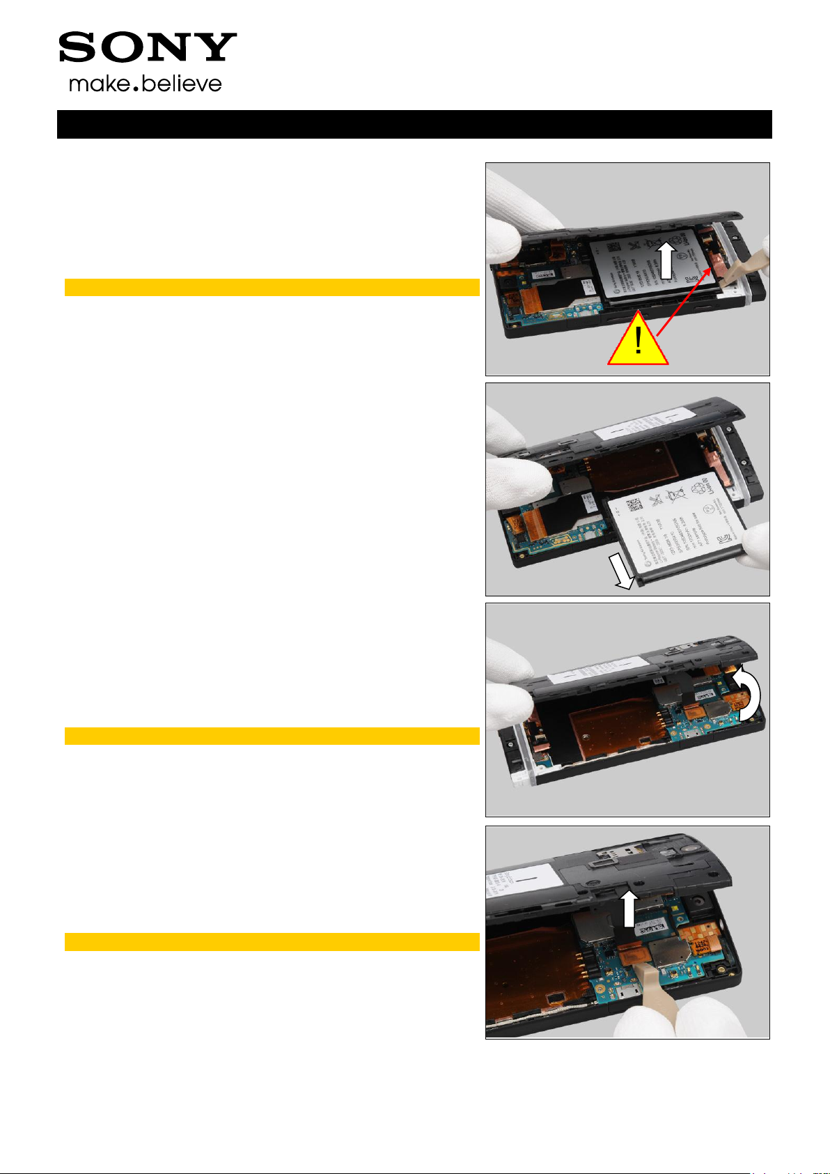
Insert the Front Opening Tool and raise the bottom of the
Battery to release it.
Do not touch the FPC area beside the Battery!
Remove the Battery.
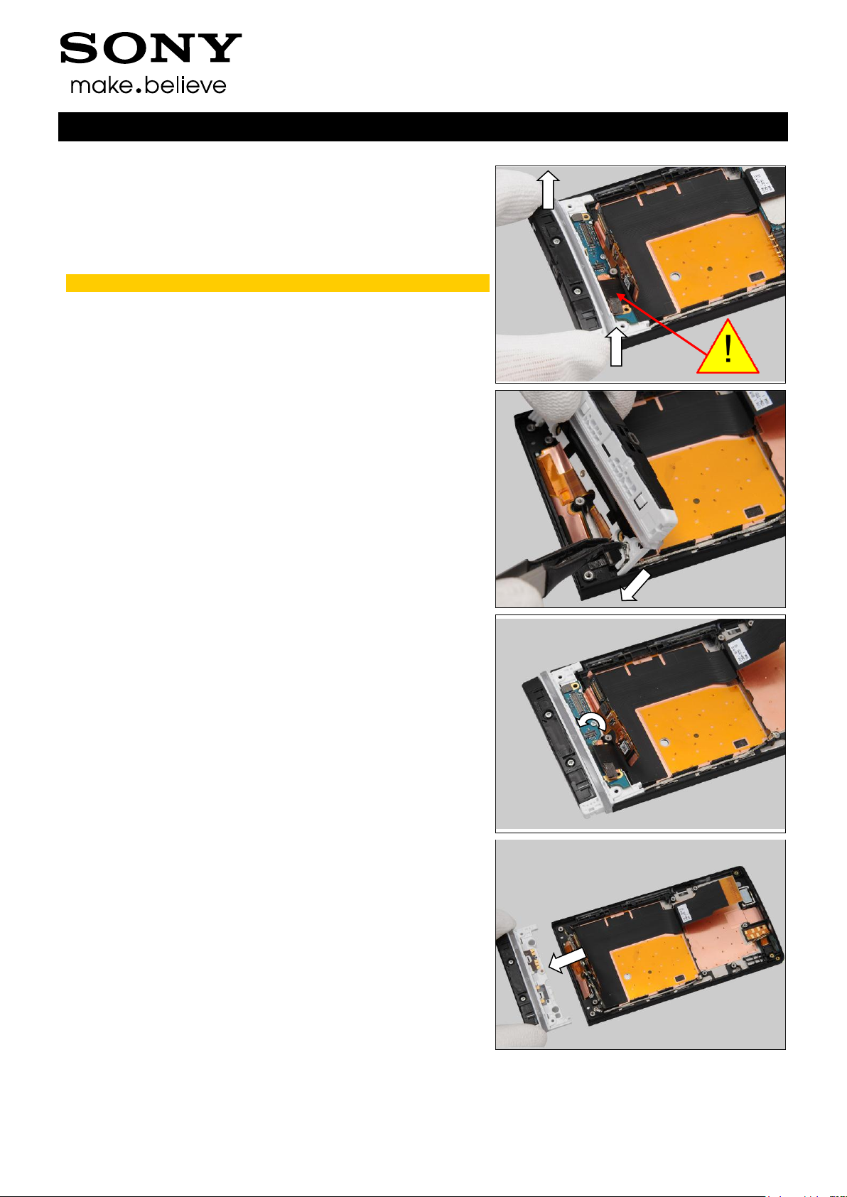
3.4 Rear Frame Assy
Change to raise another side of the Rear Frame.
Do not open the Rear Frame Assy more than 60°!
Unsnap the BtB connector by using the Front Opening Tool.
No conductive tools should be used!
Working Instruction Repair Instruction Mechanical/
1257-2928 Rev 2
Sony Mobile Communications AB – Company Internal
9(90)
Disassembly
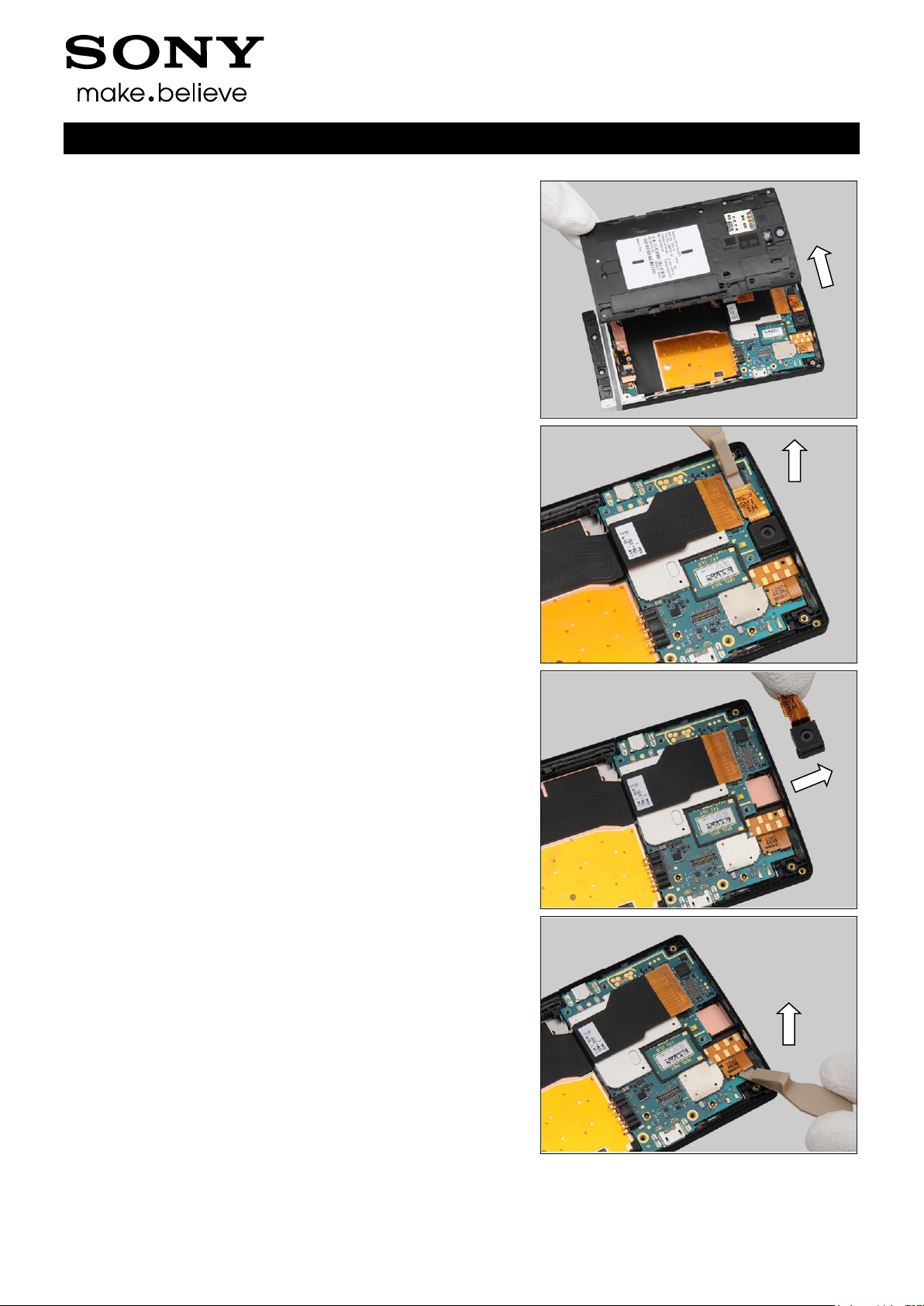
Remove the Rear Frame Assy with your fingers.
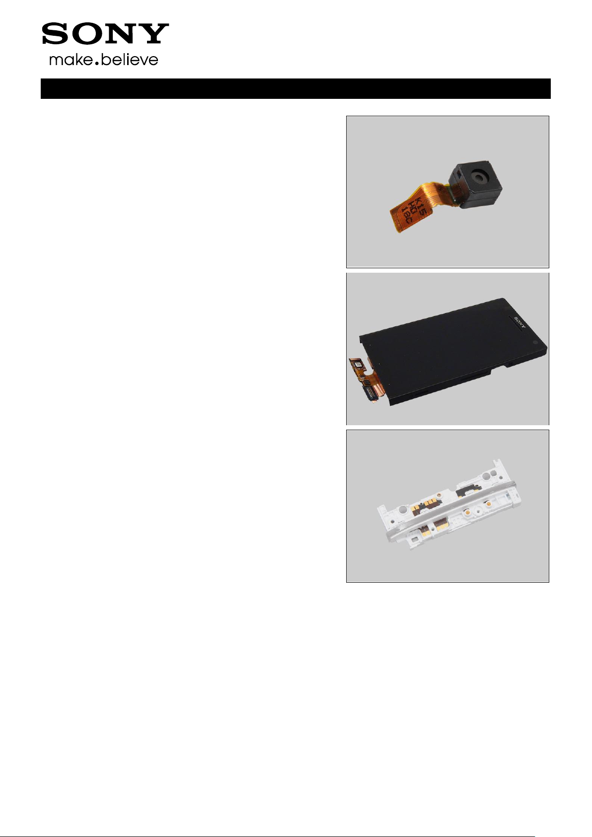
3.5 Main Camera
Unsnap the BtB connector by using the Front Opening Tool.
Remove the Main Camera with your fingers.
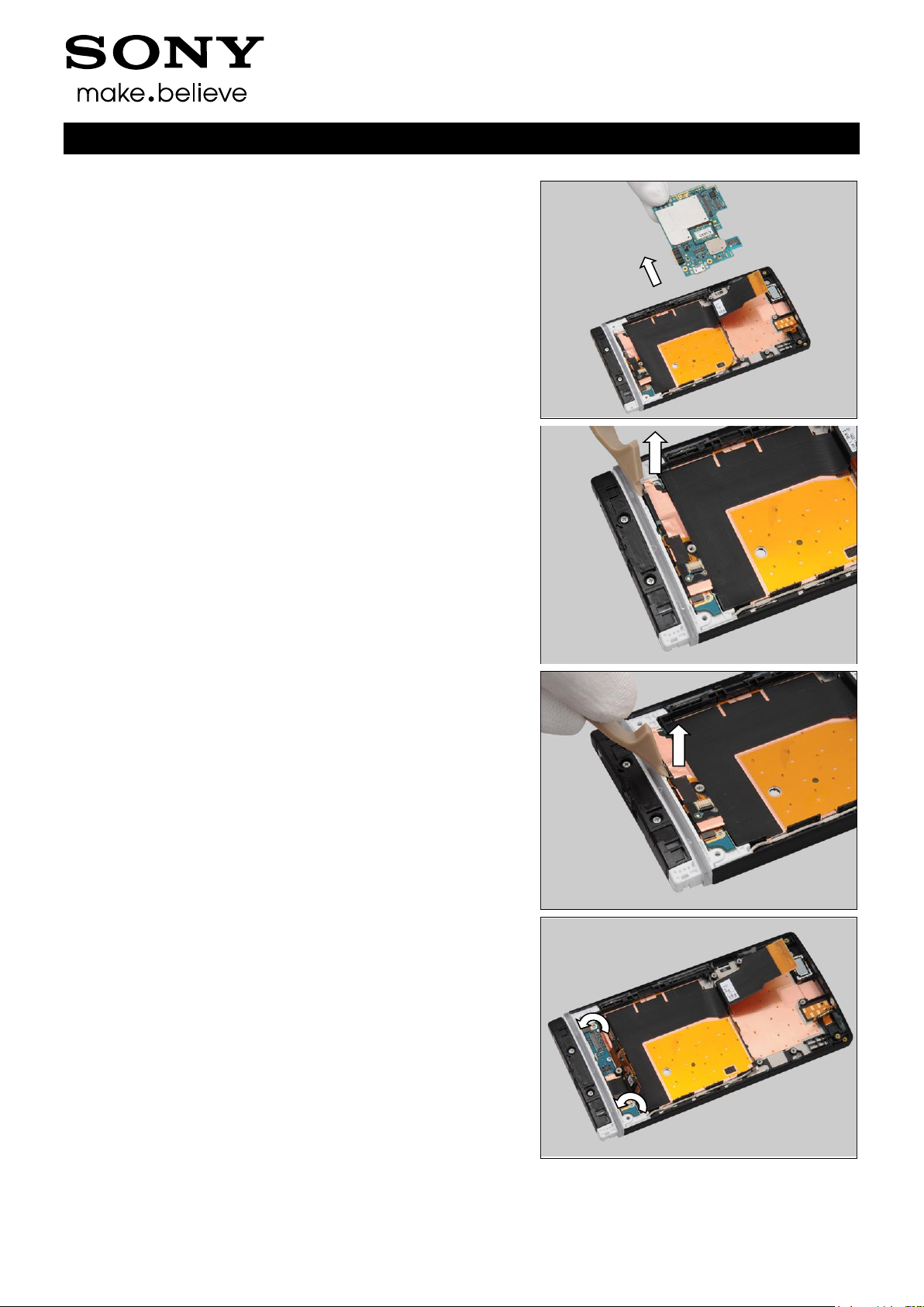
3.6 Main PBA
Unsnap the FPC Jack BtB connector by using the Front
Opening Tool.
Working Instruction Repair Instruction Mechanical/
1257-2928 Rev 2
Sony Mobile Communications AB – Company Internal
10(90)
Disassembly
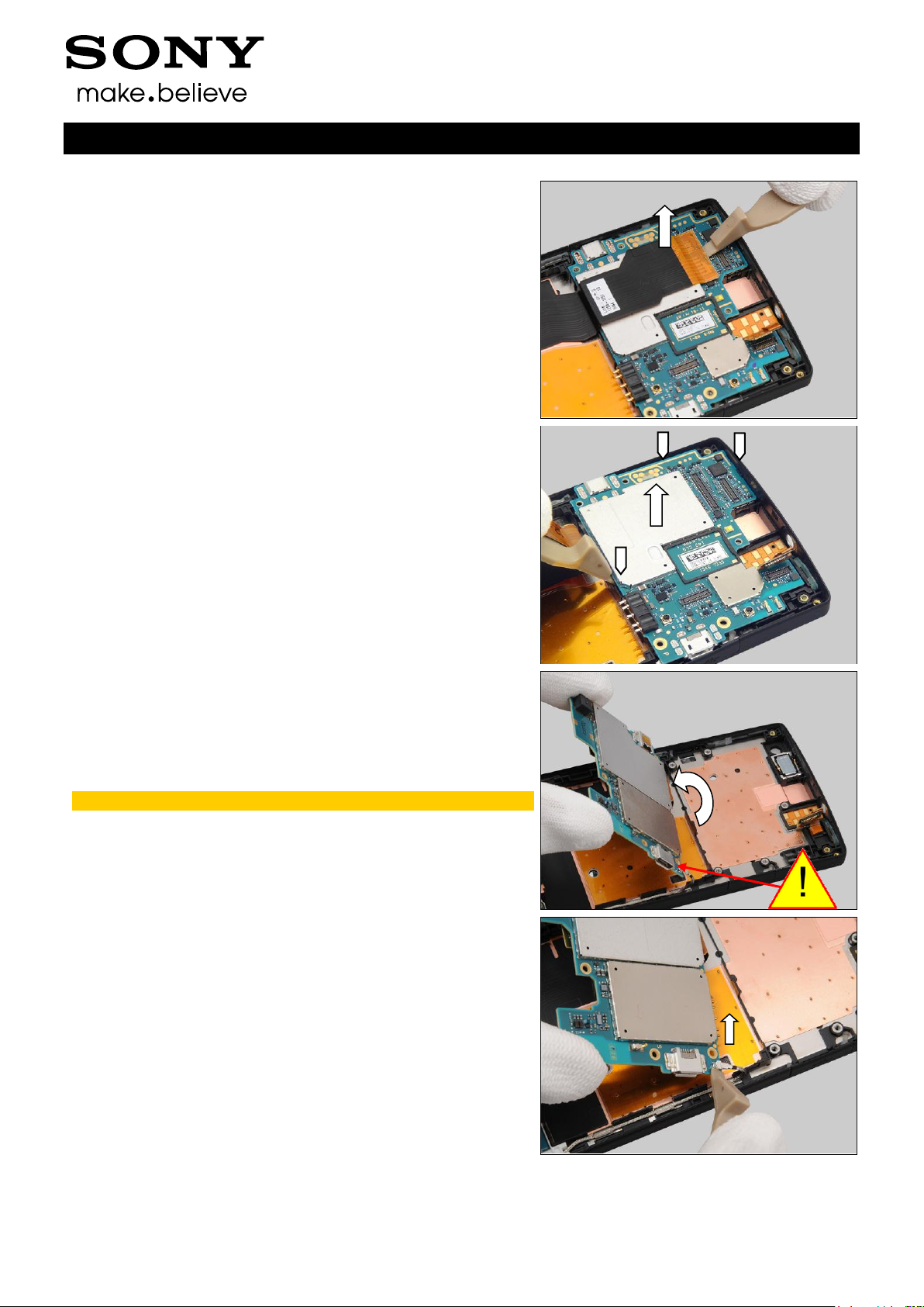
Unsnap the Main FPC BtB connector by using the Front
Opening Tool.
Insert the Front Opening Tool to release the Main PBA.
Turn the main PBA over gently.
Do not stretch the RF Cable!
Unsnap one side of the RF Cable by using the Front
Opening Tool.
Working Instruction Repair Instruction Mechanical/
1257-2928 Rev 2
Sony Mobile Communications AB – Company Internal
11(90)
Disassembly
Remove the Main PBA with your fingers.
3.7 Cover Transparent Assy
& Cover Front Assy
Unsnap the LCD BtB connector by using the Front Opening
Tool.
Unsnap the touch panel BtB connector by using the Front
Opening Tool.
Remove the two screws Len:3.5 Diam:1.4M by Bits(JCIS No
0).
Working Instruction Repair Instruction Mechanical/
1257-2928 Rev 2
Sony Mobile Communications AB – Company Internal
12(90)
Disassembly
Lift up the Cover Transparent and Turn it over gently.
Do not open the Sheet ACF Relay from the PBA!
Unsnap one side of the RF Cable by using the Flex Film
Assembly Tool.
Remove the one screw Len:2.0 Diam:1.4 by Bits(JCIS No
0).
Remove the Cover Transparent Assy.
Working Instruction Repair Instruction Mechanical/
1257-2928 Rev 2
Sony Mobile Communications AB – Company Internal
13(90)
4.1 Cover Rear Assy
Follow the 3.1 Disassembly instructions!
Prepare the new Cover Rear Assy.
Follow the 5.7 Reassembly instructions!
4.2 Cover Bottom
Follow the 3.2 Disassembly instructions!
Prepare the new Cover Bottom.
Follow the 5.6 Reassembly instructions!
4.3 Battery
Follow the 3.1 – 3.3 Disassembly instructions!
Prepare the new Battery.
Follow the 5.5 – 5.7 Reassembly instructions!
4.4 Rear Frame Assy
Follow the 3.1 – 3.4 Disassembly instructions!
Follow the 4.8, 4.9, 4.11, 4.36, Removal instructions!
Prepare the new Rear Frame Assy.
Follow the 4.8, 4.9, 4.11, 4.16, 4.23, 4.24, 4.25, 4.26, 4.33,
4.35, 4.37, 4.48, 4.49 Installation instructions!
Follow the 5.4 – 5.7 Reassembly instructions!
4 Replacement
Working Instruction Repair Instruction Mechanical/
1257-2928 Rev 2
Sony Mobile Communications AB – Company Internal
14(90)
Replacement
4.5 Main Camera
Follow the 3.1 – 3.5 Disassembly instructions!
Prepare a new Main Camera.
Follow the 4.17 Installation instructions!
Follow the 5.3 – 5.7 Reassembly instructions!
4.6 Cover Front Assy
Follow the 3.1 – 3.7 Disassembly instructions!
Follow the 4.10, 4.12, 4.14, 4.22, 4.28, 4.30, 4.31, 4.32, 4.38
Removal instructions!
Prepare a new Cover Front Assy.
Follow the 4.10, 4.12, 4.14, 4.18, 4.20, 4.22, 4.28, 4.29,
4.30, 4.31, 4.32, 4.38 Installation instructions!
Follow the 5.1 – 5.7 Reassembly instructions!
4.7 Cover Transparent Assy
Follow the 3.1 – 3.4, 3.7 Disassembly instructions!
Follow the 4.13, 4.34, 4.36 Removal instructions!
Prepare the new Cover Transparent Assy.
Follow the 4.13, 4.27, 4.34, 4.36 Installation instructions!
Follow the 5.1, 5.4 – 5.7 Reassembly instructions!
Working Instruction Repair Instruction Mechanical/
1257-2928 Rev 2
Sony Mobile Communications AB – Company Internal
15(90)
Follow the 3.1 – 3.4 Disassembly instructions!
Follow the 4.24 Removal instructions!
Carry out the Removal as described below.
Prepare the new Ant GPS.
Carry out the Installation as described below.
Follow the 4.39 Installation instructions!
Follow the 4.24 Installation instructions!
Follow the 5.4 – 5.7 Reassembly instructions!
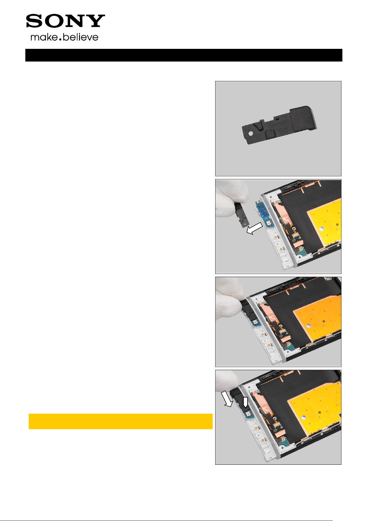
REMOVAL
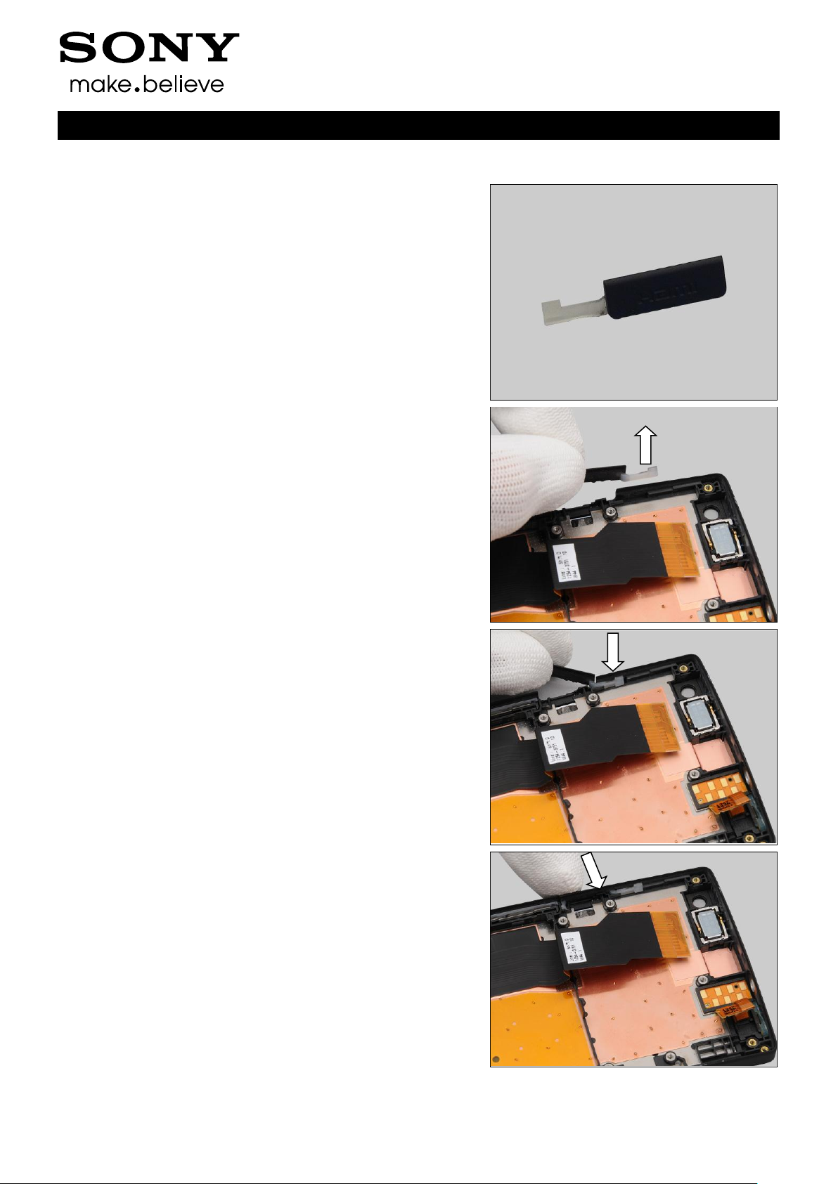
Detach the Ant GPS by using the Front Opening Tool.
Remove it with your fingers.
INSTALLATION
Place the new Ant GPS in the correct position.
Replacement
4.8 Ant GPS
Working Instruction Repair Instruction Mechanical/
1257-2928 Rev 2
Sony Mobile Communications AB – Company Internal
16(90)
Press to secure its attachment.
Replacement: Ant GPS
Working Instruction Repair Instruction Mechanical/
1257-2928 Rev 2
Sony Mobile Communications AB – Company Internal
17(90)
Follow the 3.1 – 3.4 Disassembly instructions!
Follow the 4.23 Removal instructions!
Carry out the Removal as described below.
Prepare the new Audio Jack
Follow the 4.23 Installation instructions!
Carry out the Installation as described below.
Follow the 5.4 – 5.7 Reassembly instructions!
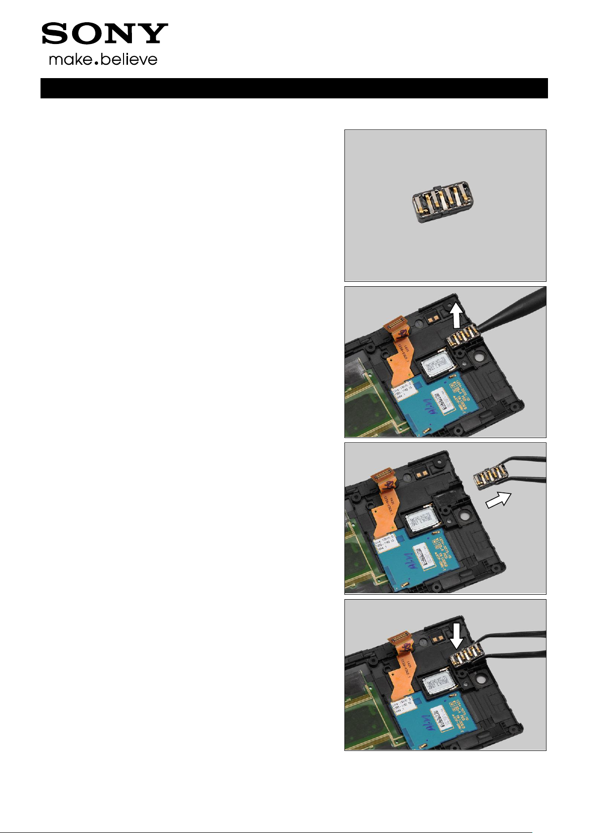
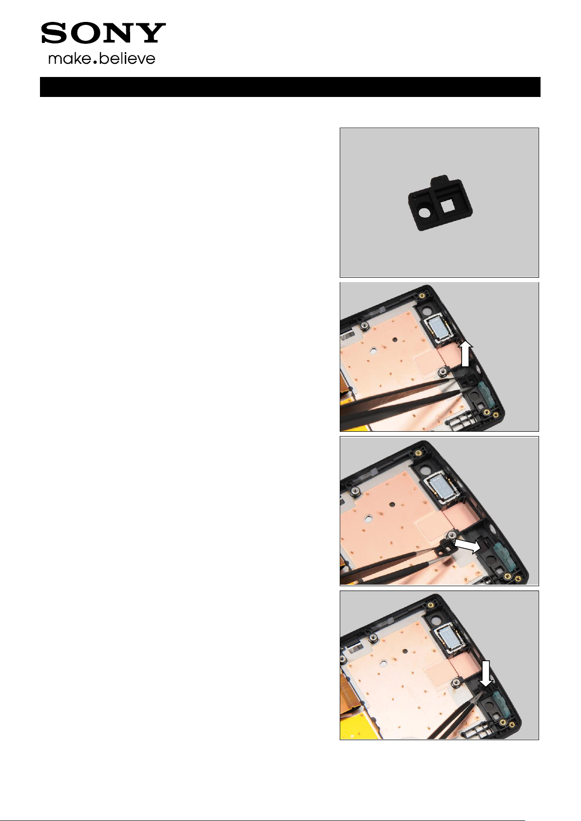
REMOVAL
Insert the Nylon Pointer into the hole of the Audio Jack
connector to release it.
Remove the Audio Jack by using the Flex Film Assembly
Tool.
INSTALLATION
Place the new Audio Jack into its socket.
Replacement
4.9 Audio Jack
Working Instruction Repair Instruction Mechanical/
1257-2928 Rev 2
Sony Mobile Communications AB – Company Internal
18(90)
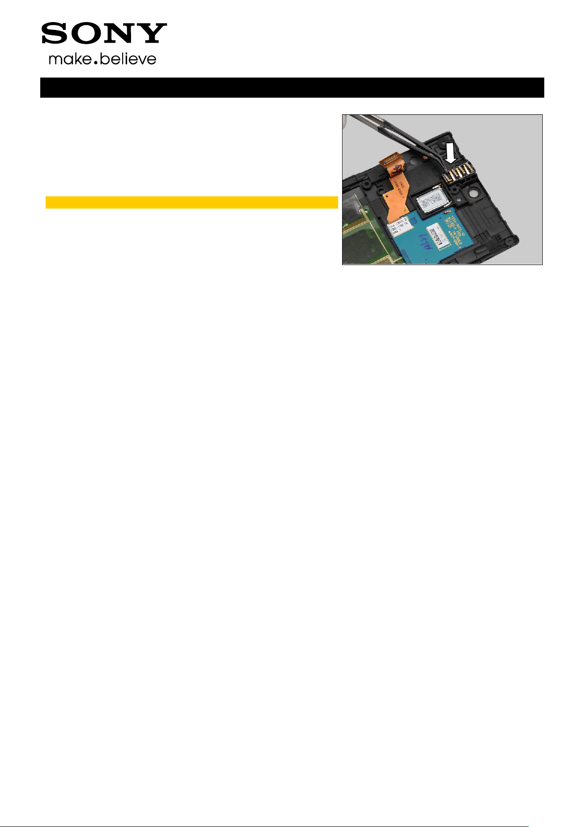
Press to secure its position by using the Flex Film Assembly
Tool.
Do not touch the contact pins on the Audio Jack!
Replacement: Audio Jack
Working Instruction Repair Instruction Mechanical/
1257-2928 Rev 2
Sony Mobile Communications AB – Company Internal
19(90)
Follow the 3.1 – 3.6 Disassembly instructions!
Carry out the Removal as described below.
Prepare the new Cap HDMI.
Carry out the Installation as described below.
Follow the 5.2 – 5.7 Reassembly instructions!
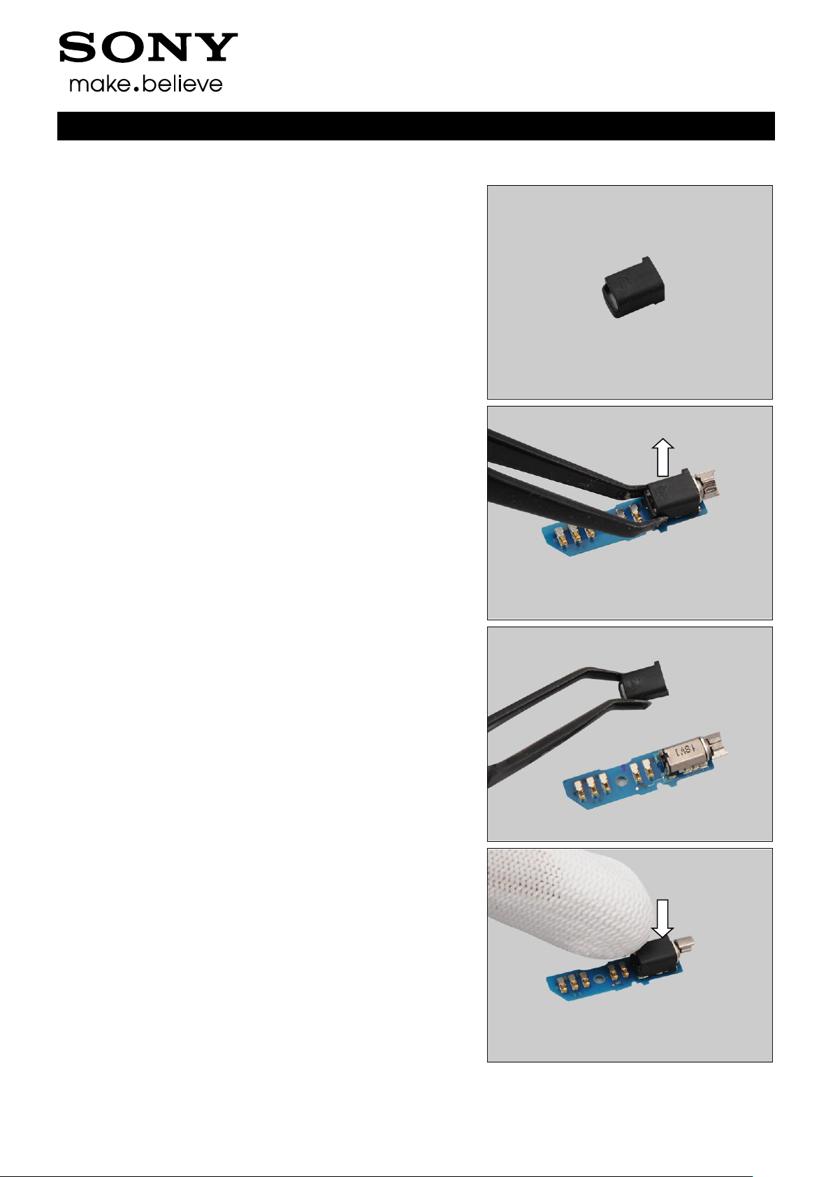
REMOVAL
Lift up the Cap HDMI to remove it with your fingers.
INSTALLATION
Place the Cap HDMI in the correct position as shown in the
picture.
Press to secure its position.
Replacement
4.10 Cap HDMI
Working Instruction Repair Instruction Mechanical/
1257-2928 Rev 2
Sony Mobile Communications AB – Company Internal
20(90)
Replacement
Follow the 3.1 Disassembly instructions!
Carry out the Removal as described below.
Prepare the new Cap RF.
Carry out the Installation as described below.
Follow the 5.7 Reassembly instructions!
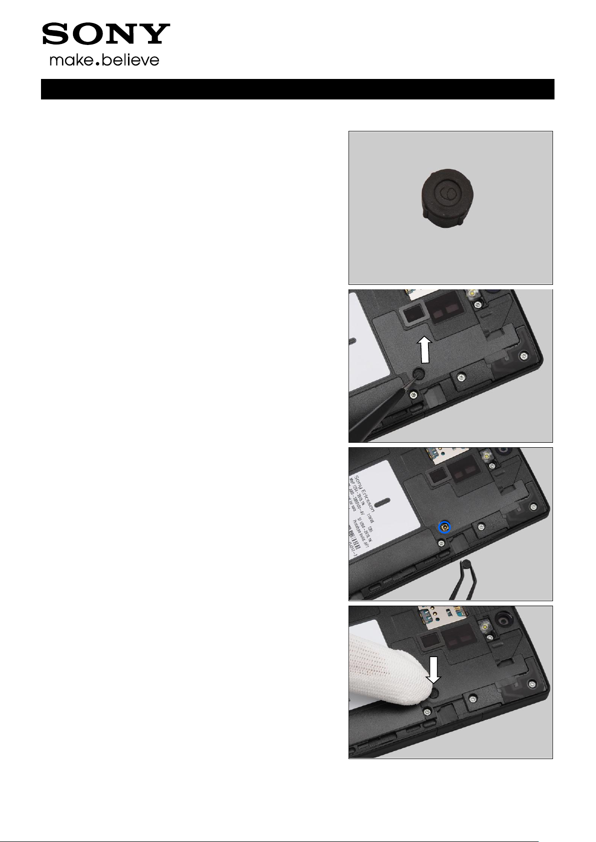
REMOVAL
Lift up the Cap RF by using the Tweezers and remove it.
INSTALLATION
Place the new Cap RF in the correct position.
Press the Cap RF into its proper position.
4.11 Cap RF
Working Instruction Repair Instruction Mechanical/
1257-2928 Rev 2
Sony Mobile Communications AB – Company Internal
21(90)
Carry out the Removal as described below
Prepare the new Cap USB.
Carry out the Installation as described below.
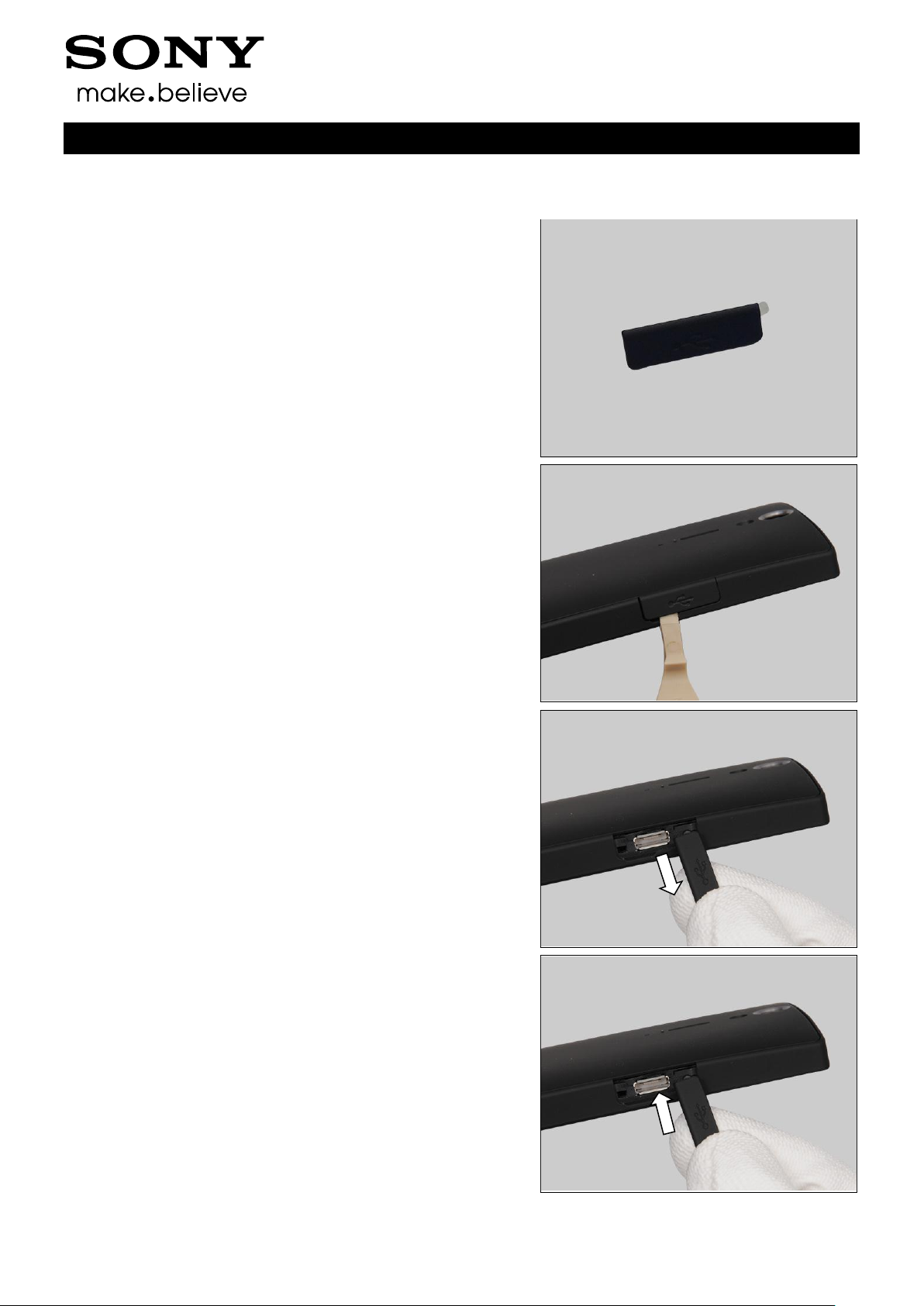
REMOVAL
Insert the Front Opening Tool to release the Cap USB.
Pull to release the Cap USB from its hole with your fingers.
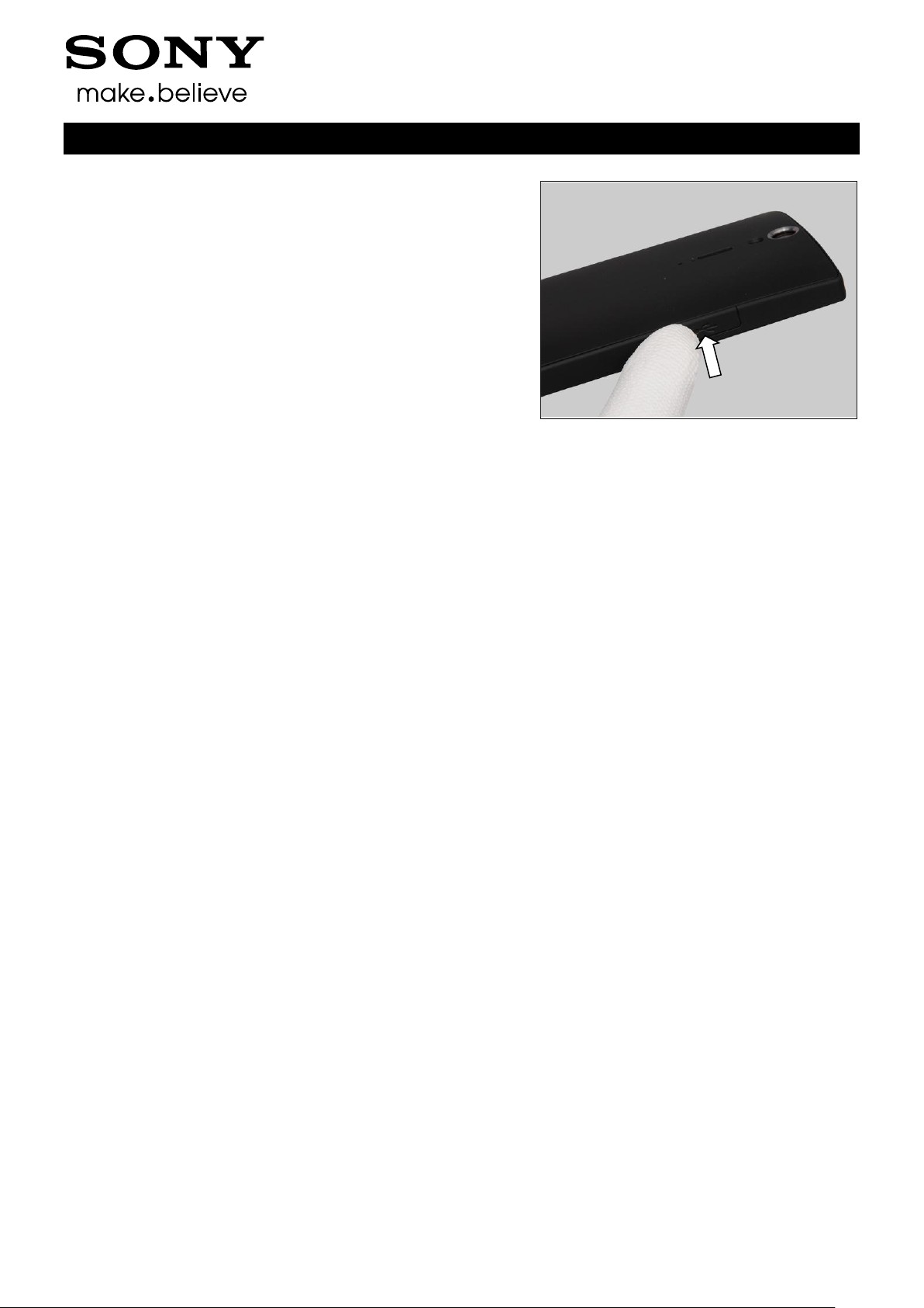
INSTALLATION
Insert the Cap USB into its hole with your fingers.
Replacement
4.12 Cap USB
Working Instruction Repair Instruction Mechanical/
1257-2928 Rev 2
Sony Mobile Communications AB – Company Internal
22(90)
Press to secure its position.
Replacement: Cap USB
Working Instruction Repair Instruction Mechanical/
1257-2928 Rev 2
Sony Mobile Communications AB – Company Internal
23(90)
Follow the 3.1 – 3.4 Disassembly instructions!
Follow the 4.34 Removal instruction!
Carry out the Removal as described below.
Prepare the new Carrier Holder Bottom.
Carry out the Installation as described below.
Follow the 4.34, 4.21 Installation instructions!
Follow the 5.4 – 5.7 Reassembly instructions!
REMOVAL
Remove the Carrier Holder Bottom with your fingers.
INSTALLATION
Place the Carrier Holder Bottom in the correct position.
Press to secure its position.
The guiding hole must be aligned accurately between
the Carrier Holder Bottom and the PBA Bottom!
Replacement
4.13 Carrier Holder Bottom
Working Instruction Repair Instruction Mechanical/
1257-2928 Rev 2
Sony Mobile Communications AB – Company Internal
24(90)
Follow the 3.1 – 3.6 Disassembly instructions!
Follow the 4.28 Removal instructions!
Carry out the Removal as described below.
Prepare the new Carrier Holder Proximity Sensor.
Carry out the Installation as described below.
Follow the 4.28 Installation instructions!
Follow the 5.2 – 5.7 Reassembly instructions!
REMOVAL
Detach the Carrier Holder Proximity Sensor by using the
Tweezers and remove it.
INSTALLATION
Place the Carrier Holder Proximity Sensor in the correct
position.
Press to secure its position.
Working Instruction Repair Instruction Mechanical/
Replacement
4.14 Carrier Holder Proximity Sensor
1257-2928 Rev 2
Sony Mobile Communications AB – Company Internal
25(90)
Follow the 3.1 – 3.4 Disassembly instructions!
Follow the 4.34, 4.13, 4.36 Removal instructions!
Carry out the Removal as described below.
Prepare the new Carrier Vibrator.
Carry out the Installation as described below.
Follow the 4.34, 4.13, 4.36 Installation instructions!
Follow the 5.4 – 5.7 Reassembly instructions!
REMOVAL
Detach the Carrier Vibrator by using the Flex Film Assembly
Tool and remove it.
INSTALLATION
Place the new Carrier Vibrator in the correct position.
Press to secure its position.
Replacement
4.15 Carrier Vibrator
Working Instruction Repair Instruction Mechanical/
1257-2928 Rev 2
Sony Mobile Communications AB – Company Internal
26(90)
Follow the 3.1 Disassembly instructions!
Carry out the Removal as described below.
Prepare the new Core Unit Label.
Carry out the Installation as described below.
Follow the 5.7 Reassembly instructions!
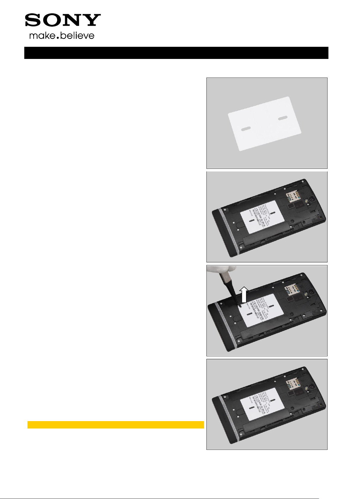
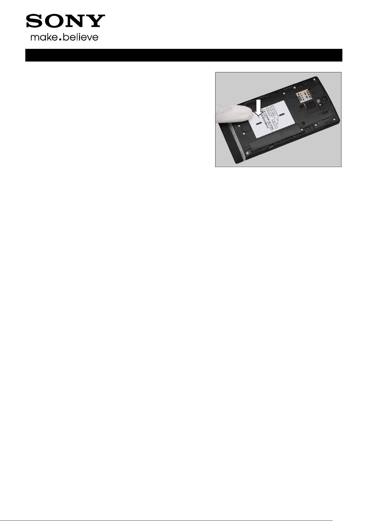
REMOVAL
Read the old Label Core Unit and write the information into
the ‘LabelMake’ program.
Carefully remove the Label by using the Flex Film Assembly
Tool.
INSTALLATION
Check that the proper label format is loaded in the Zebra
printer and write a new Label by using the ‘Label Make’
software.
One label only is allowed!
Replacement
4.16 Core Unit Label
Working Instruction Repair Instruction Mechanical/
1257-2928 Rev 2
Sony Mobile Communications AB – Company Internal
27(90)
Press along the surface to make Label securely attached.
Replacement: Core Unit Lable
Working Instruction Repair Instruction Mechanical/
 Loading...