

Sony XCG-CG160,XCG-CG160C,XCG-CG510C,XCG-CG510,XCG-CG240,XCG-CG240C Technical Manual

Digital Video
Camera Module
C-283-100-12 (1)
Technical Manual
XCG-CG160/CG160C
XCG-CG240/CG240C
XCG-CG510/CG510C
© 2015 Sony Corporation

Table of Contents
Overview
Features ...................................................................3
Phenomena Specific to Image Sensors .................4
System Components ...............................................5
Connection ..............................................................6
Location and Function of Parts and
Operation ................................................................7
Front/Top/Bottom ...............................................7
Using a tripod .....................................................7
Rear .....................................................................8
Connecting the cables .........................................8
When mounting the camera ................................9
Connections
Network Settings ..................................................10
Using Persistent IP ............................................10
Using DHCP .....................................................10
Using LLA ........................................................10
Packet Size ........................................................10
Packet Delay .....................................................10
Network connection speed ...................................11
Trigger Signal Input ............................................12
Trigger signal polarity ......................................12
GPIO Connector ..................................................13
Functions
Partial Scan ..........................................................15
Binning (XCG-CG160 only) ................................15
Drive mode ............................................................16
Multi ROI (XCG-CG160/CG160C only) ...........17
Output format ......................................................18
Image flip (Same level as output format) ...........20
Gain .......................................................................20
Manual gain ......................................................20
Auto gain (AGC) ..............................................20
Area gain ...........................................................21
Shutter (Exposure) ...............................................21
Configuring the setting .....................................21
Auto exposure (AE) ..........................................22
Combination of Continuous AGC and Continuous
AE ..........................................................................22
Trigger Control ....................................................23
Free run/trigger mode / PTP (IEEE1588) .........23
Special trigger ...................................................26
Burst trigger ......................................................27
FreeSetSequence ...............................................28
Trigger source ...................................................30
Trigger inhibition ..............................................30
Trigger delay .....................................................30
Trigger counter .................................................30
Trigger range limit ............................................31
Frame Rate ........................................................... 32
Auto frame rate ................................................ 32
Specifying frame rate ....................................... 32
Displaying frame rate ....................................... 32
Fastest frame rate for partial scanning ............. 33
Frame counter ...................................................... 35
Timing Chart ....................................................... 35
Trigger latency/Exposure time ......................... 35
Trigger Overlap ................................................ 36
Memory shot .................................................... 36
White Balance ...................................................... 38
LUT ....................................................................... 38
Binarization ...................................................... 38
5-point interpolation ......................................... 38
Arbitrary setting ............................................... 39
Save LUT ......................................................... 39
Color Matrix Conversion .................................... 39
3 × 3 filter ............................................................. 40
Test Chart Output ............................................... 40
GPIO ..................................................................... 41
GPI ................................................................... 41
GPO .................................................................. 41
Status LED ........................................................... 43
Temperature Readout Function ......................... 43
Defect Correction ................................................. 43
Shading Correction ............................................. 44
User Set .................................................................46
User set memory .............................................. 46
User ID .................................................................. 46
Saving and Startup .............................................. 46
Camera Information ........................................... 46
Restart .................................................................. 46
Command List ..................................................... 47
Specifications
Specifications ........................................................ 56
Spectral Sensitivity Characteristics (Typical
Values) .................................................................. 58
Dimensions ........................................................... 59
2

Overview
Before operating the unit, please read this manual
thoroughly and retain for future reference.
• Output: 8/10/12-bit, RGB 24-bit, YUV 24-bit
(YUV444), or YUV 16-bit (YUV422)
• Pixel defect correction function
• Shading correction function
• Area gain function
This unit is a digital video camera module that adopts
the 1000BASE-T/100BASE-TX interface.
This operating instruction of the digital video camera
module covers:
• XCG-CG160/CG240/CG510 (monochrome models)
• XCG-CG160C/CG240C/CG510C (color models)
In this document, we refer to “Digital Video Camera
Module” as “the unit”, “XCG-CG160/CG240/CG510”
as “Monochrome camera”, and “XCG-CG160C/
CG240C/CG510C” as “Color camera”.
Features
GigE Vision compliant
This unit supports GigE Vision Ver.2.0/Ver.1.2, and the
versions are switchable by changing the settings.
IEEE1588 compliant
This precision clock synchronization via network
protocol conforms to the defined IEEE1588 standard.
This unit can synchronize the exposures of multiple
cameras via an Ethernet cable.
External trigger shutter function
By synchronizing with an external trigger signal, any
shutter timing can be used.
Partial scan
The camera module can limit the number of video
output lines to achieve high frame rates, enabling highspeed image processing.
Body fixing
The screw holes to install the camera module are located
under the front panel (the image sensor reference plane).
Installing the camera module on the front panel
minimizes deviation of the optical axis.
LUT (Look Up Table)
You can switch to OFF or ON. When set to ON, you can
select from five preset values, such as inversion,
binarization, settable five-point approximations, etc.
Switching an Output Bit Length
You can select 8-bit output, 10-bit output, or 12-bit
output.
For color models, you can also select an output of RGB
24-bit, YUV 24-bit (YUV444), or YUV 16-bit
(YUV422).
High image quality
This unit produces stable output images, by adopting the
latest CMOS image sensors with a global shutter
function.
By adopting the square pixel image sensor, images can
be processed using the original aspect ratio without a
converting procedure.
The following models and resolutions of their image
sensors are shown below.
Model name Pixel number
XCG-CG160/CG160C 1,580,000-pixel
XCG-CG240/CG240C 2,350,000-pixel
XCG-CG510/CG510C 5,070,000-pixel
Various settings
Sending a command from the host device allows various
settings, including the following.
•Gain
•Shutter
• Partial scan
• Trigger control
• LUT (Look Up Table)
White balance control (color camera
only)
You can adjust the R and B level against G level to adjust
the white balance. This unit is also equipped with the
one-push white balance function, by which the camera
can automatically adjust the white balance.
Area gain function
You can set the gains between 0 to 32 times for a
preference position (up to 16 positions). If the set area is
duplicated, the low-numbered area takes priority.
Equipped with temperature sensor
This unit can readout the temperature inside of the
camera from the temperature sensor installed on the
module board. If the update interval of the temperature
sensor value is set to other than 0, the temperature
information can be sent to a PC application as event
data.
Defect correction function
This unit is equipped with the function that reduces the
sensor defect, and it can be switched On/Off.
3

Shading correction function
This unit is equipped with the function that corrects the
shadings caused by a light source and lens, and it can be
switched On/Off.
Phenomena Specific to Image Sensors
Binning function (XCG-CG160 only)
Adding 2 pixels in the vertical and horizontal directions
achieves higher sensitivity and frame rate.
Note
The following phenomena that may occur in images are
specific to image sensors.
They do not indicate a malfunction.
White flecks
Although the image sensors are produced with highprecision technologies, fine white flecks may be
generated on the screen in rare cases, caused by cosmic
rays, etc.
This is related to the principle of image sensors and is
not a malfunction.
The white flecks especially tend to be seen in the
following cases:
• when operating at a high environmental temperature
• when you have raised the gain (sensitivity)
• when using the slow shutter
Aliasing
When fine patterns, stripes, or lines are shot, they may
appear jagged or flicker.
4
System Components
a
cd e
fg
b
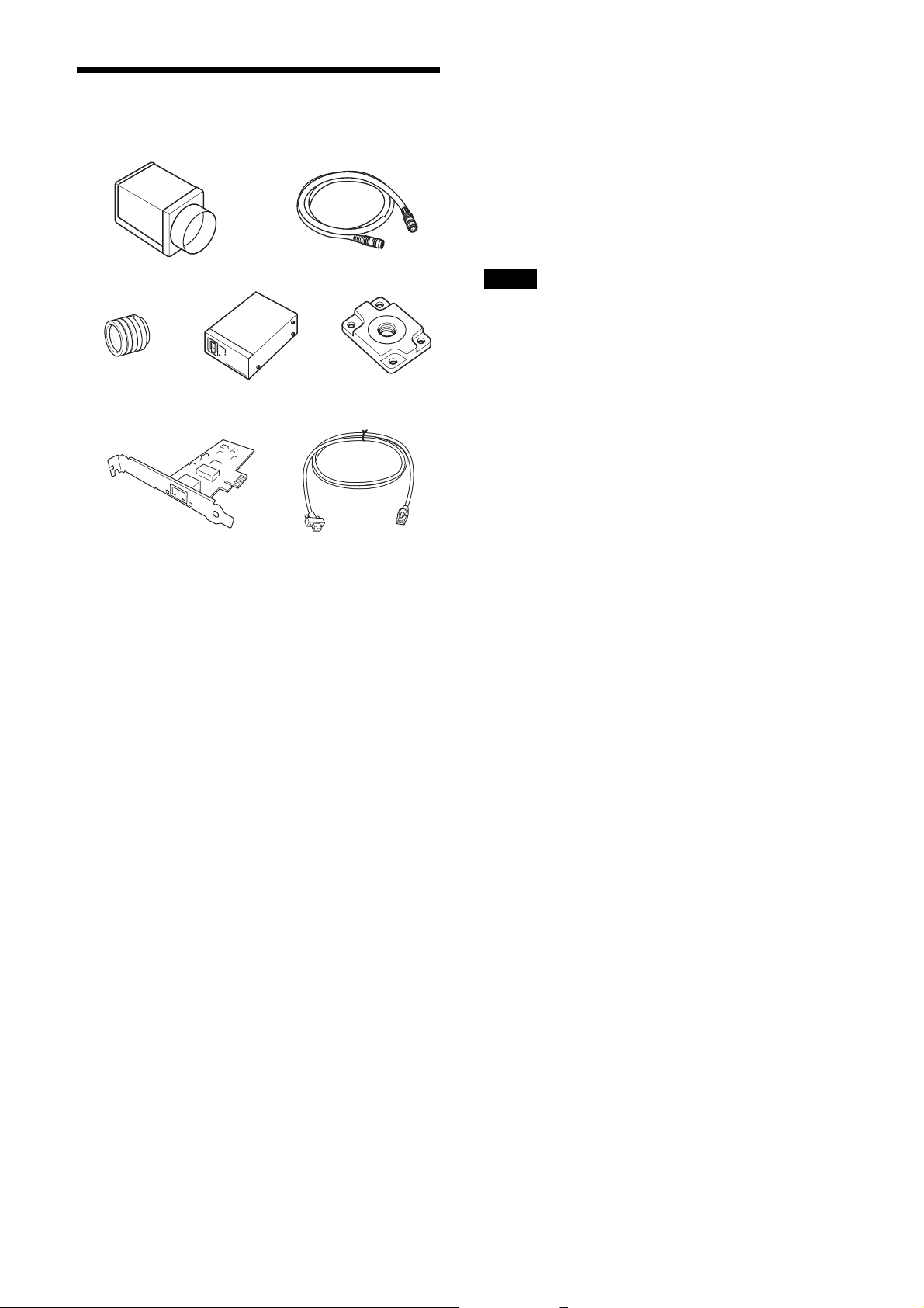
g LAN cable
This cable connects to the RJ45 connector on the rear
panel of the camera module.
Image/control signals are transmitted via this cable. Use
a LAN cable (CAT5e or higher standard) that supports
1000BASE-T (or allows 100BASE-TX when it is used).
Depending on the attributes of the LAN cable, images
may become less clear and the camera module may
become unstable. Be sure to use a LAN cable that has
sufficient noise reduction.
Note
When you connect the LAN cable of the unit to
peripheral device, use a shielded-type cable to prevent
malfunction due to radiation noise.
The video camera module system comprises the
following optional products (available separately).
a Video Camera Module
This is a small-size, high image-quality video camera
module that uses CMOS image sensors with a global
shutter function.
b Camera cable
This is attached to the DC IN connector of the camera
module and is used for power supply and exchange of
trigger signals.
For purchasing the cable, consult the dealer.
c C-mount lens
Use a suitable lens to fit the camera pixel count.
d DC-700/700CE camera adaptor
This is connected to the camera module to enable power
supply from ordinary AC power source.
e VCT-333I tripod adaptor
This attaches to the bottom of the camera module to fix
the camera module to a tripod.
f Camera module interface board
Install the board in the expansion slot of the host device
(ex: computer). Use a board that is appropriate for your
system and that supports 1000BASE-T (or allows
100BASE-TX when it is used) and jumbo packets.
5
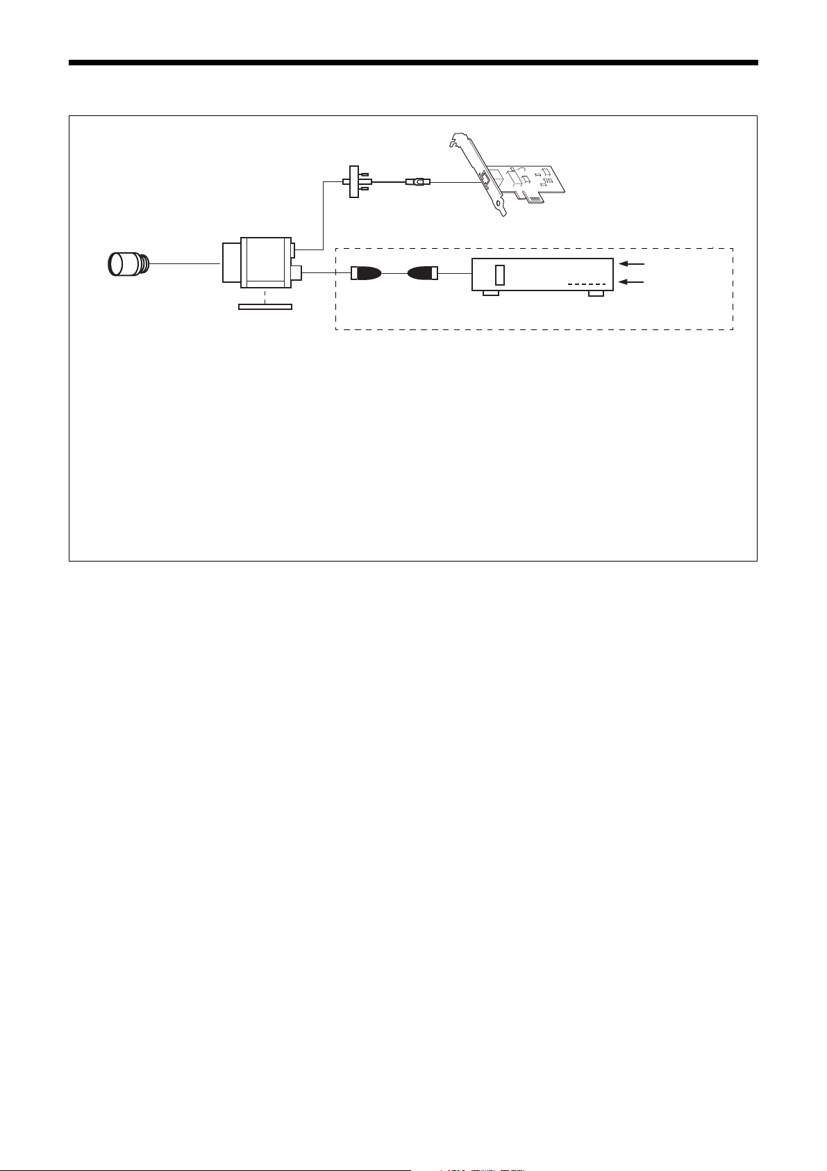
Connection
LAN cable
Camera module
C-mount lens
Camera cable
Tripod adaptor
VCT-333I
Power supply
You can supply power to the camera module using the following methods.
Using the RJ45 connector
This unit supports PoE (IEEE802.3af standard). By using a PoE-compatible LAN cable and camera module interface board or hub,
you can power, control, and output images from the camera using one LAN cable.
Using the DC IN connector
You can supply power via the DC IN connector using the power adapter.
Use DC-700/700CE which is the stable power source free from ripple or noise.
If the HUB supports PoE, the items within the dashed line are not necessary.
Camera module interface board
AC
TRIG
Camera adaptor
DC-700/700CE
Heat dissipation
For heat dissipation, refer to When mounting the camera (see page 9).
6
Location and Function of Parts and Operation
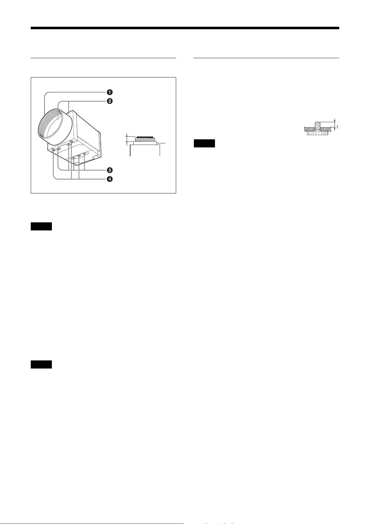
Front/Top/Bottom
a
a Lens mount (C-mount)
Attach any C-mount lens or other optical equipment.
Note
Use a C-mount lens with a protrusion (a) extending from
the lens mount face (b) of 10 mm (13/32 inch) or less.
The performance of a lens may change according to the
aperture level.
If the resolution is not enough, adjust the aperture level.
b
Using a tripod
To use the tripod, install the tripod adaptor VCT-333I
(not supplied) on the camera module.
Use a tripod screw with a protrusion (4) extending from
the installation surface, as follows, and tighten it, using
a screwdriver. Be sure that the protrusion (4) does not
exceed 5.5 mm (0.2 in.) in length.
Length 4.5 to 5.5 mm
Length 0.18 to 0.22 inches
Note
If you install a tripod adapter (not supplied), use the
screws provided.
b Guide screw holes (Top)
c Guide screw holes/Tripod screw holes (bottom)
When using a tripod, use these four screw holes to attach
a VCT-333I tripod adaptor.
d Reference screw holes (bottom)
These precision screw holes are for locking the camera
module. Locking the camera module into these holes
secures the optical axis alignment.
Note
Refer to XCG-CG240 Demensions in page 59 for about
the position/size of the Guide hole and the Reference
hole.
7
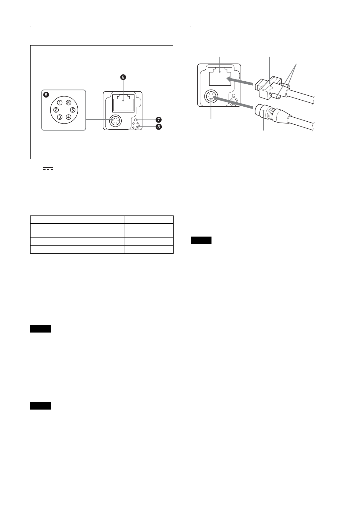
Rear
Connecting the cables
e (DC power input) connector (6-pin)
You can connect a camera cable to input the +12 V DC
power supply. The pin configuration of this connector is
as follows.
(Refer to Fig.
6 above for the pin assignment of the
connector.)
Pin No. Signal Pin No. Signal
1 DC input (10.5 V
to 15 V)
2 GPI1 (ISO +) 5 ISO –
3 GPI2/GPO2 6 GND
4 GPI3/GPO3
(GPO3 (ISO +)*)
*XCG-CG160/CG160C only
Connect the camera cable (5) to the DC IN connector
(2) and connect the LAN cable (3) to the RJ45
connector (1) respectively. If you use a camera module
interface board or a hub that supports PoE, you can
operate the camera even if you do not connect the
camera cable to the DC IN connector. When you connect
the LAN cable with fastening screws, turn the two
screws (4) on the connector to secure the cable tightly.
Connect the other end of the camera cable to the DC700/700CE and the other end of the LAN cable to the
camera module interface board or a hub.
Note
Do not supply power to the camera cable and LAN cable
at the same time.
f RJ45 connector
You can connect a LAN cable to this connector to
control the camera module from a host device to output
image to a host device. By using a PoE-compatible LAN
cable and camera module interface board or hub, you
can supply power using the LAN cable.
Note
For safety, do not connect the connector for peripheral
device wiring that might have excessive voltage to this
port. Follow the instructions for this port.
g Reset switch
The camera can be reset to the factory setting by
pressing the reset switch for more than 3 seconds while
the power is turned on.
Notes
• All the setting items will be deleted.
• Formatting is performed after operation.
Do not turn off the power for 1 minute after the LED
lights again.
h Status LED (Green)
Displays the unit status.
For details, see “Status LED” (page 43).
8
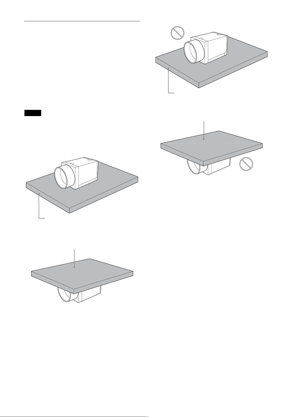
When mounting the camera
When the value read from temperature sensor is above
75 °C (167 °F), heat dissipation is required.
* For CG160/CG160C, in addition to the above
condition, use in environments where the difference
with the ambient temperature is 34°C or less.
To promote heat dissipation from the unit and maintain
performance, mount the camera to a metallic heat
dissipation plate.
Dimension of the heat dissipation plate: 160 mm ×
130 mm × t5 mm or more (Thermal conductivity:
16.3 W/m·K or more)
Plate that prevents heat dissipation
(made of wood, resin, etc.)
Notes
• When mounting the camera to the heat dissipation
plate, secure the camera tightly by using the reference
screw holes (see page 7) and screws.
• Do not mount the camera to a plate made of a material
such as wood or resin that prevents heat dissipation.
Metallic heat dissipation plate
Metallic heat dissipation plate
Plate that prevents heat dissipation
(made of wood, resin, etc.)
9

Connections
Network Settings
For the camera to be connected to a network, the
following address data must be properly specified:
• IP address
• Subnet mask
• Default gateway
The camera provides the following three methods for the
address data setting:
• Using Persistent IP
• Using DHCP
• Using Link Local Address (LLA)
Using Persistent IP
Use this method when the IP address to be assigned to
the camera has been specified in advance. When you use
a fixed IP, setting of subnet mask is necessary. To use
beyond the router, you need to set the default gateway as
well.
Packet Delay
The delay amount to be inserted between packets can be
set when sending them to a network. By increasing the
packet delay, you can reduce the network bandwidth that
the camera uses for sending packets. However, as the
amount of data sent in a certain time is decreased with
increased delay, the frame rate of output images of the
camera may be consequently decreased.
Using DHCP
The camera is equipped with a function to automatically
obtain an IP address by communicating with a DHCP
server on a network. When using the DHCP method for
IP address setting, the subnet mask and default gateway
values automatically obtained from the DHCP server are
also used.
Using LLA
If neither Persistent IP nor DHCP is used, or if an IP
address cannot be obtained from the DHCP server, the
IP address is determined by LLA. The IP address
determined by LLA will be 169.254.XXX.YYY, with
XXX and YYY automatically specified.
Packet Size
The amount of image data per packet can be set in bytes.
To permit the camera to operate properly, set the packet
size to a value less than the MTU of the network device
connected to the camera. Set the largest value in the
networks including the hub.
10
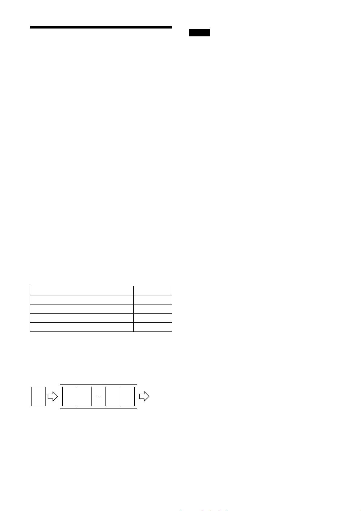
Network connection speed
This unit supports the connection with 1000Base-T
(1 Gbps) or 100Base-TX (100 Mbps).
When you connect the unit to the network, negotiate the
communication speed with the connected equipment
and start communication at a higher speed of that both
equipment are compatible with.
When using the unit with 100Base-TX connection, the
frame rate to be output is limited, because the output
data band width from the camera becomes narrow
compared to the 1000Base-T connection.
The camera has a buffer to store multiple images and all
of the shot images are stored once in the buffer.
The stored images are output from the camera in order
starting from the oldest image in the buffer.
Therefore, if the frame rate during shooting is faster than
the frame rate that can be output from the camera, the
image data will always be stored in the buffer, and the
time interval from shooting to image output becomes
large.
To avoid this situation, it is required to set the shooting
frame rate to the proper value when using 100Base-TX
connection.
The data rate of images is obtained by the following
formula:
Notes
• Any persistent IP address can be entered, but the
camera may become unable to be detected, depending
on the IP address setting. If this occurs, use a tool for
issuing ForceIP and set a persistent IP address again.
• When setting the parameters (Width, Height, and
PixelFormat) for calculating the payload size, stop
camera image output beforehand.
Data rate = Width
× Height × BPP × FPS
Width: Width of image
Height: Height of image
BPP: The number of bits per pixel depends on the
PixelFormat setting
Mono8/BayerRG8 8-bit
Mono10Packed/BayerRG10Packed 12-bit
Mono12Packed/BayerRG12Packed 12-bit
RGB8Packed/BRG8Packed/YUV8_UYV 24-bit
YUV422_8/YUV422_8_UYVY 16-bit
FPS: Frame rate [frame/sec]
It is possible to minimize delay by using the camera at a
frame rate where the data rate becomes low with a
margin against 100 Mbps.
Buffer
Image
sensor
Image nImage
n
Image 2Image
1
Image
output
11

Trigger Signal Input
Trigger signals can be input via the 2nd, 3rd, 4th pins of the DC IN connector, or the software command. Switchover of
the trigger signal can be changed via the TriggerSource register.
Trigger signal polarity
Positive refers to a trigger signal polarity activated while rising from Low to Hi, or during the Hi interval. Negative refers
to a trigger signal polarity activated while falling from Hi to Low, or during the Low interval.
Register Parameter Setting
TriggerActivation FallingEdge (0)
RisingEdge (1) Positive
DC IN connector specifications
2.0 µs or less
Negative
5 to 24 V (DC IN connector 2nd pin)
3.5 to 5.5 V (DC IN connector 3rd
and 4th pins*)
0 to 0.4 V
2.0 µs or less
10 µs to 2 s
1 frame time or more
Trigger input polarity = Negative
5 to 24 V (DC IN connector 2nd pin)
3.5 to 5.5 V (DC IN connector 3rd
and 4th pins*)
0 to 0.4 V
2.0 µs or less
10 µs to 2 s
2.0 µs or less
1 frame time or more
Trigger input polarity = Positive
* XCG-CG160/C160C: Unavailable. Dedicated to output.
Note
• When inputting a trigger signal to the camera using the DC-700/CE, use DC 5 V or less at the logical high level.
• Make sure to supply power to the camera module and confirm that the camera module is operating before inputting a
trigger signal. If you input trigger signal to a camera module without the power supplied, this may cause a malfunction
of the camera module.
12
GPIO Connector
The DC IN connector #2 is the GPI connector. #3 and #4 connectors can be set as GPI/GPO.* The trigger reset pin is
the DC IN connector 2nd pin (GPI1). If you are connecting an external device to the GPI or GPO connector, refer to the
circuit specifications below.
* #4 is GPO connector only for XCG-CG160/CG160C.
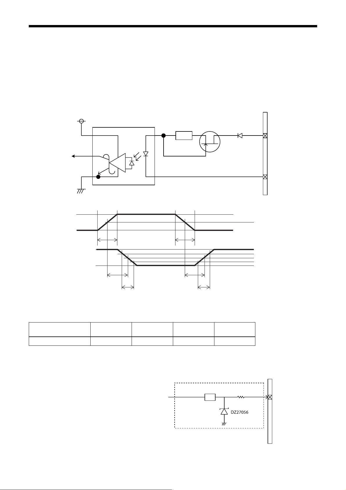
GPI circuit specifications
DC IN connector
3.3V
ACPL-M60
GPI1
Input level Low: 0 to 0.4 V, High: 5 to 24 V
180
MMBF4393LT1G
#2
DA2710100L
#5
5 V
0 V
*
3.3 V
0 V
TDF
FT
* Rising the input signal as soon as possible.
Example
Input voltage
[V]
5.0 167 297 192 358
TDF
[ns]
GPIO circuit specifications
XCG-CG160/CG160C
FT
[ns]
*
TDR
TDR
[ns]
RT
RT
[ns]
50%
90%
50%
10%
DC IN connector
GPI2/GPO2
13
SN74LVC1T45
180 Ω
#3
XCG-CG240/CG240C
XCG-CG510/CG510C
DC IN connector
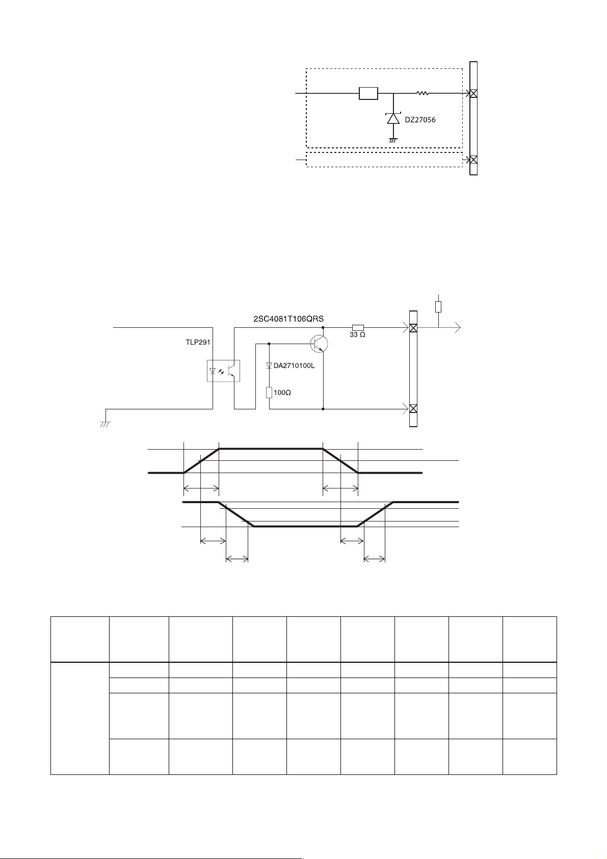
GPO circuit specifications
XCG-CG160/CG160C
GPO3
GPI2/GPO2
GPI3/GPO3
SN74LVC1T45
As GPI2/GPO2
Input level Low: 0 to 0.4 V, High: 3.5 to 5.5 V
Output level 0 to 3.3 V
180 Ω
External power source
(3.3 V to 24 V)
DC IN
connector
#4
Pull up resistance
#3
#4
#5
3.3 V
50%
0 V
3.3 V
0.9 V
TDF
FT
TDR
RT
90%
10%
Example
When connecting to an external power supply, be sure to use a pull-up resistor for a current limit of less than 50 mA.
Normal
temperature
Supply
voltage of
the output
[V]
3.3 470 Ω 5.07 0.75 0.49 24 35 0.916
5.0 820 Ω 4.98 0.73 0.63 28 46 0.909
12.0 Two
24.0 Eight 8200 Ω
Pull-up
resistor
(Use 1/16 W)
2200 Ω
resistors in
parallel
resistors in
parallel
Current
[mA]
TDF
[µs]
FT
[µs]
TDR
[µs]
RT
[µs]
Output
voltage
9.87 0.71 1.05 36 64 1.112
21.85 0.73 1.45 45 76 1.571
[V]
14
Functions
Binning (XCG-CG160 only)
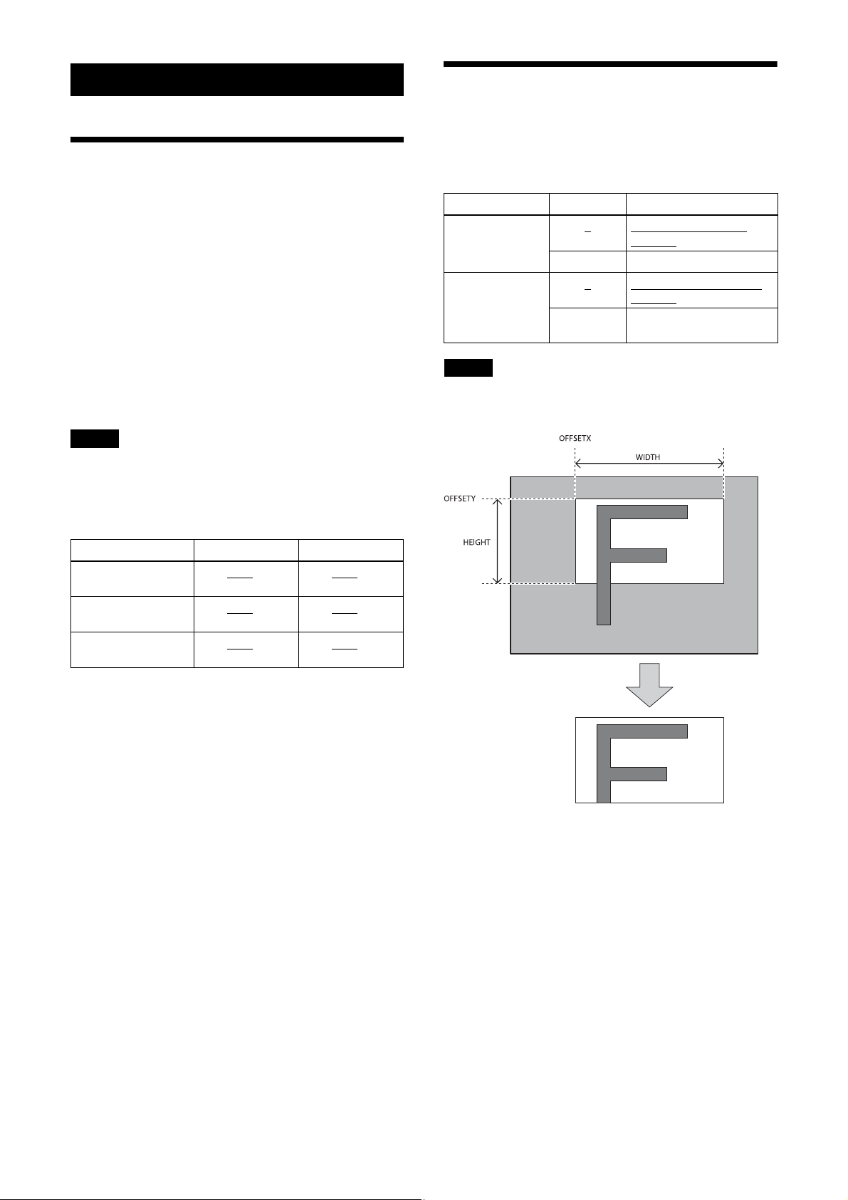
Partial Scan
Only the area selected from the effective pixel area can
be read out. Adding 2 pixels of vertical and horizontal
directions achieves higher sensitivity and frame rate.
The area size is selected by the Height and Width
registers, and the read beginning point is selected by the
OffsetX and OffsetY registers. Reducing Height
increases the frame rate, but changing the Width register
does not change the frame rate. Partial scan can be set
with or without a trigger.
OffsetX and OffsetY relate to Width and Height as
follows:
OffsetX + Width
OffsetY + Height
Note
Since the shutter setting has priority, use a shutter speed
high enough to enable partial scan at a higher frame rate.
Configurable range
XCG-CG160/
CG160C
XCG-CG240/
CG240C
XCG-CG510/
CG510C
≤ Width (maximum value)
≤ Height (maximum value)
Width Height
16 to 1440
16 to 1920
16 to 2448
to 1456 16 to 1080 to 1088
to 1936 16 to 1200 to 1216
to 2464 16 to 2048 to 2056
Adding 2 pixels in the vertical and horizontal directions
achieves higher sensitivity and frame rate.
Register Parameter Setting
BinningVertical 1
2 Vertical binning is available
BinningHorizontal 1
2 Horizontal binning is
Note
Vertical binning is not
available
Horizontal binning is not
available
available
To fasten the frame rate on binning, use the shutter in a
sufficiently high speed.
Configurable values
The values of OFFSETX, OFFSETY, WIDTH and
HEIGHT increase or decrease in steps of 4.
Partial scan
15
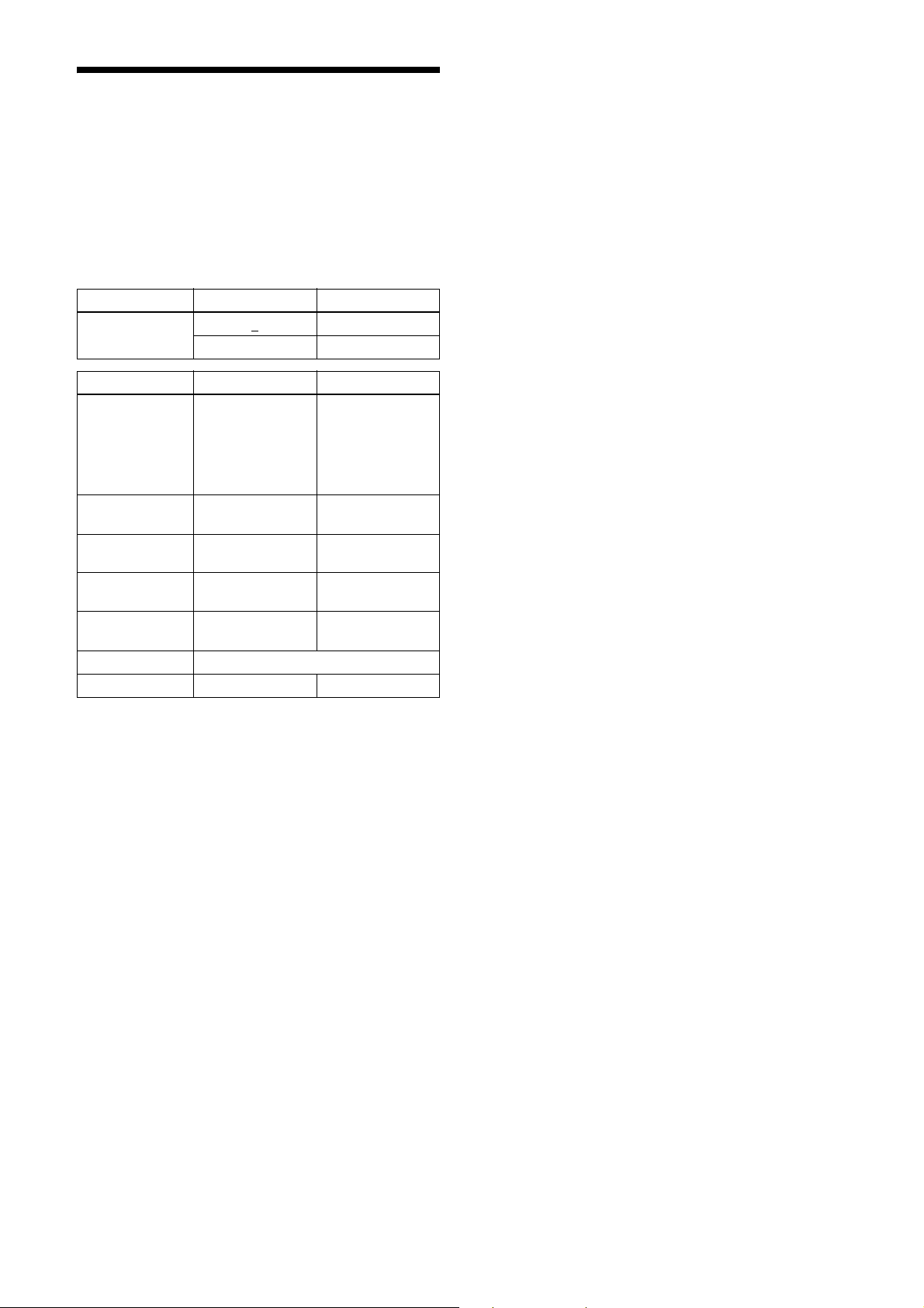
Drive mode
“Mode 0” which prioritizes the frame rate is set by
default.
The frame rate upper limit of “Mode 0” is higher
than“Mode 1,” but the usable functions are limited.
When correcting the defects/shadings in “Mode 0.”
After detecting and saving the defects/shadings in
“Mode 1,” return to “Mode 0” and use them.
Reboot the unit to reflect the changes of the drive mode.
command parameter Setting
DRIVE_MODE 0
1Mode 1
DRIVE_MODE Mode 0 Mode 1
Maximum frame
rate
Defect detection
function
Defect correction
function
Shading detection
function
Shading correction
function
Output format See the “Output format” function.
Free set sequence z –
75 fps (XCGCG160/CG160C)
41 fps (XCGCG240/CG240C)
23 fps (XCGCG510/CG510C)
– z
zz
– z
zz
Mode 0
50 fps (XCGCG160/CG160C)
32 fps (XCGCG240/CG240C)
15 fps (XCGCG510/CG510C)
z Usable function – Not usable function
16
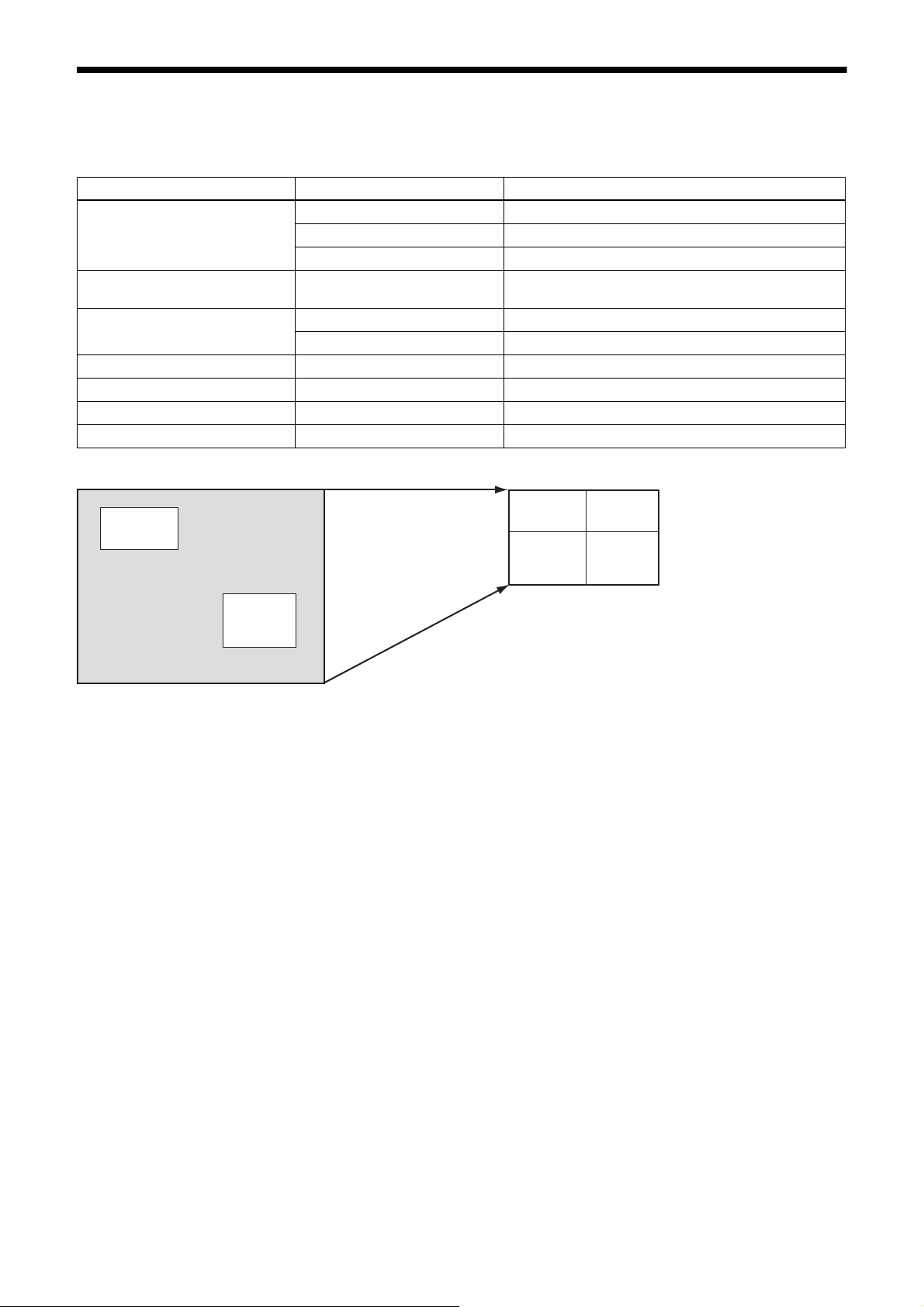
Multi ROI (XCG-CG160/CG160C only)
Af
You can set and read two arbitrary rectangular areas from the effective pixel area.
By reading only necessary parts, you can shorten the time it takes to read.
Register Parameter Setting
MultiROIMode 0 (Off) All areas Off
1 (On) All areas On
2 Highlight
MultiROISelect 0 to 1 Designates the number of the area the parameter is to be
changed.
MultiROIEnable 0 (Off) The area designated in MultiROISelect is Off.
1 (On) The area designated in MultiROISelect is On.
MultiROIWidth 4 to 1456 Horizontal size of the area
MultiROIHeight 4 to 1088 Vertical size of the area
MultiROIOffsetX 0 to 1452 Horizontal position of the area
MultiROIOffsetY 0 to 1084 Vertical position of the area
Before reading the part
䋰
ter reading the part
䋰
䋱
䋱
17

Output format
The settable pixel formats are as follows:
Register Model Drive mode ReverseX/Y Parameter Setting
PixelFormat XCG-CG240 Mode0 * 0x01080001 Mono8
* 0x010C0004 Mono10Packed
Mode1 * 0x01080001 Mono8
* 0x010C0004 Mono10Packed
* 0x010C0006 Mono12Packed
XCG-CG240C Mode0 0 0x0108000B BayerBG8
0 0x010C0029 BayerBG10Packed
Mode1 0 0x0108000B BayerBG8
0 0x010C0029 BayerBG10Packed
0 0x010C002D BayerBG12Packed
Mode0 1 0x01080008 BayerGR8
1 0x010C0026 BayerGR10Packed
Mode1 1 0x01080008 BayerGR8
1 0x010C0026 BayerGR10Packed
1 0x010C002A BayerGR12Packed
Mode0 2 0x0108000A BayerGB8
2 0x010C0028 BayerGB10Packed
Mode1 2 0x0108000A BayerGB8
2 0x010C0028 BayerGB10Packed
2 0x010C002C BayerGB12Packed
Mode0 3 0x01080009 BayerRG8
3 0x010C0027 BayerRG10Packed
Mode1 3 0x01080009 BayerRG8
3 0x010C0027 BayerRG10Packed
3 0x010C002B BayerRG12Packed
* 0x02180014 RGB8Packed
* 0x02180015 BGR8Packed
* 0x02180020 YUV8_UYV(YUV444)
* 0x0210001F YUV422_8_UYVY
* 0x02100032 YUV422_8
XCG-CG160/
CG510
Mode0 * 0x01080001 Mono8
Mode1 * 0x01080001 Mono8
* 0x010C0004 Mono10Packed
* 0x010C0006 Mono12Packed
*: optional
* Selectable setting format varies between drive modes.
* Modes for ReverseX/Y are limited for the color camera, as some setting formats fix the pixel array.
18
 Loading...