

Sony XCG-C30, XCG-C32, XCG-C130, XCG-C30C, XCG-C32C Technical Manual
...
Digital Video
Camera Module
C-189-100-11 (1)
Technical Manual
XCG-C30/C32/C130
XCG-C30C/C32C/C130C
© 2015 Sony Corporation

Table of Contents
Overview
Features .................................................................. 3
Typical CCD Phenomena ...................................... 4
System Components .............................................. 5
Connection ............................................................. 6
Location and Function of Parts and
Operation ............................................................... 7
Front/Top/Bottom ............................................... 7
Using a tripod ..................................................... 7
Rear .................................................................... 8
Connecting the cables ........................................ 9
Controlling the camera from the host device ..... 9
When mounting the camera ............................. 10
Heat dissipation of the camera ......................... 11
The electrolytic capacitor during the PoE
operation ......................................................... 11
Connections
Network Settings ................................................. 12
Using Persistent IP ........................................... 12
Using DHCP .................................................... 12
Using LLA ....................................................... 12
Packet Size ....................................................... 12
Packet Delay ..................................................... 12
Network connection speed .................................. 13
Trigger Signal Input ............................................ 14
Trigger signal polarity ...................................... 14
GPIO Connector .................................................. 15
Frame Rate ...........................................................25
Auto frame rate .................................................25
Specifying frame rate ........................................25
Displaying frame rate .......................................25
Fastest frame rate for partial scanning ..............26
Timing Chart ........................................................28
Trigger latency ..................................................28
Sensor Readout (Sensor Output) ........................29
White Balance ......................................................30
LUT .......................................................................30
Binarization ......................................................30
5-point interpolation .........................................30
Arbitrary setting ................................................31
Save LUT ..........................................................31
Color Matrix Conversion ....................................31
3 × 3 filter ..............................................................32
Test Chart Output ................................................32
GPIO .....................................................................33
GPI ....................................................................33
GPO ..................................................................33
Pulse Train Generator .........................................35
Status LED ............................................................35
Temperature Readout Function .........................35
Sensitivity Control ...............................................35
User Set .................................................................35
User set memory ...............................................35
User ID ..................................................................36
Saving and Startup ..............................................36
Camera Information ............................................36
Restart ...................................................................36
Switching a CCD Driving Clock .........................36
Command List ......................................................37
Functions
Partial Scan .......................................................... 16
Binning ................................................................. 16
Output format ...................................................... 17
Gain ...................................................................... 17
Analog gain ...................................................... 17
Auto gain (AGC) .............................................. 17
Shutter (Exposure) .............................................. 18
Configuring the setting ..................................... 18
Auto exposure (AE) ......................................... 18
Combination of Continuous AGC and Continuous
AE ......................................................................... 18
Trigger Control .................................................... 19
Free run/trigger mode ....................................... 19
Special trigger .................................................. 20
Trigger source .................................................. 21
Trigger inhibition ............................................. 21
Trigger shift ...................................................... 22
Trigger delay .................................................... 23
Trigger counter ................................................. 23
Trigger range limit ........................................... 23
Trigger control .................................................. 24
Specifications
Specifications ........................................................45
Spectral Sensitivity Characteristics (Typical
Values) ...................................................................46
Dimensions ............................................................48
2
Table of Contents

Overview
Before operating the unit, please read this manual
thoroughly and retain for future reference.
Partial scan (during DC IN power supply
only)
The camera module can limit the number of video
output lines to achieve high frame rates, enabling highspeed image processing.
Overview
This unit is a digital video camera module that adopts
the 1000BASE-T/100BASE-TX interface.
Features
GigE Vision compliant
This unit supports GigE Vision Ver.2.0/Ver.1.2, and the
versions are switchable by changing the settings.
High image quality
All cameras feature a progressive scan CCD for highresolution images. Both cameras produce stable output
images, by adopting the proven CCD.
By adopting square pixels, images can be processed
using the original aspect ratio without a converting
procedure.
The following models and their CCDs are shown below.
Model name Pixel count
XCG-C30/C32/C30C/
C32C
XCG-C130/C130C 1,300,000-pixel CCD,
330,000-pixel CCD, compatible
with VGA
compatible with SXGA
Body fixing
The screw holes to install the camera module are located
under the front panel (the CCD reference plane).
Installing the camera module on the front panel
minimizes deviation of the optical axis.
LUT (Look Up Table)
You can switch to OFF or ON. When set to ON, you can
select from five preset values, such as inversion,
binarization, settable five-point approximations, etc.
Switching an Output Bit Length
You can select 8-bit output, 10-bit output, or 12-bit
output.
For color models, you can also select an output of RGB
24-bit, YUV 24-bit, or YUV 16-bit.
Binning (during DC IN power supply/
black and white camera only)
Sensitivity can be doubled by combining two pixels
aligned vertically, you can achieve a standard output
frame rate between 1.8x and 2x. Sensitivity can be
doubled by combining two pixels align horizontally.
You can set horizontal and vertical binning at the same
time.
Various settings
Sending a command from the host device allows various
settings, including the following.
•Gain
•Shutter
• Partial scan (during DC IN power supply only)
• Trigger control
• LUT (Look Up Table)
• Output: 8/10/12-bit, RGB 24-bit, YUV 24-bit
(YUV444), or YUV 16-bit (YUV422)
Electronic shutter function
Set anywhere from 1/100,000 sec to 2 sec in 1 µs
increments. If you do not prioritize the image quality,
you can set it up to 60 sec during operation.
External trigger shutter function
By synchronizing with an external trigger signal, any
shutter timing can be used.
White balance control (color camera
only)
You can adjust the R and B level against G level to adjust
the white balance. This unit is also equipped with the
one-push white balance function, by which the camera
can automatically adjust the white balance.
Note
The CCD is driven at high speed during a Partial scan or
Binning operation. In this situation, if intense light is
input to the camera, the peripheral areas of the video
image may be affected. In such a situation, adjust the
amout of light using the iris.
Features
3

CCD used in XCG-C130/C130C
Typical CCD Phenomena
The following effects on the monitor screen are
Overview
characteristic of CCD cameras. They do not indicate any
fault with the camera module.
Smear
This occurs when shooting a very bright object such as
electric lighting, the sun, or a strong reflection.
This phenomenon is caused by an electric charge
induced by infrared radiation deep in the photosensor. It
appears as a vertical smear, since the CCD imaging
element uses an interline transfer system.
Vertical aliasing
When you shoot vertical stripes or lines, they may
appear jagged.
Under the following operating conditions, because the
construction of the CCD of this camera is different from
the CCDs used in other cameras, the brightness level
near the pedestal may increase, or white dots described
above may become pronounced, degrading the image
quality.
• When used in a hot environment
• When the gain is increased
• When the exposure time is long (0.1 second or longer)
In these situations, decrease the environmental
temperature, or adjust the light source or lens aperture,
and change the camera gain or exposure time.
Note on laser beams
Laser beams may damage a CCD. You are cautioned
that the surface of a CCD should not be exposed to
laser beam radiation in an environment where a laser
beam device is used.
Blemishes
A CCD image sensor consists of an array of individual
sensor elements (pixels). A malfunctioning sensor
element will cause a single pixel blemish in the picture
(This is generally not a problem.).
White speckles
While CCD image pickup device is made by an accurate
technique, imperceptible speckless may rarely come up
on the screen due to cosmic rays and so on. This is
connected to the principle of CCD image pickup device,
not a malfunction. And the white speckless are easy to
come up in the following conditions.
• Using the camera in high temperature
• When turning up the gain
Note
If strong light enters a wide area of the screen, the screen
may become dark. This is not a malfunction.
If this occurs, avoid strong light or adjust the lens iris to
reduce the light amount.
4
Typical CCD Phenomena
System Components
a
cd e
fg
b
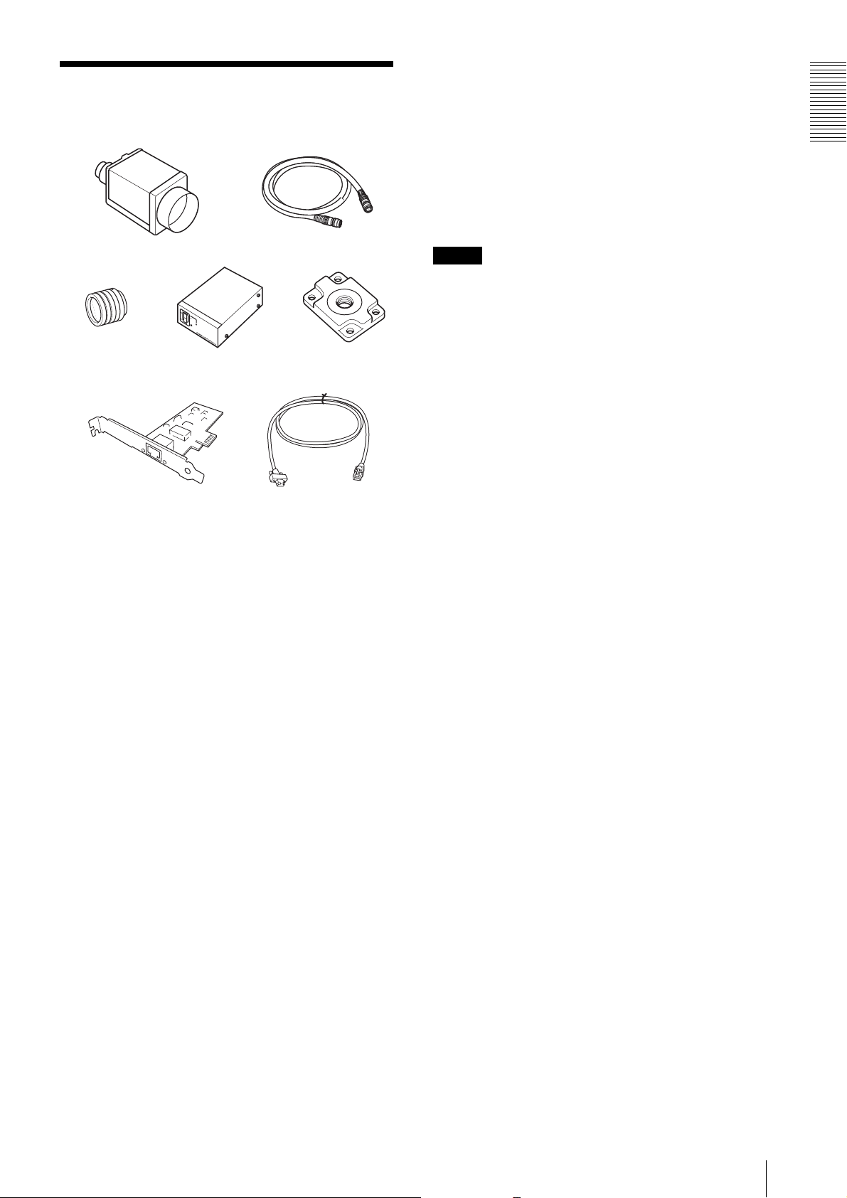
g LAN cable
This cable connects to the RJ45 connector on the rear
panel of the camera module.
Image/control signals are transmitted via this cable. Use
a LAN cable (CAT5e or higher standard) that supports
1000BASE-T (or allows 100BASE-TX when it is used).
Depending on the attributes of the LAN cable, images
may become less clear and the camera module may
become unstable. Be sure to use a LAN cable that has
sufficient noise reduction.
Note
When you connect the LAN cable of the unit to
peripheral device, use a shielded-type cable to prevent
malfunction due to radiation noise.
Overview
The video camera module system comprises the
following optional products (available separately).
a Video Camera Module
This is a small-size, high image-quality video camera
module that uses a progressive scan CCD image sensor.
b Camera cable
This is attached to the DC IN connector of the camera
module and is used for power supply and exchange of
trigger signals.
For purchasing the cable, consult the dealer.
c C-mount lens
Use a suitable lens to fit the camera pixel count.
d DC-700/700CE camera adaptor
This is connected to the camera module to enable power
supply from ordinary AC power source.
e VCT-333I tripod adaptor
This attaches to the bottom of the camera module to fix
the camera module to a tripod.
f Camera module interface board (Network
interface card)
Install the board in the expansion slot of the host device
(ex: computer). Use a board that is appropriate for your
system and that supports 1000BASE-T (or allows
100BASE-TX when it is used) and jumbo packets.
System Components
5
Connection
Overview
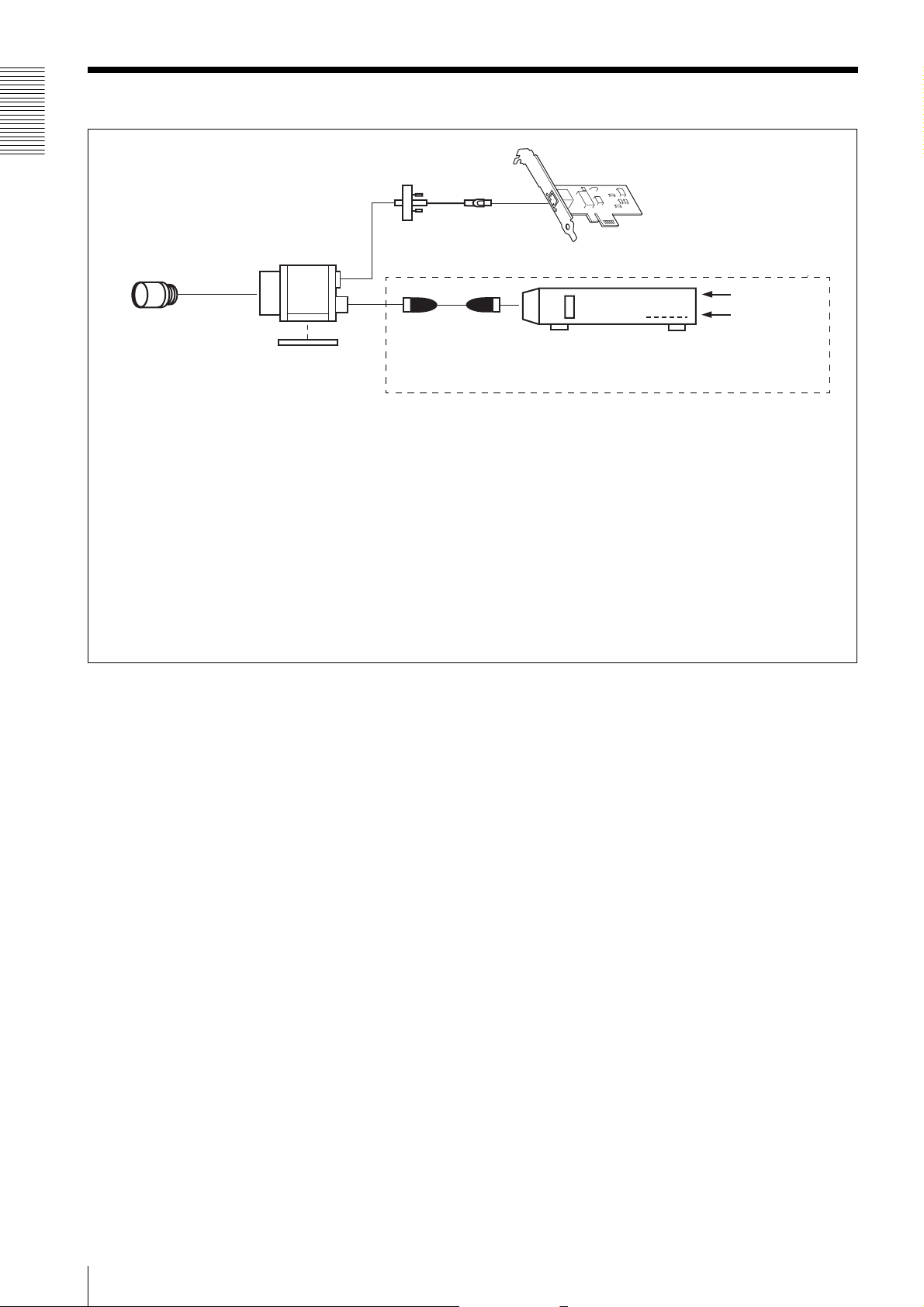
LAN cable
Camera module
C-mount lens
Camera cable
Tripod adaptor
VCT-333I
If the HUB supports PoE, the items within the dashed line are not necessary.
Power supply
You can supply power to the camera module using the following methods.
Using the RJ45 connector
This unit supports PoE (IEEE802.3af standard). By using a PoE-compatible LAN cable and camera module interface board or hub,
you can power, control, and output images from the camera using one LAN cable.
When you operate this unit using PoE, heat dissipation is required depending on the usage environment because the inside of the
camera becomes hot.
For heat dissipation, refer to the User's Guide.
Camera module interface board
AC
TRIG
Camera adaptor
DC-700/700CE
(adopt EIAJ compliant 12-pin
connector pin assignments)
Using the DC IN connector
You can supply power via the DC IN connector using the power adapter.
Use DC-700/700CE which is the stable power source free from ripple or noise.
6
Connection
Location and Function of Parts and Operation
Front/Top/Bottom
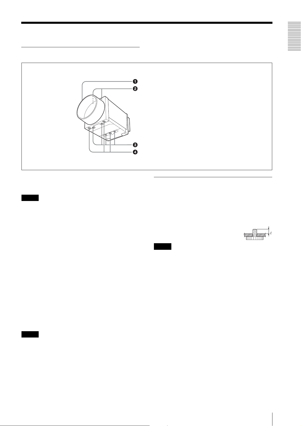
a Lens mount (C-mount)
Attach any C-mount lens or other optical equipment.
Note
The lens must not project more than 10 mm (13/32 inch)
from the lens mount.
When you use the camera with the lens attached, the
resolution of the image output from the camera may
differ according to the performance of the lens. Note it
when you select a lens.
The performance of a lens may change according to the
aperture level.
If the resolution is not enough, adjust the aperture level.
b Guide screw holes (Top)
Overview
Lens mount (C-mount)
Guide screw holes (Top)
Guide screw holes/Tripod screw holes (bottom)
Reference screw holes (bottom)
Using a tripod
To use the tripod, install the tripod adaptor VCT-333I
(not supplied) on the camera module.
Use a tripod screw with a protrusion (4) extending from
the installation surface, as follows, and tighten it, using
a screwdriver. Be sure that the protrusion (4) does not
exceed 5.5 mm (0.2 in.) in length.
Length 4.5 to 5.5 mm
Length 0.18 to 0.22 inches
Note
If you install a tripod adapter (not supplied), use the
screws provided.
c Guide screw holes/Tripod screw holes (bottom)
When using a tripod, use these four screw holes to attach
a VCT-333I tripod adaptor.
d Reference screw holes (bottom)
These precision screw holes are for locking the camera
module. Locking the camera module into these holes
secures the optical axis alignment.
Note
Refer to XCG-C30 Demensions in page 48 for about the
position/size of the Guide hole and the Reference hole.
Location and Function of Parts and Operation
7
Rear
Overview
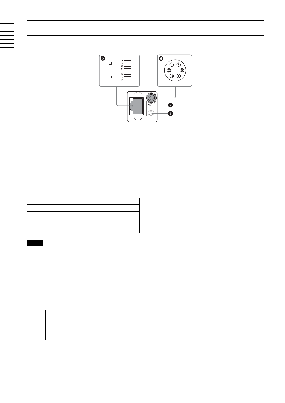
e RJ45 connector
You can connect a LAN cable to this connector to
control the camera module from a host device to output
image to a host device. By using a PoE-compatible LAN
cable and camera module interface board or hub, you
can supply power using the LAN cable.
(Refer to Fig.
5 above for the pin assignment of the
connector.)
Pin No. Signal Pin No. Signal
1TP3 + 5TP1 –
2TP3 – 6TP2 –
3TP2 + 7TP4 +
4TP1 + 8TP4 –
Note
For safety, do not connect the connector for peripheral
device wiring that might have excessive voltage to this
port. Follow the instructions for this port.
f DC IN (DC power input) connector (6-pin)
You can connect a camera cable to input the +12 V DC
power supply. The pin configuration of this connector is
as follows.
(Refer to Fig.
6 above for the pin assignment of the
connector.)
g Reset switch
This reformats the network settings.
h Status LED (Green)
When power is on, this LED lights up.
Pin No. Signal Pin No. Signal
1 DC input (10.5 V
to 15 V)
2 GPI1 (ISO +) 5 GPI1 (ISO –)
3 GPI2/GPO2 6 GND
8
Location and Function of Parts and Operation
4 GPI3/GPO3
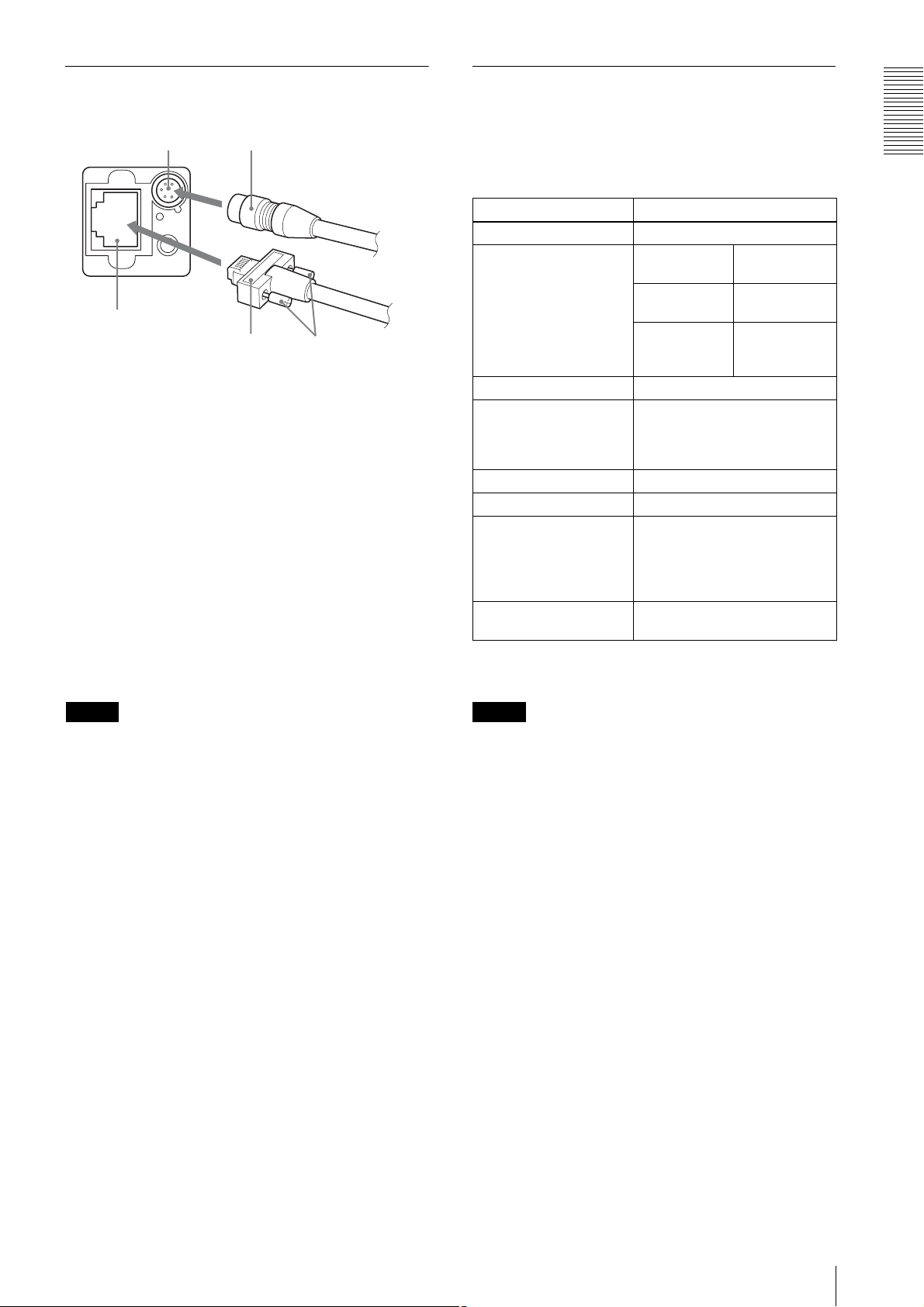
Connecting the cables
Controlling the camera from the host device
Connect the camera cable to the DC IN connector and
connect the LAN cable to the RJ45 connector
respectively. If you use a camera module interface board
or a hub with support for PoE, you can operate the
camera even if you do not connect the camera cable to
the DC IN connector. When you connect the LAN cable
with fastening screws, turn the two screws on the
connector to secure the cable tightly.
1 DC IN connector 2 RJ45 connector
3 Camera cable 4 LAN cable
5 Fastening screws
Connect the other end of the camera cable to the DC700/700CE and the other end of the LAN cable to the
camera module interface board or a hub.
You can control the camera from host devices such as a
computer. The following table shows the major control
functions.
Control functions Description
Operating mode Free run/Trigger
Shutter speed* Free run 1/100,000 sec to
2 sec
Trigger edge
detection
Trigger pulse
width detection
Gain 0 dB to 18 dB
Partial Scan (during DC
IN power supply only)
LUT (Look Up Table) OFF/ON (Mode: 5 types)
External trigger input DC IN connector
Video output switch Monochrome model: Mono 8/10/
Binning (during DC IN
power supply only)
Variable, 2-line increments (the
number of settable lines is 32 or
more/the recommended setting is
120 lines or more)
12-bit
Color model: Raw 8/10/12-bit,
RGB 24-bit, YUV 24-bit, YUV
16-bit
2×1, 1×2, 2×2
1/100,000 sec t o
2 sec
Setting by
trigger pulse
width
*If you do not prioritize the image quality, you can set
the shutter speed up to 60 sec during operation.
Overview
Note
Do not supply power to the camera cable and LAN cable
at the same time.
Note
Make sure to supply power to the camera module and
confirm that the camera module is operating before
inputting a trigger signal. If you input trigger signal to a
camera module without the power supplied, this may
cause a malfunction of the camera module.
Do not exit the application software of the host device
before completing the image transmission from the
camera. This may cause a malfunction on the camera.
Location and Function of Parts and Operation
9
When mounting the camera
When you operate this unit in the following conditions,
heat dissipation is required depending on the usage
Overview
environment because the inside of the camera becomes
hot.
• when using PoE system
• when the partial scan is set to less than 120 lines
during the power is supplied through DC IN
To promote heat dissipation from the unit and maintain
performance, mount the camera to a metallic heat
dissipation plate.
Dimension of the heat dissipation plate: 180 mm ×
110 mm × 5 mm or more (Thermal conductivity:
16.3 W/m·K or more)
For heat dissipation, refer to the User's Guide.
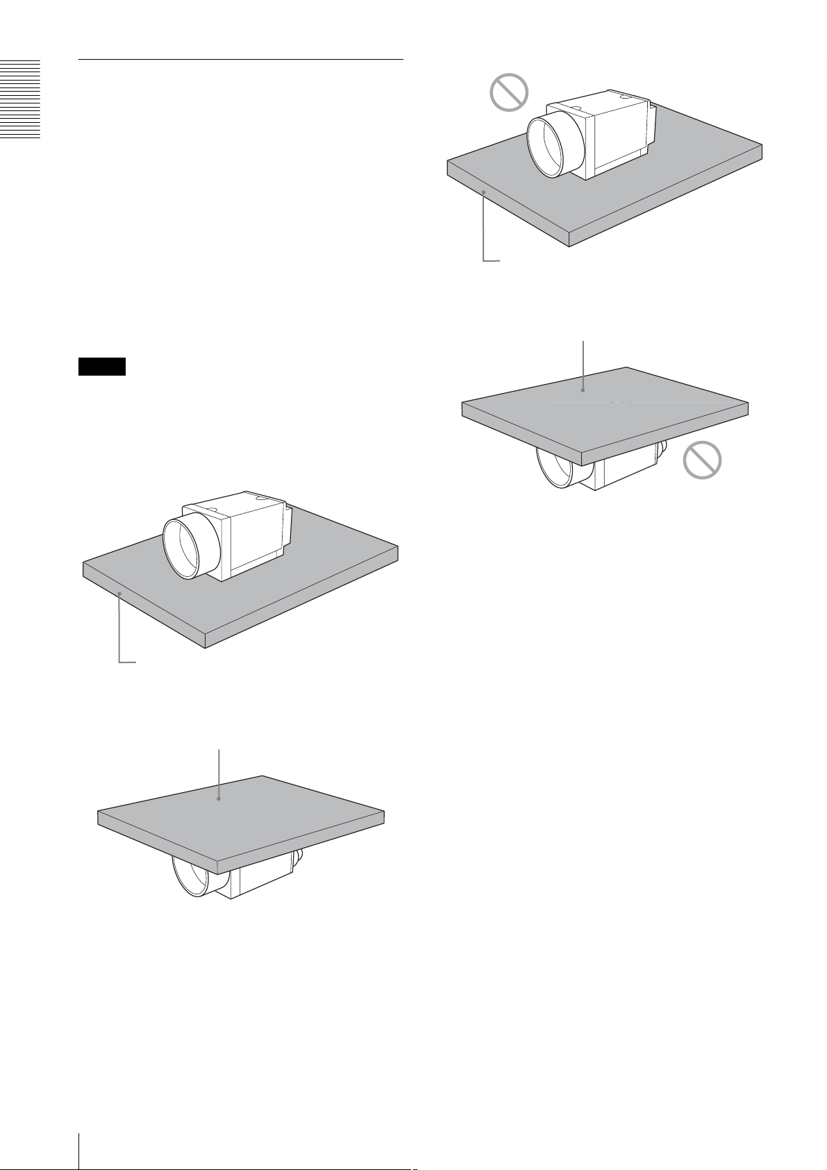
Notes
• When mounting the camera to the heat dissipation
plate, secure the camera tightly by using the reference
screw holes (see page 7) and screws.
• Do not mount the camera to a plate made of a material
such as wood or resin that prevents heat dissipation.
Plate that prevents heat dissipation
(made of wood, resin, etc.)
Plate that prevents heat dissipation
(made of wood, resin, etc.)
Metallic heat dissipation plate
Metallic heat dissipation plate
10
Location and Function of Parts and Operation
Heat dissipation of the camera
The electrolytic capacitor during
• Use this camera in an environment that the read value
of the temperature sensor is 68°C (154.4°F) or less
during PoE mode.
• The read value of the temperature sensor becomes
high if the temperature around the camera is high.
When the read value is higher than 68°C (154.4°F),
mount a heat dissipation plate to the camera.
• If you use a larger heat dissipation plate, it is possible
to lower the read value of the temperature sensor.
The read value of the temperature sensor can be
obtained by the following formula:
Read value of temperature sensor =
Temperature around the camera + Temperature inside
the camera
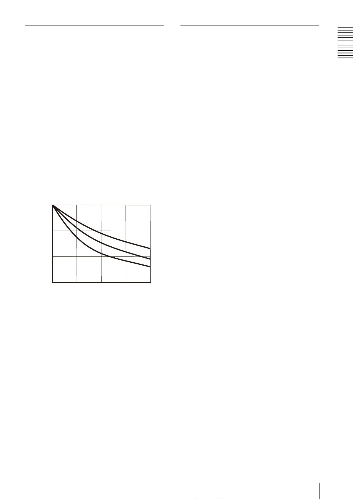
The relation between the heat dissipation plate area
and the temperature inside the camera is shown in the
following graph:
(The heat dissipation differs depending on the
material.)
35/95
the PoE operation
This unit has an electrolytic capacitor.
This electrolytic capacitor is not powered on during the
DC IN operation. It is powered on during the PoE
operation.
When the power is supplied by PoE, the electrolytic
capacitor is designed to work for more than 3 years
without any problems even if it is operated for 24 hours
under an environment at a temperature of 40°C (104°F).
Also, if the operating time is 8 hours per day, the life
expectancy is 3 times the above mentioned period.
Periodic inspections are recommended if it is used for a
long time.
◆ Contact a Sony sales representative for more
information about inspections.
Overview
30/86
SUS
25/77
Temperature inside the camera (˚C/˚F)
20/68
0
Heat dissipation plate area (cm2) *Thickness: 0.5 cm (7/32 inches)
50 100 150
Fe
Al
200
Location and Function of Parts and Operation
11

Connections
Connections
Network Settings
For the camera to be connected to a network, the
following address data must be properly specified:
• IP address
• Subnet mask
• Default gateway
The camera provides the following three methods for the
address data setting:
• Using Persistent IP
• Using DHCP
• Using Link Local Address (LLA)
Using Persistent IP
Use this method when the IP address to be assigned to
the camera has been specified in advance. When using
the persistent IP, subnet mask and default gateway
settings are also required. When using persistent IP
forwarding on a router, default gateway settings are also
required.
Packet Delay
The delay amount to be inserted between packets can be
set when sending them to a network. By increasing the
packet delay, you can reduce the network bandwidth that
the camera uses for sending packets. However, as the
amount of data sent in a certain time is decreased with
increased delay, the frame rate of output images of the
camera may be consequently decreased.
Using DHCP
The camera is equipped with a function to automatically
obtain an IP address by communicating with a DHCP
server on a network. When using the DHCP method for
IP address setting, the subnet mask and default gateway
values automatically obtained from the DHCP server are
also used.
Using LLA
If neither Persistent IP nor DHCP is used, or if an IP
address cannot be obtained from the DHCP server, the
IP address is determined by LLA. The IP address
determined by LLA will be 169.254.XXX.YYY, with
XXX and YYY automatically specified.
In addition, the following network settings can be
changed.
• Packet size
• Packet delay
Packet Size
The amount of image data per packet can be set in bytes.
To permit the camera to operate properly, set the packet
size to a value less than the MTU of the network device
connected to the camera. Set the largest value in the
networks including the hub.
12
Network Settings
Network connection speed
This unit supports the connection with 1000Base-T
(1 Gbps) or 100Base-TX (100 Mbps).
When you connect the unit to the network, negotiate the
communication speed with the connected equipment
and start communication at a higher speed of that both
equipment are compatible with.
When using the unit with 100Base-TX connection, the
frame rate to be output is limited, because the output
data band width from the camera becomes narrow
compared to the 1000Base-T connection.
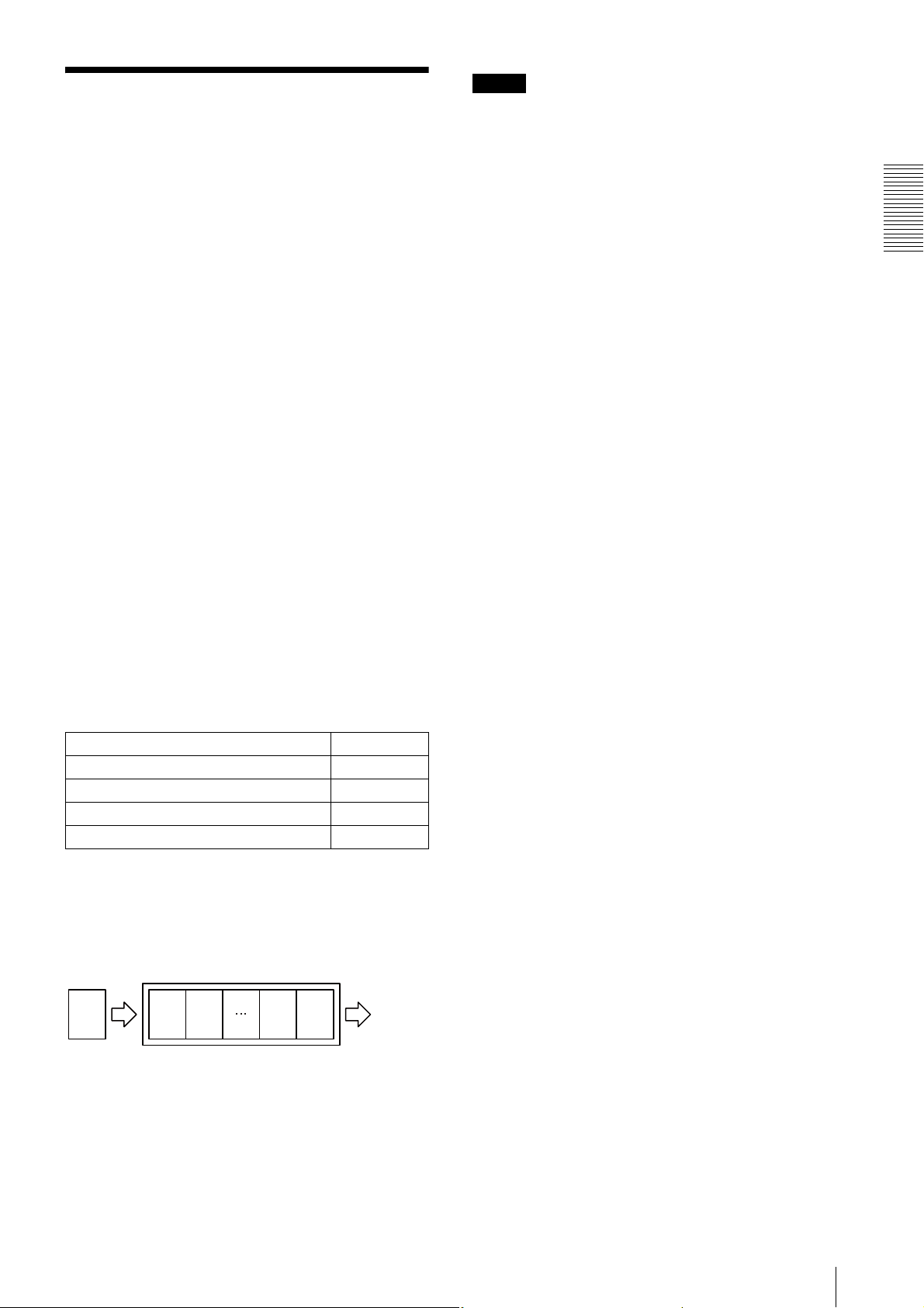
The camera has a buffer to store multiple images and all
of the shot images are stored once in the buffer.
The stored images are output from the camera in order
starting from the oldest image in the buffer.
Therefore, if the frame rate during shooting is faster than
the frame rate that can be output from the camera, the
image data will always be stored in the buffer, and the
time interval from shooting to image output becomes
large.
To avoid this situation, it is required to set the shooting
frame rate to the proper value when using 100Base-TX
connection.
The data rate of images is obtained by the following
formula:
Notes
• Any persistent IP address can be entered, but the
camera may become unable to be detected, depending
on the IP address setting. If this occurs, use a tool for
issuing ForceIP and set a persistent IP address again.
• When setting the parameters (Width, Height, and
PixelFormat) for calculating the payload size, stop
camera image output beforehand.
Connections
Data rate = Width
× Height × BPP × FPS
Width: Width of image
Height: Height of image
BPP: The number of bits per pixel depends on the
PixelFormat setting
Mono8/BayerRG8 8-bit
Mono10Packed/BayerRG10Packed 12-bit
Mono12Packed/BayerRG12Packed 12-bit
RGB8Packed/BRG8Packed/YUV8_UYV 24-bit
YUV422_8/YUV422_8_UYVY 16-bit
FPS: Frame rate [frame/sec]
It is possible to minimize delay by using the camera at a
frame rate where the data rate becomes low with a
margin against 100 Mbps.
Buffer
CCD
Image nImage
n
Image 2Image
1
Image
output
Network connection speed
13
Connections
Trigger Signal Input
Trigger signals can be input via the 2nd, 3rd, 4th pins of the DC IN connector, or the software command. Switchover of
the trigger signal can be changed via the TriggerSource register.
Register Parameter Setting
TriggerSource Line1 (0)
Line2 (1) DC IN connector 3rd pin (GPI2) *
Line3 (2) DC IN connector 4th pin (GPI3) *
Software (4) Software (TriggerSoftware register)
* The 3rd and 4th pins of DC IN connector are available only when the input/output switching setting is set to input.
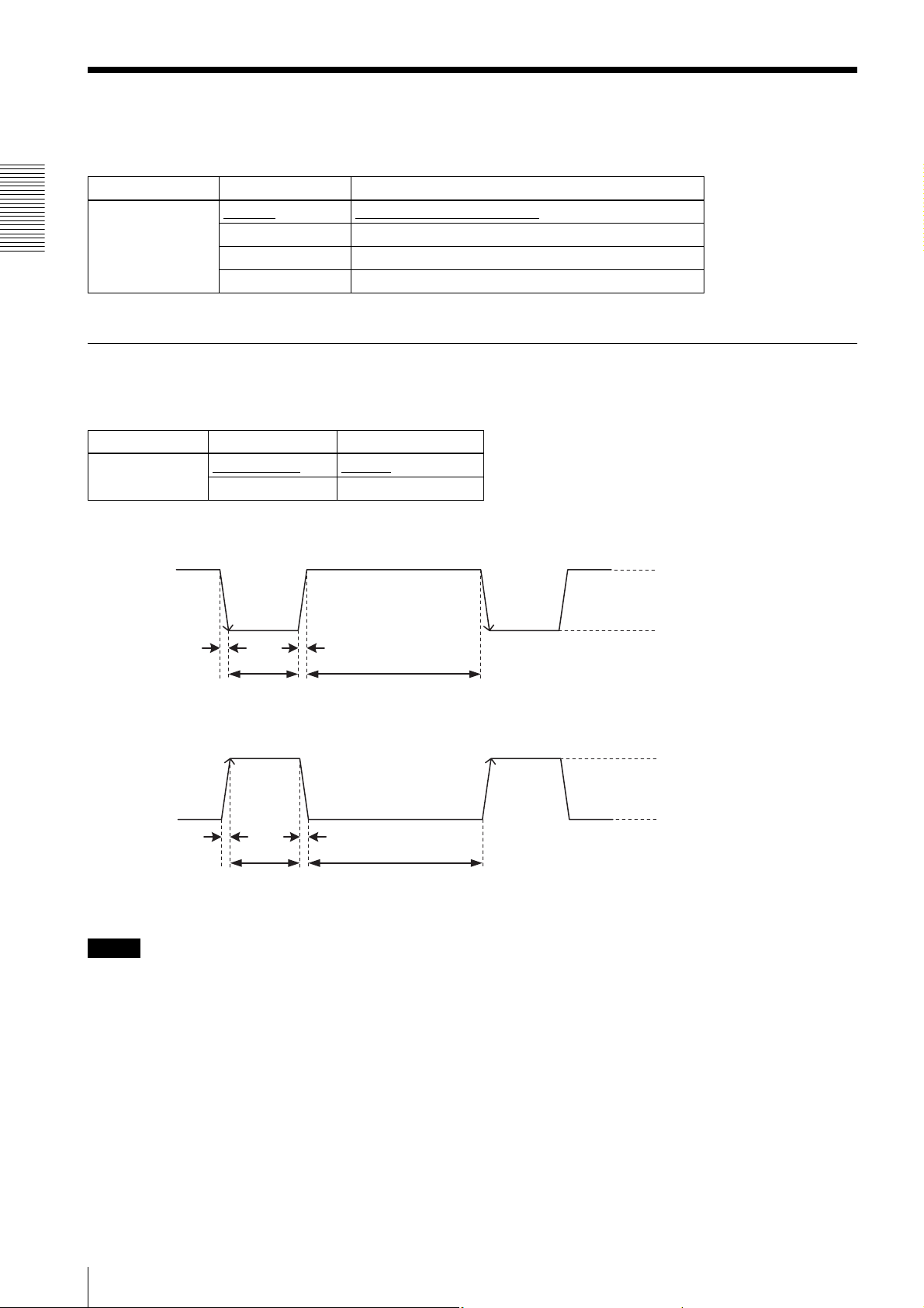
Trigger signal polarity
Positive refers to a trigger signal polarity activated while rising from Low to Hi, or during the Hi interval. Negative refers
to a trigger signal polarity activated while falling from Hi to Low, or during the Low interval.
Register Parameter Setting
TriggerActivation FallingEdge (0)
RisingEdge (1) Positive
DC IN connector specifications
DC IN connector 2nd pin (GPI1)
Negative
5 to 24 V (DC IN connector 2nd pin)
3.5 to 5.5 V (DC IN connector 3rd
and 4th pins)
0 to 0.4V
2.0µs or less
10µs to 2s
2.0µs or less
100µs or more
Trigger input polarity = Negative
5 to 24 V (DC IN connector 2nd pin)
3.5 to 5.5 V (DC IN connector 3rd
and 4th pins)
0 to 0.4V
2.0µs or less
10µs to 2s
2.0µs or less
100µs or more
Trigger input polarity = Positive
Note
When inputting a trigger signal to the camera using the DC-700/CE, use DC 5 V or less at the logical high level.
14
Trigger Signal Input

GPIO Connector
The 2nd DC IN connector is the GPI connector and the 3rd and 4th are connectors that can set to either GPI or GPO.
The trigger reset pin is the DC IN connector 2nd pin (GPI1). If you are connecting an external device to the GPI or GPO
connector, refer to the circuit specifications below.
GPI circuit specifications
5V
HCPL-M611
GPIO circuit specifications
GPI2/GPO2
180
MMBF4393LT1G
DC IN connector
DA2710100L
DC IN connector
#3
Connections
#2
#5
GPI3/GPO3
As GPI2/GPO2
#4
GPIO Connector
15
 Loading...