

Sony XCD-SX910CR, XCD-X710CR, XCD-SX710CR, XCD-SX910UV, XCD-SX910 User Manual
...
Digital Video
Camera Module
Technical Manual
A-BS3-100-13 (1)
XCD-SX910CR/X710CR (Color model)
XCD-SX910UV
XCD-SX910/X710
2003 Sony Corporation
(Ultraviolet-range model)
(Black and white model)

Table of Contents
Overview
Functions
Main Features ............................................................ 3
System Components................................................. 5
Connection Diagram ................................................. 6
Location of Parts and Operation.............................. 7
Brightness.................................................................. 8
Gain ............................................................................ 8
Shutter........................................................................ 8
Absolute Control V alue for the Shutter ....................... 9
Auto Exposure........................................................... 9
Trigger Shutter........................................................... 9
Pan/Tilt...................................................................... 10
Memory Channels ................................................... 10
Partial Scan.............................................................. 11
Binning Mode........................................................... 12
Format7 Mode3/4 for XCD-SX910CR/SX910UV/
SX910 ..................................................................... 12
Frame Rate Settings for Format 7.......................... 13
16-bit Mode .............................................................. 13
1394 Bus Synchronization...................................... 13
ExposureOut............................................................ 13
White Balance (XCD-SX910CR/X710CR only)....... 14
Hue (XCD-SX910CR/X710CR only) ........................ 14
Optical Filter (XCD-SX910CR/X710CR only) ......... 14
Control
Appendix
Camera Command Status Register ....................... 15
Memory Map ............................................................ 15
ConfigROM............................................................... 16
Control Base Address............................................. 18
Inquiring Supported Video Modes ......................... 18
Video Mode Settings ............................................... 20
Starting/Stopping Video T ransfer (ContinuousShot) ...
OneShot and MultiShot........................................... 20
Memory Channel Operation ................................... 21
Feature Controls...................................................... 22
Partial Scan Operation............................................ 26
Notes on the Camera Operations .......................... 29
Characteristics of the XCD-SX910UV .................... 31
Specifications .......................................................... 33
CCD Pixel Location (Top View)............................... 37
Spectral Sensitivity (Relative Response)
Parameters ............................................................ 38
Dimensions .............................................................. 40
20
XCD-SX910CR/X710CR
XCD-SX910UV
XCD-SX910/X710
2

The XCD-SX910CR/SX910UV/SX910 with its 1/2type PS IT CCD, and the XCD-X710CR/X710 with its
1/3-type PS IT CCD are high-resolution industrial-use
digital video camera modules. Utilizing an IEEE 13941995 digital interface, transfer rates as high as 400
Mbps are realized. In addition, the use of digital
signals enables industrial-use image processing
without “image deterioration,” an important plus in the
industrial world. Moreover, the use of a square pixel
CCD eliminates the need for aspect ration conversion
during image processing.
Finally, a vibration resistance feature permits use of
these units in all types of inspection and imaging
devices.
What is the IEEE1394?
The IEEE1394 is the standard serial bus for sending
and receiving digital data. It is prescribed as “IEEE*
Std. 1394-1995.”
The most outstanding feature of this interface is that it
realizes transfer speeds of up to 400 Mbps and can
handle large image data size. The interface is also
capable of “Isochronous transmission” which transmits
data real-time, for up to 64 channels. Connectors can
be inserted and disconnected while the unit is turned
on, and no terminators and no ID settings such as those
necessary for the SCSI interface are required.
* The Institute of Electrical and Electronics Engineers, Inc.
Overview
Overview
Main Features
The XCD-SX910CR/SX910UV/SX910 video
camera module utilizes a 1/2-type PS IT
CCD, and the XCD-X710CR/X710 utilizes a
1/3-type PS IT CCD
RAW mode output using the RGB Bayer
pattern (XCD-SX910CR/X710CR only)
High-speed digital interface IEEE1394
High-resolution
The XCD-SX910CR/SX910UV/SX910 adopts an
SXGA-compatible 1.45 M-pixel CCD while the XCDX710CR/X710 adopts an XGA-compatible 800 Kpixel
CCD to produce high-picture quality images.
External trigger function
The external trigger shutter function allows the image
exposure to be coordinated with external equipment
and moving objects.
For exposure time, the unit is equipped with Trigger
Mode 0, which indicates the length of the exposure
using the shutter parameter, and Trigger Mode 1,
which controls exposure time by the width of the
trigger signal.
It is also able to utilize a software trigger initiated by a
command from a program running on a host computer.
XCD-SX910CR/X710CR
XCD-SX910UV
XCD-SX910/X710
3

Partial scan output image format
It is equipped with a partial scan feature that divides an
entire screen image into 16 × 16 sections, allowing it
to be output as an optionally designated rectangle
within the required limits.
Use of this function enables frame rates faster than
normal speeds, thus enabling efficient image capture.
In addition, partial scan operations can be carried out
even without the input of an external trigger.
C-mount
High vibration-resistance structure
Binning
The unit is equipped with a Binning mode, which
increases the frame rate and increases the sensitivity
based on mixing the pixel data on the CCD imager.
The XCD-SX910UV/SX910 provides a screen size of
640 × 480, and on-screen movement at 30 fps is
available; the XCD-X710 provides a screen size of 512
× 384, and on-screen movement of 50 fps.
Overview
Black & white (Monochrome) 16-bit mode
A Black & white (Monochrome) 16-bit mode is
available. The bits used are the least significant
(lowest) 10 bits.
XCD-SX910CR/X710CR
XCD-SX910UV
XCD-SX910/X710
4
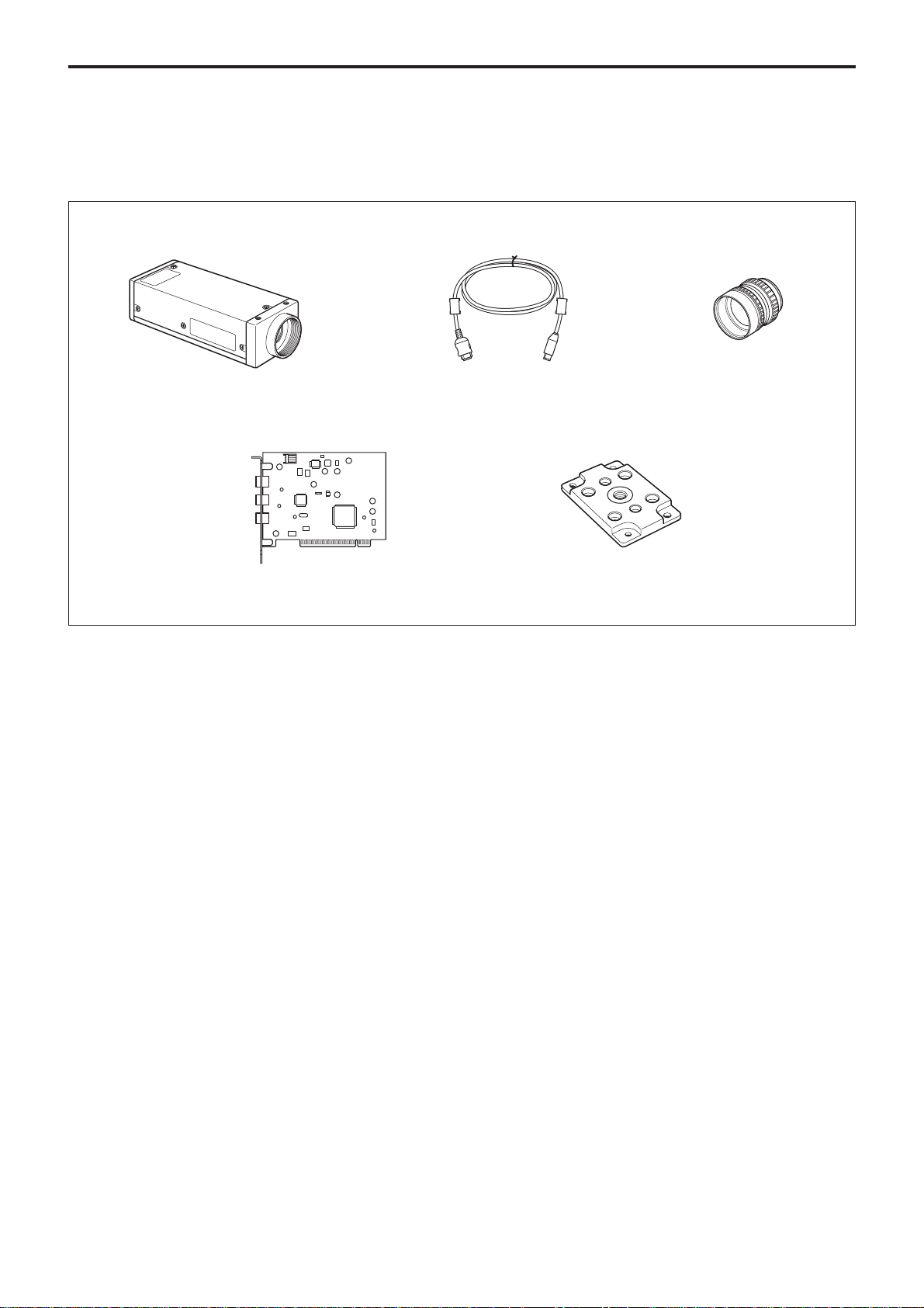
System Components
The XCD-SX910CR/SX910UV/SX910/X710CR/
X710 Video Camera Module system comprises the
following components.
Video Camera Module
XCD-SX910CR/SX910UV/SX910
XCD-X710CR/X710
IEEE1394 Cable
(6-pin, 4.5 m)
Overview
C-mount Lens
VF2509 (Canon)
Host Adapter Card
(Commercially available)
Tripod Adapter
VCT-ST70I (Isolated type)
XCD-SX910CR/X710CR
XCD-SX910UV
XCD-SX910/X710
5
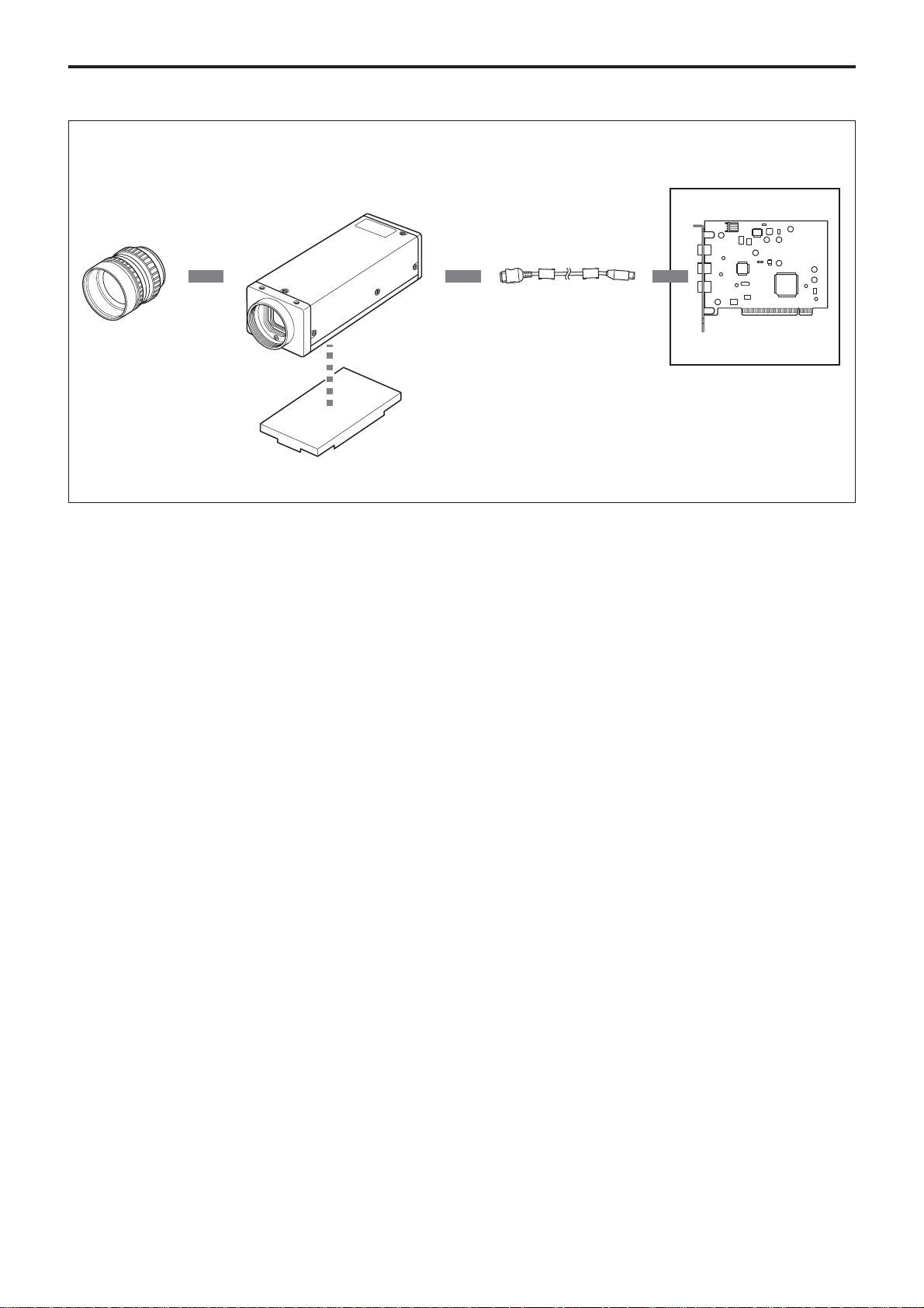
Connection Diagram
XCD-SX910CR/SX910UV/SX910
XCD-X710CR/X710
C-mount Lens
ita
ig
D
Overview
e
c
terfa
l In
IEEE1394 Cable
Recommended Lens: VF2509
(Canon)
Host Adapter Card
Host Equipment (PC, etc.)
Tripod Adapter
VCT-ST70I
XCD-SX910CR/X710CR
XCD-SX910UV
XCD-SX910/X710
6
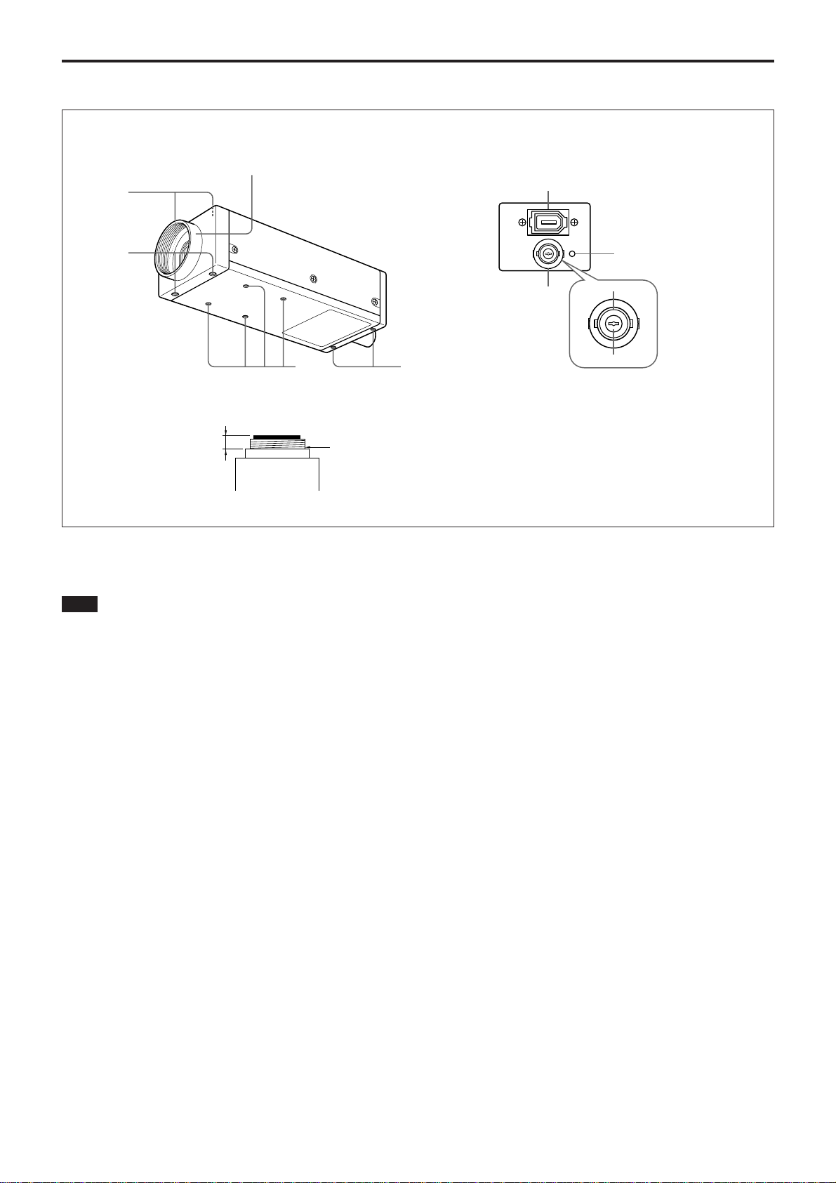
Location of Parts and Operation
Rear PanelFront/Top/Bottom
1
2
Overview
5
3
2
Digital Interface
1
1 Lens mount (C-mount)
Attach any C-mount lens or other optical equipment.
Note
The lens must not project more than 7 mm (9/32 inch)
from the lens mount.
1 Lens mount face 2 7 mm (9/32 inch) or less
2 Reference holes (Top)
3 Reference holes (Bottom)
These precision screw holes are for locking the camera
module. Locking the camera module into these holes
secures the optical axis alignment.
4 Tripod adaptor screw holes
Screw the tripod adaptor VCT-ST70I into the four
screw holes when you use a tripod.
TRIG IN
7
34
6
TRIG GND
TRIG IN
5 CAMERA connector
Connect the IEEE1394 camera cable (supplied) to this
connector.
6 Pilot lamp
This lamp indicates the camera module operation
states:
OFF: Camera power OFF
Green: Camera power ON/Video signal output OFF
Orange: Camera power ON/Video signal output ON
7 TRIG IN/Exposure OUT connector
Connect the trigger signal generator (trigger output
connector) to this connector.
When trigger is OFF, or software trigger is ON, a
signal that indicates the exposure time is output from
the BNC connector of the camera.
XCD-SX910CR/X710CR
XCD-SX910UV
XCD-SX910/X710
7
Brightness
This camera supports brightness control. This makes
fine adjustment of the black level possible. (The
former model, XCD-SX910/X710 (firmware version
1.07) does not support brightness control.)
Gain
Both Manual and Auto Gain setting are available with
this camera.
The variable range extends from 0 to 18 dB (XCDSX910CR/X710CR)/0 to 24 dB (XCD-SX910UV*/
SX910*/X710*), and the unit is designed so that the
gain can be subdivided and set to any of 640 steps.
At the factory default setting, the gain is set to 0 dB.
When Auto gain is selected, the gain is adjusted
automatically, based on the brightness of the subject.
At this time, the reference level (target point) is set in
the AutoExposure register.
Functions
Functions
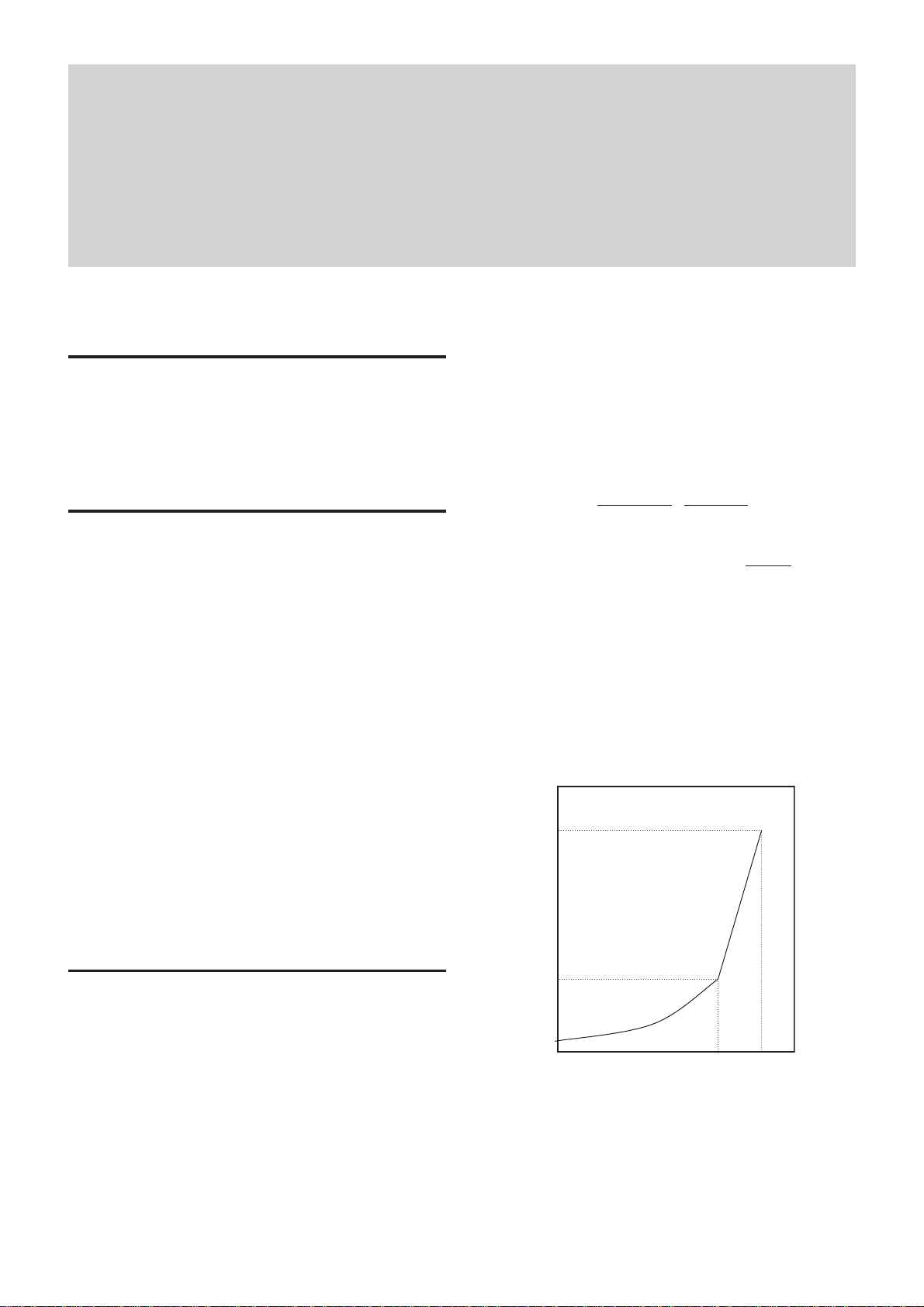
The relationship between the parameter and the
exposure time is given by the following formulas.
Where
P = Parameter (003h ~ 424h)
E = Exposure time (s)
P >= 3 ~ P <= 1000
2
E =
P > 1000 ~ P <= 1150
E = (P – 1000)*0.1 + 1
Setting examples
3 (003h) : 9
32 (020h) : 1 ms (1/1000)
100 (064h) : 10 ms (1/100)
1000 (3E8h) : 1 s
1010 (3F2h) : 2 s
1150 (47Eh) : 16 s
P
1000000
µ
s (1/100000)
1
2
For details on Auto Exposure, see page 9.
The XCD-SX910CR/SX910UV/SX910 and XCD-
X710CR/X710 are not compatible with the XCDSX900 and XCD-X700 in Gain settings.
*: If you set the gain to +18 dB or higher, the S/N ratio will
be severely degraded. Note this characteristic when you
use the XCD-SX910UV/SX910/X710.
Shutter
This camera allows both Manual and Auto Shutter
setting.
The variable range extends from 10 microseconds to
17.5 seconds; relative control values are indicated by a
12-bit integer, and absolute control values are
indicated using a 32-bit floating point value.
The shutter settings for the XCD-SX910CR/
SX910UV/SX910 and XCD-X710CR/X710 are the
same, but these settings differ from some of those for
the XCD-SX900 or XCD-X700.
XCD-SX910CR/X710CR
XCD-SX910UV
XCD-SX910/X710
16 s
2
1 s
1
10 µs
31000
When Auto Shutter is selected, the exposure time is
adjusted automatically, based on the brightness of the
subject. At this time, the reference level (target point)
is set in the AutoExposure register.
For details on Auto Exposure, see page 9.
1150
8
Functions
For long exposure times
When exposure times longer than the currently set
frame rate cycle are set, the camera enters the long
exposure time mode, and the actual frame rate is
slowed in accordance with the exposure time.
Absolute Control Value for the Shutter
Control of exposure time using absolute values is
possible. The values are indicated using a 32-bit
floating point value. (Unit: sec.)
The control steps are synchronized with the pixel
clock, and as the pixel clock is 30.5 MHz, one step is
approximately 32.8 ns.
The range for these values extends from 10
microseconds to 17.5 seconds.
Programming example;
union {
DWORD dwValue; // 1394 is expressed in quadlets,
float fValue; //
} AbsoluteShutterValue;
exposure time is indicated in seconds.
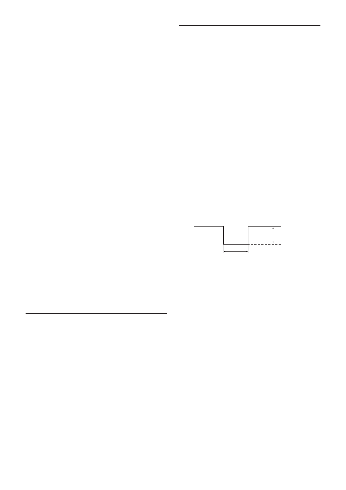
Trigger Shutter
Trigger shutter is useful for capturing images in
response to a trigger that starts the exposure to match a
preset timing. It can also be used to capture an image
using multiple cameras with the same timing. When a
trigger shutter is used, the required trigger is input via
the BNC connector on the rear panel. The input signal
is a 5-volt negative pulse. The falling edge of the
signal is detected as the trigger, and the unit is
equipped with an exposure time consisting of the
shutter parameter set as trigger mode 0, and trigger
mode 1 that controls the exposure timing using the
width of the trigger signal pulse. When trigger mode 0
is used, the minimum width of the trigger is 10
microseconds. When trigger mode 1 is used, there is
no limit to the exposure time.
This unit can also be used with a software trigger that
issues the trigger signal via a software command. Both
trigger mode 0 and trigger mode 1 can be used with
software triggers.
Trigger shutter
AbsoluteShutterValue.fValue = Exposure time;
WriteQuad(AbsoluteShutterOffsetAddress,
AbsoluteShutterValue.dwValue);
WriteQuad is a virtual function used to write in the
register.
AbsoluteShutterOffsetAddress is an offset address for
the absolute value control. See page 25 for the formula
for the offset address.
Auto Exposure
AutoExposure is a function that automatically adjusts
the gain and shutter settings, based on the brightness of
the subject. When this function is used, make sure the
video mode is set to one of the following modes. This
function is not effective in any other modes.
XCD-SX910CR/SX910UV/SX910 Format2Mode2 (1280 × 960) 15 fps TriggerOFF
XCD-X710CR/X710 Format1Mode5 (1024 × 768) 30 fps TriggerOFF
4.0 – 5.0 Vp-p
10 µsec or more
• Input impedance: 10 kΩ
XCD-SX910CR/X710CR
XCD-SX910UV
XCD-SX910/X710
9
Functions
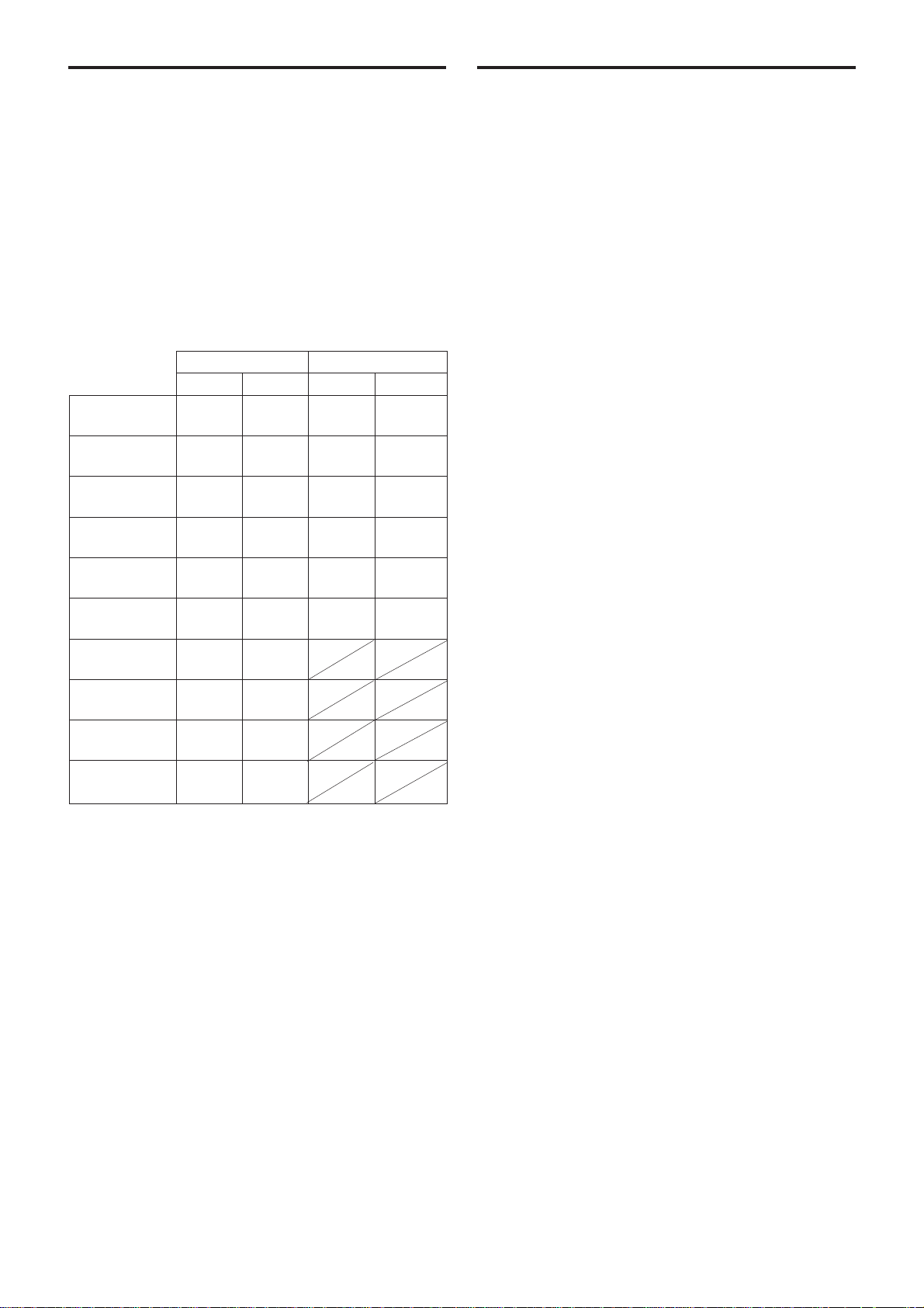
Pan/Tilt
Pan/Tilt is a function used to move a camera up and
down or left and right, however this camera supports a
video mode much smaller than the CCD’s effective
pixels by cutting out images from the whole screen.
You can specify the portion to be cut out using Pan/
Tilt commands. One unit of movement is two pixels.
Refer to the table for the video modes in which Pan/
Tilt commands can be used and the variable ranges for
the mode. The values in parentheses are the initial
settings.
XCD-SX910CR/SX910UV/SX910
Pan Tilt Pan Tilt
Format0Mode5 0 - 752 0 - 560 0 - 384 0 - 288
640 × 480 (376) (280) (192) (144)
Format0Mode6 0 - 752 0 - 560 0 - 384 0 - 288
640 × 480 (376) (280) (192) (144)
Format1Mode2 0 - 592 0 - 440 0 - 224 0 - 168
800 × 600 (296) (220) (112) (84)
Format1Mode5 0 - 368 0 - 272 Not Not
1024 × 768 (184) (136) available available
Format1Mode6 0 - 592 0 - 440 0 - 224 0 - 168
800 × 600 (296) (220) (112) (84)
Format1Mode7 0 - 368 0 - 272 Not Not
1024 × 768 (184) (136) available available
Format2Mode2 0 - 112 0 - 80
1280 × 960 (56) (40)
Format2Mode6 0 - 112 0 - 80
1280 × 960 (56) (40)
Format7Mode3 0 - 16 0 - 16
1376 × 1024 (8) (8)
Format7Mode4 0 - 368 0 - 16
1024 × 1024 (184) (8)
When a video mode is changed, the initial Pan/Tilt
values for the mode are set.
On the XCD-SX910CR/X710CR, if you set the value
of Pan/Tilt to maximum, the pixels on the edge of the
picture may not be output correctly.
XCD-X710CR/X710
Memory Channels
This camera is equipped with two channels nonvolatile memory to hold camera settings.
The settings of all camera features and the video mode
can be stored.
The camera memorizes the channel most recently used
to read out the setting information, and retains it, even
if the power is turned off. Therefore, the camera loads
the information from that channel when the power is
turned on.
The video mode settings are loaded only when the
power is turned on.
To start up the camera with the desired setting, perform
the following procedure.
1 Make changes to the camera features or the video
mode settings.
2 Store the current setting in Memory Channel 1 or
Memory Channel 2.
3 Load the information that was stored in step 2.
Thus, when you start up the camera the next time,
the settings that you have made will be loaded
automatically.
Using the CameraInitialize command, the setting
information stored in the channels is cleared and the
camera features and the video mode are initialized. To
preserve the information in the channels, be sure not to
send the CameraInitialize command while driver
software or application software is starting up.
The value of Pan/Tilt is initialized when the video
mode is changed. To preserve the value, be sure not to
change the video mode while driver software or
application software is starting up, or before sending
the video start command.
XCD-SX910CR/X710CR
XCD-SX910UV
XCD-SX910/X710
10
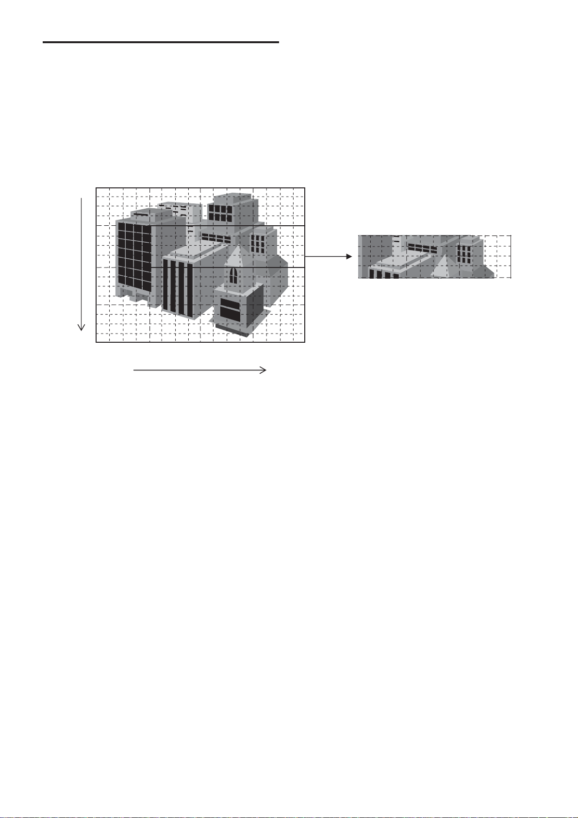
Partial Scan
The partial scan mode is a function for outputting part
of the full images a region of interest on the whole
image. Based on the unit cell as the unit, continuous
parts can be selected. Only rectangles can be selected.
The screen cannot be cut in convex and L
shapes.
Functions
Cutting by partial scan mode
Vertical (Vertical Direction)
Horizontal (Horizontal Direction)
The unit size of both the XCD-SX910CR/SX910UV/
SX910 and the XCD-X710CR/X710 is 1/256th of the
whole screen, divided into 16 sections, horizontally
and vertically.
The partial scan mode for the XCD-SX910CR/
SX910UV/SX910 and the XCD-X710CR/X710 has
had a partial read out function added, and there is a
frame rate speed-up feature for use when the vertical
width of the cut-out is small. But because of the
structure of the CCD, no matter how small the cut-out
width is horizontally, the frame rate cannot be
increased.
When Partial scan mode is used, set Format7, Mode 0.
XCD-SX910CR/X710CR
XCD-SX910UV
XCD-SX910/X710
11

Binning Mode
The mode used when the sensitivity is increased and
the frame rate is multiplied based on mixing the CCD
pixel data, is called the Binning mode.
There are two types of binning: 1 × 2 binning when the
output image is compressed in the vertical direction
only, and 2 × 2 binning when the image is compressed
in the horizontal direction also.
When binning mode is used, set either Format7 Mode
1 (2 × 2 binning), or Format7 Mode 2 (1 × 2 binning).
The specifications for each model are given below.
XCD-SX910UV/SX910 XCD-X710
Format7Mode1 640 × 480 512 × 384
(2 × 2 binning) Mono8 30/15 fps Mono8 50/25 fps
Mono16 15/7.5 fps Mono16 25/12.5 fps
Format7Mode2 1280 × 480 1024 × 384
(1 × 2 binning) Mono8 30/15 fps Mono8 50/25 fps
Mono16 15/7.5 fps Mono16 25/12.5 fps
Functions
Partial scan is not available in Binning Mode.
Be careful. If the exposure time is set slower than the
frame rate in the shutter setting, the frame rate may
also drop with respect to the exposure time.
Format7 Mode3/4 for XCD-SX910CR/ SX910UV/SX910
Only the XCD-SX910CR/SX910UV/SX910 supports
Format7, Mode3 and Mode4.
XCD-SX910CR/SX910UV/SX910
Format7Mode3 1376 × 1024
Mono8 15/7.5 fps
Mono16 7.5/3.75 fps
Format7Mode4 1024 × 1024
Mono8 15/7.5 fps
Mono16 7.5/3.75 fps
Partial scan is not available in these modes.
XCD-SX910CR/X710CR
XCD-SX910UV
XCD-SX910/X710
12
 Loading...