

Page 1

Digital Camera
Module
A-CUJ-100-11 (1)
Technical Manual
XCD-V60CR/SX90CR/U100CR
(Color model)
XCD-V60/SX90/U100
(Black and white model)
© 2007 Sony Corporation
Page 2

Table of Contents
Overview
Main Features ........................................................ 3
System Components .............................................. 4
Connection Diagram ............................................. 5
Location and Function of Parts and Operation .. 6
Front/Top/Bottom ............................................... 6
Rear .................................................................... 6
Installation ............................................................. 7
Fitting the lens .................................................... 7
Using a tripod ..................................................... 7
Connecting the camera cable ............................ 7
When power supply from the IEEE1394b
connector is insufficient ................................... 7
Functions
Gain ........................................................................ 8
Shutter .................................................................... 8
Absolute Value Control for the Shutter ............... 8
Auto Exposure ....................................................... 9
Gamma ................................................................... 9
Lookup Table ......................................................... 9
3 × 3 Image Filter .................................................. 9
Trigger .................................................................. 10
Pan/Tilt ................................................................. 11
Brightness ............................................................. 11
Sharpness (Black and white models only) ......... 11
Saturation (Color models only) .......................... 11
White Balance (Color models only) ................... 11
Hue (Color models only) ..................................... 11
Trigger Delay ....................................................... 11
GPIO ..................................................................... 11
Strobe Control ..................................................... 12
Setting AE/AWB Control Frame and Parameters
................................................................................ 12
Test Charts ........................................................... 12
Changing Bayer Patterns (Color models only) . 12
Trigger Inhibition ................................................ 12
User Free Memory ............................................... 12
Memory Shot ....................................................... 13
Broadcast Command ........................................... 13
1394 Bus Synchronization .................................. 13
Partial Scan .......................................................... 14
Binning Mode ....................................................... 15
Format7 Mode4 for XCD-V60/V60CR .............. 15
16-bit Mode .......................................................... 15
Control
Camera Command Status Register ....................16
ConfigurationROM ..............................................17
Control Base Address ..........................................19
Inquiring about Supported Video Modes ..........19
Video Mode Settings (S800) ................................20
Video Mode Settings (S400) ................................20
Starting/Stopping Video Transfer
(ContinuousShot) .................................................20
OneShot and MultiShot .......................................20
Control of IIDC Standard Features ...................21
The formula for absolute value shutter control
register address ...............................................24
Control of IIDC Optional Features ....................25
Control of Sony’s Unique Features ....................26
LUT (LookUp Table) ........................................26
3 × 3 Filter ........................................................27
Display of Test Chart ........................................27
Trigger Inhibition ..............................................28
User Free Memory ............................................28
Setting AWB (Auto White Balance) Parameters
.........................................................................29
Setting AE (Auto Exposure) Parameters ..........29
Memory Shot ....................................................30
Notes on the Camera Operations .......................31
If Frame Rate Decrease Occurs ........................31
When Using Trigger Mode ...............................31
On Sensitivity in Binning Mode .......................31
Auto Shutter Control and Absolute Value Shutter
Control ............................................................31
On Accuracy of Auto White Balance ...............31
Specifications
Specifications ........................................................32
Video Modes Supported ......................................33
Appendix
Spectral Sensitivity (Relative Response)
Parameters ............................................................35
Dimensions ............................................................37
2
Page 3

Overview
the cameras, or exposure starts on all the cameras
simultaneously using a software trigger.
The six models of the XCD-series digital camera
modules (Black and white models and RAW color
models) employing the IEEE1394b-2002 standard are
equipped with quality digital camera features.
Although it is compact, the camera allows high-speed
image transfer and daisy chain connection with two
IEEE1394b connectors. The camera also has versatile
features such as hardware preprocessing in the camera
that reduces the load of image processing in a PC, bus
synchronization, and broadcast delivery of commands.
The XCD-series digital output cameras conforming to
the IIDC 1.31 protocol take full advantages of
IEEE1394 capabilities.
Main Features
High image quality, high-speed image
output
The image device, output frame rate and resolution of
the cameras are as follows:
XCD-V60/V60CR: 1/3-type PS IT CCD, 90 fps, VGA
XCD-SX90/SX90CR: 1/3-type PS IT CCD, 30 fps,
SXGA
XCD-U100/U100CR: 1/1.8-type PS IT CCD, 15 fps,
UXGA
Memory channel
The memory channel allows storage of up to 15 sets of
camera settings such as gain and shutter.
Bulk trigger mode
The Bulk trigger mode allows output of multiple images
with a shot of a trigger signal. Each image is shot with
the camera settings stored in the memory channel. Up to
15 image settings are possible.
Memory Shot
The image exposed from the sensor is stored in the
camera’s built-in memory. The stored image can be read
out using a command from the host PC when required.
Standard image
size (H × V)
Bit
length
Mono8/
Raw8
Mono16/
Raw16
XCD-V60/
V60CR
640 × 480
(VGA)
54 frames 13 frames 8 frames
27 frames 6 frames 4 frames
XCD-SX90/
SX90CR
1,280 × 960
(SXGA)
XCD-U100/
U100CR
1,600 × 1,200
(UXGA)
Overview
Daisy chain connection
The camera is equipped with two IEEE1394b
connectors that support connection of multiple cameras.
As the power can be supplied from a 12-pin connector
(EIAJ), the camera achieves daisy chain connection
without limitation of power supply capacity so that a
simple image processing system with multiple cameras
can be developed.
Hardware preprocessing
The camera is equipped with hardware LUT (Lookup
Tab le).
The black and white models are also equipped with 3 ×
3 pixel matrix operation.
Bus synchronization
The cameras connected to the same bus automatically
operate in synchronization with the 1394 bus, without
using an external sync signal. The exposure timing on
multiple cameras is synchronized correctly via the
IEEE1394b cable only.
Partial scan
Partial scan clips a required angle of view (area) from
the entire screen to be read out. As a part of the image is
read out, the unit takes advantage of reduced image data
and high-speed transfer. The minimum clipping unit is
32 pixels × 24 lines.
Binning
Binning increases the sensitivity and frame rate based on
mixing the pixel data.
9-pin connector with fixing screws
Low power consumption, vibrationresistant structure, and compact size
IIDC Ver.1.31 protocol compliant
Broadcast delivery of commands
The camera settings for all the cameras connected to the
same bus can be changed at the same time. For example,
the gain or shutter speed is set to the same value on all
3
Page 4

System Components
The camera module imaging system comprises the following products.
Overview
Products 1 to 4 are used for the basic configuration, and 1 to 7 for the optional configuration. (All the products
except the camera module are available separately.)
1
4
1 Camera module
This is a small-size, high-resolution, camera
module using a CCD image sensor.
2 IEEE1394b camera cable (commercially
available)
Connect this cable to the IEEE1394b connector on
the rear panel of the camera module. The power and
image/control signals are transmitted through this
cable. To prevent a poor connection or damage to
the camera or cable, use the cable equipped with
fixing screws.
5
2
3
6
6 DC-700/700CE camera adaptor (Sony)
Connect this adaptor to the camera module to
enable power supply from an ordinary AC power
source.
7 CCXC-12P02N (2 m, 6.6 ft)/05N (5 m, 16.4 ft)/
10N (10 m, 32.8 ft)/25N (25 m, 82 ft) camera
cable (Sony)
Connect this cable to the 12-pin I/O connector on
the rear panel of the camera module. The cable is
used for power supply and exchange of trigger
signals.
7
3 C-mount lens (commercially available)
Use an appropriate lens for the camera module and
usage.
4 Camera module interface board (commercially
available)
Install the board in a PCI bus slot of a host device
such as a PC.
Select an IEEE1394 interface board to match your
system.
Select an IEEE1394b interface board if you use the
transfer speed of 800 Mbps.
5 VCT-ST70I tripod adaptor (Sony)
Attach this adaptor to the bottom of the camera
module to fix the camera module to a tripod.
4
Page 5
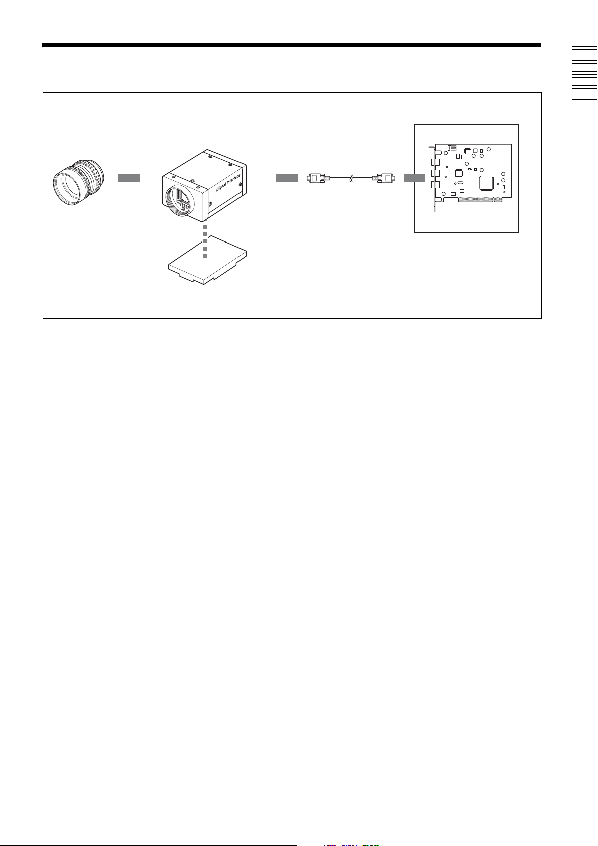
Connection Diagram
XCD-V60/V60CR/SX90/
SX90CR/U100/U100CR
C-mount lens
Overview
IEEE1394b cable
Host adaptor card
Host equipment (PC, etc.)
VCT-ST70I Tripod
Adaptor
5
Page 6
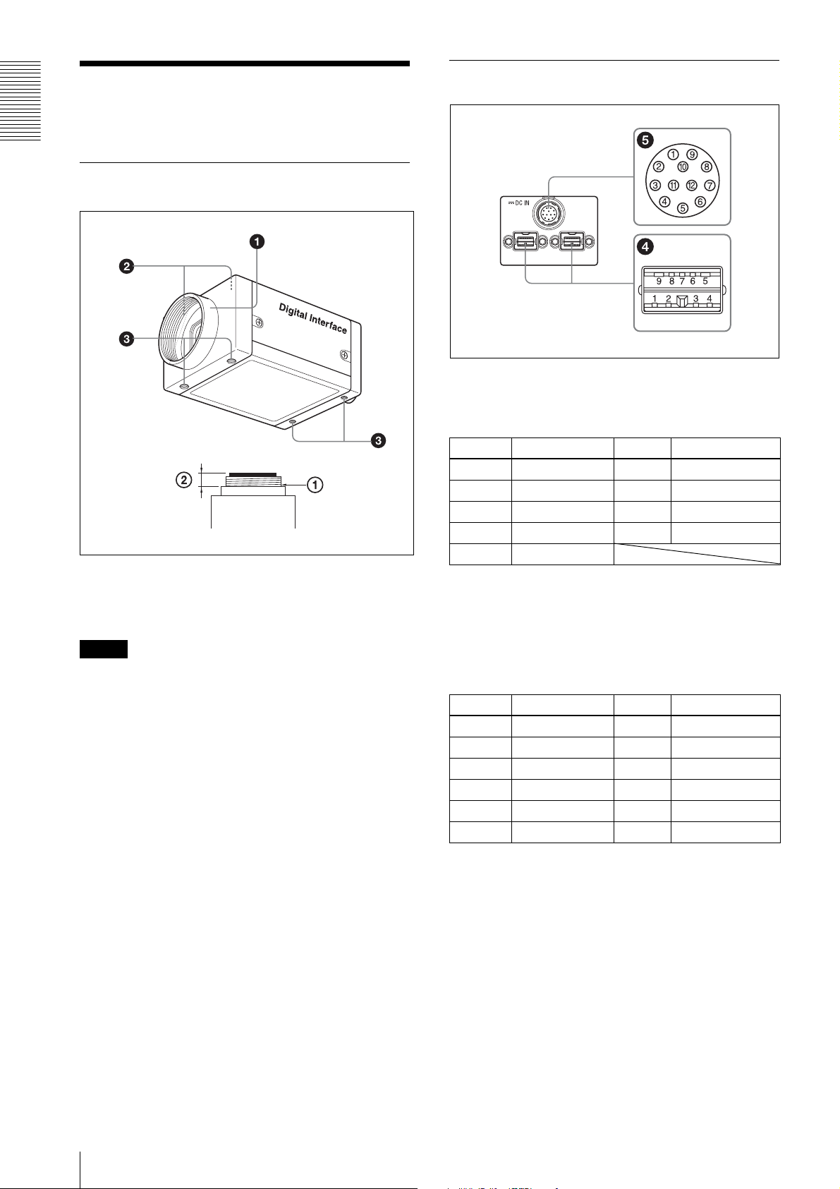
Rear
Location and Function of Parts and Operation
Overview
Front/Top/Bottom
4 IEEE1394b connectors
Connect an IEEE1394b camera cable (not
supplied) to this connector.
Pin No. Signal Pin No. Signal
1TPB– 6VG
2TPB+ 7NC
3TPA– 8VP
4TPA+ 9TPBG
5TPAG
1 Lens mount (C-mount)
Attach any C-mount lens or other optical
equipment.
Note
The lens must not project more than 10 mm (13/32 inch)
from the lens mount.
1 Lens mount face 210 mm (13/32 inch) or less
2 Auxiliary holes (top)
3 Reference holes (bottom)
These precision screw holes are for locking the
camera module. Locking the camera module into
these holes secures the optical axis alignment.
For details, see “Dimensions” on page 37.
Four screw reference holes 3 can be used as the
tripod adaptor screw holes, too. Screw the VCTST70I tripod adaptor into the four screw holes
when you use a tripod.
5 12-pin I/O connector
When power from the IEEE1394b connector is
insufficient, power is supplied through this
connector.
Connect a camera cable such as the CCXC-12P05N
to this connector.
Pin No. Signal Pin No. Signal
1 Power GND 7 GPIO IN 2
2 Power IN 8 GPIO OUT 2–
3 ISO GND 9 GPIO OUT 2+
4 Strobe OUT 10 GPIO IN 1
5 GPIO OUT 1– 11 Trigger IN
6 GPIO OUT 1+ 12 ISO GND
6
Page 7
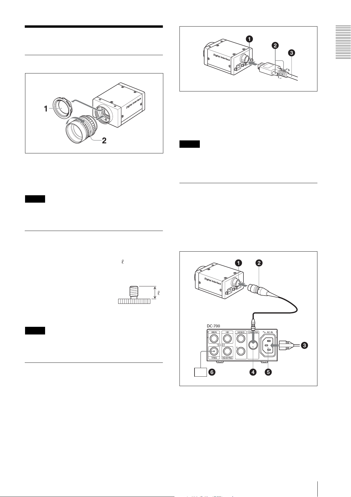
Installation
Fitting the lens
1
Remove the lens mount cap.
2
Screw in the lens (not supplied), and turn it until it
is secured.
Note
Clean the optical filter with a commercially available
blower brush to remove dust.
Using a tripod
To use the tripod, install the VCT-ST70I tripod adaptor
(not supplied) on the camera module.
Use a tripod screw with a protrusion ( ) extending
from the installation surface, as follows:
Overview
1 IEEE1394b connector
2 Fixing screws
3 IEEE1394b camera cable (not supplied)
Note
Loose fixing screws may cause a poor connection or
damage to the camera or cable. Be sure to tighten the
fixing screws.
When power supply from the IEEE1394b connector is insufficient
Power can be supplied to the camera module via the DC700/700CE camera adaptor (optional) and a camera
cable such as CCXC-12P05N (optional) if power supply
from the IEEE1394b connector is insufficient.
ISO standard: Length 4.5 mm to 5.0 mm
ASA standard: Length 0.197 inches
Tighten the tripod screws using a hand screwdriver.
Note
When you install the tripod adaptor, use the screws
supplied with the tripod adaptor.
Connecting the camera cable
Connect a commercially available IEEE1394b camera
cable to the IEEE1394b connector and the 1394b
interface connector of your PC. When you connect the
cable, insert the cable connector into the IEEE1394b
connector until it snaps into place, holding it. Then,
tighten the fixing screws placed on both sides of the
cable connector.
1 12-pin I/O connector
2 Camera cable (e.g. CCXC-12P05N)
3 to AC power source
4 CAMERA connector
5
~ AC IN connector
6 Trigger generator
7
Page 8

Functions
16 s
Gain
Both Manual and Auto Gain settings are available with
this camera.
Functions
The variable range extends from 0 to 24 dB for the black
and white models or from 0 to 18 dB for the color
models. The camera is designed so that the gain can be
subdivided and set by 0.0359 dB.
At the factory default setting, the gain is set to 0 dB.
When Auto Gain is selected, the gain is adjusted
automatically, based on the brightness of the subject. At
this time, the reference level (target point) is set in the
AutoExposure register.
For details on AutoExposure, see “Auto Exposure” on
page 9.
1 s
1
10 µs
3 1000
When Auto Shutter is selected, the exposure time is
adjusted automatically, based on the brightness of the
subject. At this time, the reference level (target point) is
set in the AutoExposure register.
For details on AutoExposure, see “Auto Exposure” on
page 9.
2
1150
Shutter
This camera allows both Manual and Auto Shutter
settings.
The variable range extends from 10 microseconds to
16.0 seconds; relative values are indicated by a 12-bit
integer, and absolute values are indicated using a 32-bit
floating point value.
The relationship between the parameter and the
exposure time is given by the following formulas,
where:
P = Parameter (003h to 47Eh)
E = Exposure time (s)
If P= 3
E = 0.00001
If 4 <= P <= 1000
1
If 1000 <= P <= 1150
For long exposure times
When the exposure time is longer than the frame period,
the camera enters the long exposure time mode, and the
actual frame rate is reduced in accordance with the
exposure time.
Absolute Value Control for the Shutter
This camera allows control of exposure time using
absolute values. The values are indicated using a 32-bit
floating point value. (Unit: sec.)
The variable range of absolute values extends from 10
microseconds to 16.0 seconds.
Programming example
union
{
DWORD dwValue; // 1394 is expressed in quadlets,
float fValue; // exposure time is indicated in seconds.
} AbsoluteShutterValue;
Setting examples
3 (003h) : 10 µs (1/100000)
32 (020h) : 1 ms (1/1000)
100 (064h) : 10 ms (1/100)
1000 (3E8h) : 1 s
1010 (3F2h) : 2 s
1150 (47Eh) : 16 s
8
AbsoluteShutterValue.fValue = Exposure time;
WriteQuad(AbsoluteShutterOffsetAddress,
AbsoluteShutterValue.dwValue);
WriteQuad is a virtual function used to write in the 1394
register.
AbsoluteShutterOffsetAddress is an offset address for
the absolute value control.
See “ConfigurationROM” on page 17 for the formula
for the offset address.
Page 9

Auto Exposure
Lookup Table
AutoExposure is a function that automatically adjusts
the gain and shutter settings, based on the brightness of
the subject. When the gain or shutter is set to Auto, the
brightness is adjusted automatically to the value
specified with AutoExposure.
Gamma
This camera uses the gamma function to select the
lookup table.
0: Linear
1: Reverse
2: Equivalent of Gamma = 0.70
3: User setting
To set an arbitrary gamma curve, prestore the setting
values in the lookup table (EEPROM) of the camera.
The lookup table of this camera consists of 1,024 tables
with10-bit input and 10-bit output.
The lookup table allows setting of an arbitrary gamma
curve or binary segmentation.
Functions
3 × 3 Image Filter
For black and white models only, simple image
processing using the 3 x 3 image filter is possible on
hardware.
0: Filter OFF
1: Sharpness enabled
2: Horizontal edge detection (Type 1)
3: Vertical edge detection (Type 1)
4: Horizontal edge detection (Type 2)
5: Vertical edge detection (Type 2)
6: Edge emphasis (Type 1)
7: Edge emphasis (Type 2)
8: User setting
Note
Sharpness is disabled when the 3 × 3 image filter is set
to 0, or 2 to 8.
9
Page 10
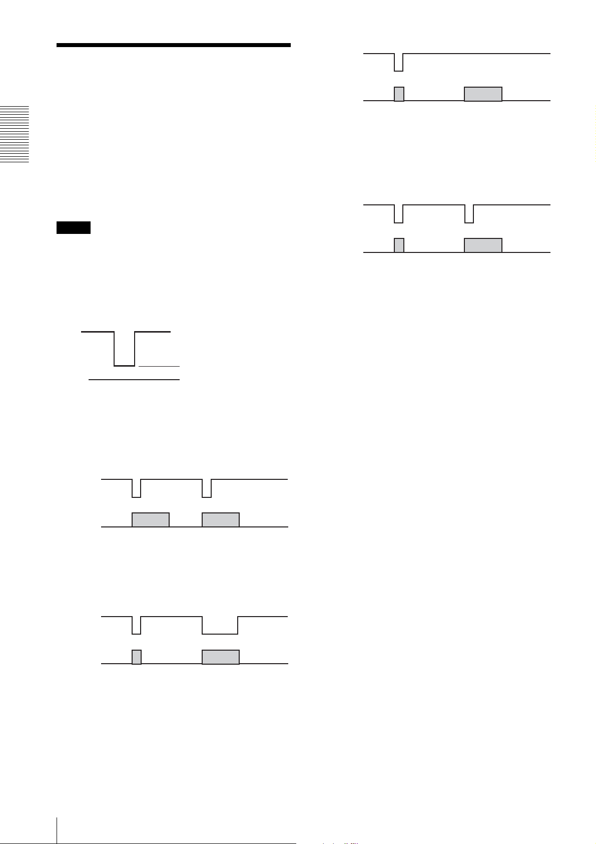
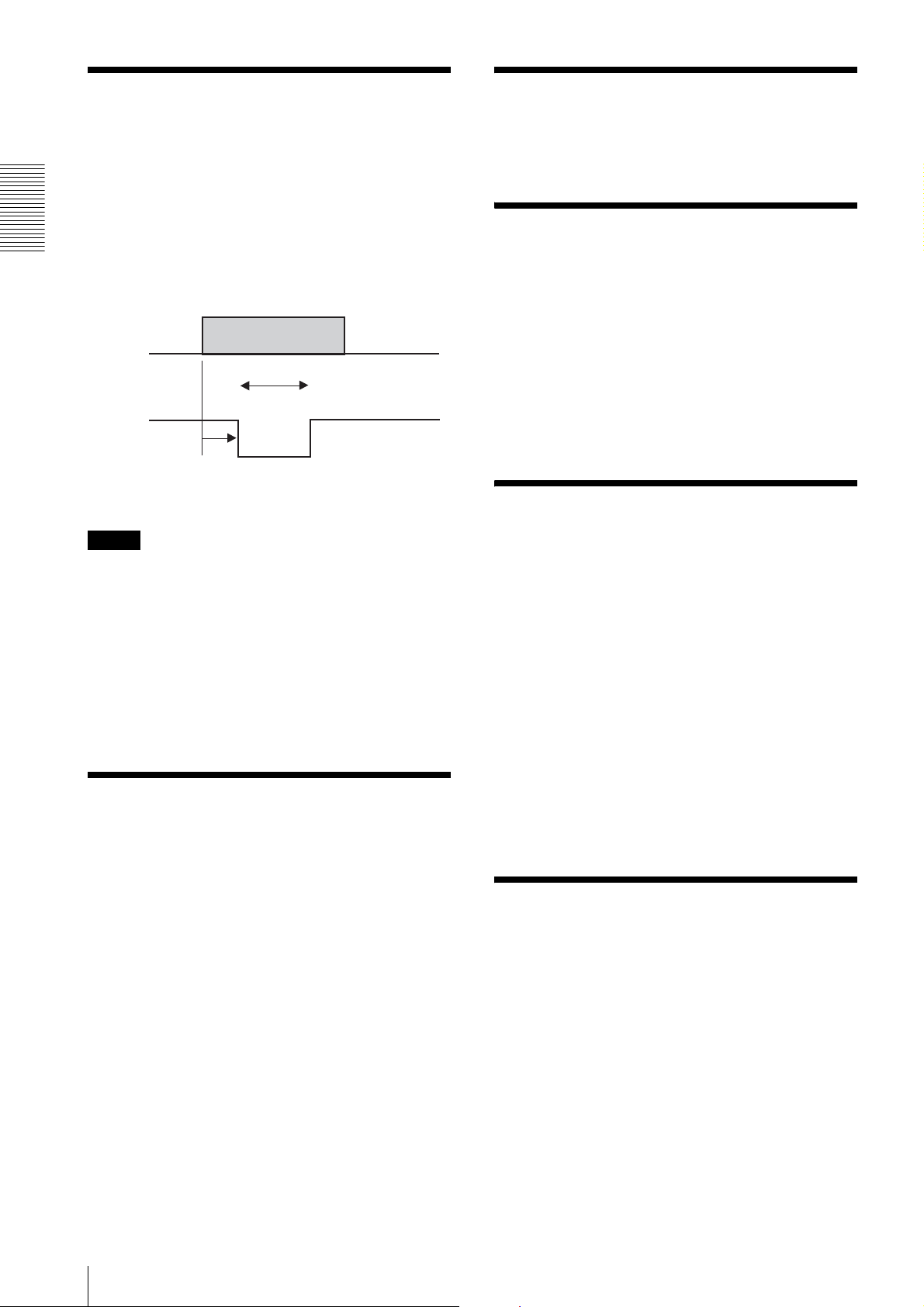
Trigger
Trigger
Trigger shutter is useful for capturing images in
response to a trigger that starts the exposure to match a
preset timing. It can also be used to capture an image
using multiple cameras with the same timing.
When a trigger shutter is used, the required trigger is
input via the 12-pin connector on the rear panel. The
Functions
input signal is a 5 to 24 V negative pulse.
As the input connector is pulled inside of the camera, the
camera can receive a trigger only by short-circuiting the
input pin and ISO (GND) pin.
Note
To connect to ground, use a device having a minimum
pulse width of 10 microseconds and an input current of
0.5 mA or more.
Exposure
Setting in Memory
channel 1
Setting in Memory
channel 2
Trigger mode 15 (Sequential trigger mode)
Trigger mode 15 allows shooting of images by loading
the camera settings prestored in memory channels in
sequence each time a trigger is input.
Trigger
Exposure
Setting in Memory
channel 1
Setting in Memory
channel 2
This camera supports four trigger modes: 0, 1, 14 and
15.
As this camera is equipped with 15 memory channels, a
repeat pattern of up to 15 image shootings can be set for
High level: 5 to 24 V DC
trigger mode 14 or 15.
The number of the repeat patterns to be set in one cycle
can be determined by the parameter of the trigger mode.
Low level: 0 to 0.44 V DC
0 V DC
Memory channel 0 is not used for the Bulk trigger mode
and the Sequential trigger mode.
Trigger mode 0
Trigger mode 0 starts exposure by detecting the falling
edge of a trigger signal. The exposure time is determined
by the shutter parameter.
Trigger
Exposure
Trigger mode 1
Trigger mode 1 controls the exposure time using the
width of the trigger signal pulse. When trigger mode 1 is
used, there is actually no limit to the exposure time.
Trigger
Exposure
The following features are loaded from the memory to
be set for shooting:
– Brightness
– Sharpness
– Saturation
– White balance
– Hue
– Gamma
– Shutter
– Gain
– Pan/Tilt
– Optical Filter
Note that the Auto mode of White Balance, Shutter and
Gain cannot be set.
Also note that Pan/Tilt is set only when the current video
mode is the same as the video mode selected when the
setting has been stored in the memory channel.
This camera can also be used with a software trigger that
issues the trigger signal via software command. Trigger
modes 0, 1, 14 and 15 can be used with software
triggers.
Trigger mode 14 (Bulk trigger mode)
Trigger mode 14 allows shooting of multiple images
with different camera settings using only one trigger
signal. The camera settings should be prestored in
memory channels.
10
Page 11

Pan/Tilt
Hue (Color models only)
Pan/Tilt is a function used to move a camera up and
down or left and right. However this camera supports a
video mode much smaller than the CCD’s effective
pixels by cutting out images from the whole screen. You
can specify the portion to be cut out using Pan/Tilt
commands.
The variable range differs according to the selected
video mode.
When a video mode is changed, the pan/tilt values are
set to the default setting.
Brightness
This feature controls the black level of a video image.
Sharpness (Black and white models only)
This feature controls the image quality.
A smaller value makes the image softer, and a larger
value makes it sharper.
The Sharpness feature cannot be used together with the
3 × 3 filter.
When the white balance cannot be obtained with the R
and B level adjustment, you can change the G level by
hue adjustment. Normally use the default hue setting.
Trigger Delay
Issue of a trigger signal can be delayed from the external
trigger inside the camera.
This delay adjustment is useful to get an appropriate
shooting timing when the position of the subject is not
good at a regular trigger timing.
GPIO
A general-purpose I/O port with a 2-bit output and 2-bit
input is assigned in the 12-pin connector.
This port is used for reading information of external
switches and sensors from the camera and controlling
external devices.
The output terminal is of the open-collector type and
should be pulled outside of the camera (5 to 24 V).
Note on input
Connect to ISO (GND) using an input device with a
minimum signal width of 0.5 msec and an input current
of 0.5 mA or more.
Functions
Saturation (Color models only)
This feature controls the color density.
White Balance (Color models only)
This feature controls the white balance by setting the R
and B levels relative to the G level.
The camera also supports the Auto white balance by
which the camera automatically adjusts the white
balance.
Note on output
Use the following conditions:
Recommended pull-up resistor: 4.7 kΩ
Recommended pull-up voltage: 5 V
Minimum signal width: 0.5 msec
The camera is equipped with a protective resistor of 220
Ω. If the above conditions prove difficult in use, check
the output voltage and determine the external pull-up
resistor.
11
Page 12
Strobe Control
Test Charts
A strobe control signal is assigned in the 12-pin
connector. This allows direct command of lightemission from the strobe connected to the camera and
controls the light-emission timing and the signal width.
The output terminal is of the open-collector type and
should be pulled at the strobe side. A strobe that emits
Functions
light by short-circuiting the input to ground can be
connected to the camera directly.
A color bar chart (for color models only) and a gray
scale chart can be output.
Changing Bayer Patterns (Color models only)
Llight-emission
timing
Width
Strobe output
signal
Delay
The color models of this camera series output raw data.
For these models, the correct color reproduction is not
obtained if the Bayer pattern in the application software
does not match that in the camera. The output pattern
can be set at the camera if the application is not equipped
with the pattern setting.
Trigger Inhibition
Note
Use the following conditions:
Recommended pull-up resistor: 4.7 kΩ
Recommended pull-up voltage: 5 V
The camera is equipped with a protective resistor of 220
Ω. If the above conditions prove difficult in use, check
the output voltage and determine the external pull-up
resistor. The camera is capable of outputting a signal of
about 10 microsecond width, although the rise time
depends on the pull-up resistor.
Setting AE/AWB Control Frame and Parameters
At the factory default setting, this camera accepts trigger
input quickly and no triggers are inhibited.
If the camera is used under noisy conditions with this
setting, noise may enter before a trigger input is
accepted, causing image disturbance.
If the trigger inhibition is enabled in such a condition,
the camera does not accept a new trigger until the image
output is completed and achieves stable operation.
With the trigger inhibition enabled, however, exposure
cannot be performed during image output.
Consequently, an acceptable trigger cycle becomes
longer according to the exposure time.
For example, when exposure is set to 1/30 s in 30 fps
mode, the trigger cycle becomes almost double, that is,
equivalent to 15 fps.
The detection frame for Auto Exposure and Auto White
Balance can be set.
Determine the detection frame in percentage units
taking the width and height of the output image as 100
%.
The control speeds for Auto Exposure and Auto White
Balance can also be set. Raise or lower the response
speed for each application respectively.
For Auto Exposure, the restart conditions can also be
set, that is the conditions once Auto Exposure
adjustment has concluded and after the gain and shutter
changes have been restored to a stable state, and a new
change in video image becomes visible.
In the Auto Exposure or Auto White Balance parameter
setting mode, the set frame is highlighted on the video
image.
12
User Free Memory
This camera is equipped with a 256-byte memory space
so the user can write and read data freely.
The written data is retained after the power is turned off.
For example, the user can name the camera and note the
installation conditions using this memory space.
The memory content is retained even if the camera
initialization is performed.
Page 13

Memory Shot
1394 Bus
The camera is equipped with Memory Shot that
temporarily stores an image in the frame memory inside
the camera and transfers it later.
When multiple cameras are connected in the same bus,
all the cameras may not output images at the same time
due to the restriction of 800 Mbps band. Memory Shot
may resolve this inconvenience.
When exposure starts, each camera stores an image in
the frame memory without allocating the isochronous
resource.
When outputting, each PC outputs the image from the
camera allocating the isochronous resource.
The number of images to be stored depends on the video
mode.
Broadcast Command
The normal1394 communication method specifies the
node number at the host side so that only a specified
camera responds to the command.
If the node number is set to 63, all the cameras
connected to the same bus can receive the command
simultaneously, i.e., only one command issued from the
host can control multiple cameras at the same time.
Synchronization
Timing used to start exposure is synchronized with the
1394 bus time cycle register.
If cameras are connected to the same bus, they are
automatically synchronized in a 1394 bus operation. As
800 Mbps band restriction can affect the
synchronization, you must set the video mode in which
the cameras can transmit a video signal at the same time.
1394 synchronization does not work in long exposure
mode and Partial scan mode. In a long exposure, the
exposure time is set longer than the image transmission
cycle.
1394 bus synchronization includes up to 1H cycle jitter.
Hardware external synchronization will ensure greater
accuracy.
Functions
Example: To broadcast a software trigger
1. Connect multiple cameras to the same bus.
2. Set the video mode and frame rate appropriately on
each camera and prepare the cameras for sending
images at the same time.
3. Set each camera to the software trigger mode.
4. Issue a software command for node number 63.
Now all the cameras start exposure and output images
simultaneously.
All the commands including the video mode setting and
the feature control are capable of broadcasting except
the block writing command.
When setting different types of cameras using a
broadcast command, be careful not to issue a command
that the cameras do not support.
13
Page 14

Partial Scan
The partial scan is a function for outputting part of a whole image as a region of interest on the whole image. Based on
the unit cell as the unit, continuous parts can be selected. Only rectangles can be selected. The screen cannot be cut in
convex and L shapes.
Vertical (Vertical Direction)
Functions
Horizontal (Horizontal Direction)
Cutting by Partial scan mode
The minimum unit size for partial scan is 32 pixels × 24 lines. The cut-out position can be set in unit of 4 pixels × 4 lines.
For high-speed scanning, set the maximum packet size.
When using multiple cameras at the same time, set a small packet size that falls within the 800 Mbps band.
When using Partial scan mode, set Format7, Mode0.
14
Page 15

Binning Mode
The mode used when the sensitivity is increased and the
frame rate is multiplied based on mixing the CCD pixel
data, is called the Binning mode.
There are two types of binning: 1 × 2 binning when the
output image is compressed in the vertical direction
only, and 2 × 2 binning when the image is compressed in
both the vertical and horizontal directions.
When Binning mode is used, set either Format7 Mode1
(2 × 2 binning), or Format7 Mode2 (1 × 2 binning).
Format7 Mode4 for XCDV60/V60CR
As 90 fps mode is not defined by the IIDC standard, this
camera realizes 90 fps mode in Format7, Mode4.
16-bit Mode
Functions
This camera supports 16-bit Black & white
(Monochrome) mode. Only the least significant 10 bits
of the 16 bits will handle data. The upper 6 bits will be
filled with zeros.
000000dd dddddddd
15
Page 16

Control
Camera Command Status Register
This camera complies with IIDC 1394-based Digital Camera Specification, Version 1.31 (hereinafter referred to as IIDC
v1.31).
The standards document can be purchased from 1394TA (the 1394 Trade Association). As it is very helpful in
understanding the explanations in this Technical Manual, we recommend that you purchase a copy of IIDC v1.31.
Memory Map
Control
BusID
bbbbbbbb bbnnnnnn 11111111 11111111 11110000 11110000 00000000 00000000
NodeID
Must be 1 Address used by the camera
1394 devices have a 64-bit address space. The upper 10
bits show the bus ID (0-1023), and the next six bits show
the node ID (0-63). The IIDC standards require the next
20 bits to be 1.
The remaining 28 bits can be allocated to the camera as
addresses.
The bus and node IDs may be changed if the topology is
restructured because of bus reset, so only the least
significant 32 address bits are shown in this Guide.
Address Resister
F0000000 Base address
F0000400 ConfigROM area
F0F00000 Base address for camera
commands
F0F00000 CameraInitialize
F0F00100 Video Format Inq
F0F00180 Video Mode Inq
F0F00200 Frame Rate Inq
F0F002E0 Format7 CSR Inq
F0F00400 Basic Func Inq
F0F00500 Feature Element Inq
F0F00600 Isochronous Control register
F0F0071C AbsoluteControlCSR Inq for
Shutter
F0F00800 FeatureControl
F0F00970 AbsoluteControlCSR for Shutter
F0F10000 Format7Mode0 CSR
F0F11000 Format7Mode1 CSR
F0F12000 Format7Mode2 CSR
F0F13000 Format7Mode3 CSR
F0F30000 AccessControlRegister
F0F40000 MemoryShotControl
F0F50000 UserFreeMemory
F0F60000 – F0F61FFC LookUpTable
F0F62000 – F0F62020 Filter
F0F63000 – F0F63024 AWB parameters
F0F64000 – F0F64020 AE parameters
16
Page 17

ConfigurationROM
The ConfigurationROM is normally used for the OS to identify the device.
The serial number and firmware version of the camera are stored in ConfigurationROM to be used when required. Note
that the setting method for the serial number and firmware version information is of Sony’s unique specification and is
not compatible with cameras of other manufacturers.
The following explanation uses XCD-V60CR as an example.
Offset 0-7 8-15 16-23 24-31
Bus Info Block 400h 04 22 ROM CRC
404h 31 33 39 34
408h 20 FF A2 13
40ch 08 00 46 10 NodeVendorID/ChipID-Hi
410h 00 37 1A 96 Chip ID-Lo
Root
Directory
With the exception of bits 8 to 15 of the 400h offset address field, the length of the entire ConfigROM is made up of
22h Quadlets. Therefore, the ConfigROM from 400h to 48Bh is 140 bytes.
414h 0003 CRC
418h 03 08 00 46 ModuleVendorID
41ch 0C 00 83 C0
420h D1 00 00 01 UnitDirectoryOffset
Control
The UnitDirectory offset address is required to be
424h + 000004h × 1 = 424h
Offset 0-7 8-15 16-23 24-31
Unit Directory 424h 0003 CRC
428h 12 00 A0 2D UnitSpecID
42Ch 13 00 01 02 UnitSoftwareVersion
430h D4 00 00 01 UnitDependentDirectory Offset
For offset address 424h, the length of the UnitDirectory is 3 Quadlets.
UnitSpecID (00A02Dh) conforms to 1394TA standards.
UnitSoftwareVersion (000102h) conforms to IIDC Standards, Version 1.3.
The offset address of UnitDependentInfo is required to be
430h + 000001h × 1 = 434h
Offset 0-7 8-15 16-23 24-31
Unit
Dependent
Info
434h 000B CRC
438h 40 3C 00 00 CommandRegsBase
43ch 81 00 00 0A VendorNameLeaf
440h 82 00 00 0D ModelNameLeaf
444h 38 00 00 10 Unit_sub_sw_version
448h 39 00 00 00 Reserved
44Ch 3A 00 00 00 Reserved
450h 3B 00 00 00 Reserved
454h 3C 00 01 00 Vendor_unique_info_0
458h 3D 01 00 00 Vendor_unique_info_1
45Ch 3E 00 00 30 Vendor_unique_info_2
460h 3F 01 86 A1 Vendor_unique_info_3
17
Page 18

Control
For offset address 434h, the length of the UnitDependentInfo is 0Bh Quadlets.
CommandRegsBase is the base address of the camera control register.
F0000000h + 3c0000h × 4 = F0F00000h
The offset address of VendorNameLeaf is required to be
43Ch + 00000Ah × 4 = 464h
The offset address of ModelNameLeaf is required to be
440h + 00000Dh × 4 = 474h
Unit_sub_sw_version conforms to IIDC Standards, Version 1.31.
Vendor_unique_info 0 to Vendor_unique_info 3 are terms of information that the vendor of the camera can define.
The meanings in this camera are as follows:
Vendor_unique_info_0 is the firmware version.
Vendor_unique_info_1 is the hardware version.
Vendor_unique_info_2 is the link version.
Vendor_unique_info_3 is the serial number of the camera.
VendorNameLeaf
Offset 0-7 8-15 16-23 24-31
Vender Name Leaf 464h 0003 CRC
468h 00 00 00 00
46h00000000
470ch 53 4F 4E 59
“ SONY ”
For offset address 464h, the length of the VendorNameLeaf is 3 Quadlets.
The subsequent 8 bytes are fixed at 00.
After that, the four characters for “SONY” are entered.
ModelNameLeaf
Offset 0-7 8-15 16-23 24-31
Model Name Leaf 474h 0005 CRC
478h 00 00 00 00
47ch 00 00 00 00
480h 58 43 44 2D
484h 56 36 30 43 “ V60C ”
488h 52 00 00 00 “ R··· ”
For offset address 474h, the length of the ModelNameLeaf is 5 Quadlets.
The subsequent 8 bytes are fixed at 00.
After that, the model name is entered.
“ XCD- ”
18
Page 19

Format7
Control Base Address
Every register address is decided based on the base
address found in the CommandRegsBase field of
ConfigrationROM. F0F00000h is the control base
address on this camera.
Inquiring about Supported Video Modes
First, we will find out what video formats are supported.
Data
Address XCD-V60/
V60CR
F0F00100h 81000000h E1000000h E1000000h
Next, for each format, we will find out which video
modes are supported.
Format0
Address XCD-V60/
V60CR
F0F00180h 06000000h 06000000h 06000000h
Format1
XCD-SX90/
SX90CR
Data
XCD-SX90/
SX90CR
XCD-U100/
U100CR
XCD-U100/
U100CR
Data
Address XCD-V60/
V60CR
F0F00180h F8000000h F0000000h F000000h
XCD-SX90/
SX90CR
XCD-U100/
U100CR
Next, for each video mode, we will find out which frame
rates are supported.
Data
Address XCD-V60/
F0F00214h
(Format0Mode5)
F0F00218h
(Format0Mode6)
F0F00228h
(Format1Mode2)
F0F00234h
(Format1Mode5)
F0F00238h
(Format1Mode6)
F0F0023Ch
(Format1Mode7)
F0F00248h
(Format2Mode2)
F0F00254h
(Format2Mode5)
F0F00258h
(Format2Mode6)
F0F0025Ch
(Format2Mode7)
FC000000h F8000000h F0000000h
FC000000h F8000000h F0000000h
XCD-SX90/
V60CR
– 38000000h 30000000h
– F8000000h F0000000h
– 78000000h 70000000h
– F8000000h F0000000h
– F8000000h F0000000h
– – F0000000h
– F0000000h F0000000h
– – F0000000h
SX90CR
XCD-U100/
U100CR
Control
Data
Address XCD-V60/
V60CR
F0F00180h 0000000h 27000000h 27000000h
XCD-SX90/
SX90CR
XCD-U100/
U100CR
Format2
Data
Address XCD-V60/
V60CR
F0F00180h 0000000h 22000000h 27000000h
XCD-SX90/
SX90CR
XCD-U100/
U100CR
19
Page 20

Video Mode Settings
Starting/Stopping Video
Control
(S800)
Select the video mode you want to use from the tables,
and make the required settings.
As examples, the register settings for Format0, Mode5,
and a frame rate of 60 fps for the XCD-V60; Format2,
Mode2, and a frame rate of 30 fps for the XCD-SX90,
and Format2, Mode5, and a frame rate of 15 fps for the
XCD-U100 are shown.
In addition, an isochronous transfer speed of 800 Mbps,
and isochronous channel 0 are used in these examples.
Normally, set the isochronous transfer speed to 800
Mbps.
When multiple cameras are used simultaneously, set
different isochronous channels for each.
Data
Address XCD-V60/
F0F00600h
(FrameRate)
F0F00604h
(VideoMode)
F0F00608h
(VideoFormat)
F0F0060Ch
(IsoChannel /
IsoSpeed)
V60CR
A0000000h 80000000h 60000000h
A0000000h 40000000h A0000000h
00000000h 40000000h 40000000h
00008003h 00008003h 00008003h
XCD-SX90/
SX90CR
XCD-U100/
U100CR
Transfer
(ContinuousShot)
In the device driver, after the preparations for receiving
isochronous data are made, video transfer starts when
the following commands are issued.
Address Data
F0F00614h 80000000h
When the following command is issued video transfer
stops.
Address Data
F0F00614h 00000000h
OneShot and MultiShot
This camera supports both OneShot and MultiShot
commands. With a OneShot command, after outputting
just one single-frame image, the camera enters an
“idling” state. With a MultiShot command, the camera
enters the “idling” state after outputting exactly the
specified number of images.
Video Mode Settings (S400)
When the camera is used under1394A (S400)
conditions, set the isochronous transfer speed to 400
Mbps.
In this case, set the frame rate to 15 fps, as this mode
does not support data transfer of SXGA 30 fps.
Data
Address XCD-V60/
F0F00600h
(FrameRate)
F0F00604h
(VideoMode)
F0F00608h
(VideoFormat)
F0F0060Ch
(IsoChannel /
IsoSpeed)
V60CR
A0000000h 60000000h 60000000h
A0000000h 40000000h A0000000h
00000000h 40000000h 40000000h
02000000h 02000000h 02000000h
XCD-SX90/
SX90CR
XCD-U100/
U100CR
OneShot
Address Data
F0F0061Ch 80000000h
MultiShot
Address Data
F0F0061Ch 4000nnnnh
nnnn indicates the number of frames to be output. You
can specify any number between 0001h and FFFFh (1
and 65535). If 0000h is specified, you can think of it as
being 1.
Execution of ContinuousShot, OneShot, and MultiShot
are prioritized as follows. When a command with higher
priority is being executed, the one with the lower priority
is ignored.
ContinuousShot > OneShot > MultiShot
20
Page 21

Control of IIDC Standard Features
Before transmitting the control command, check the variable ranges of settings and if there is an automatic mode for
each feature.
As the variable ranges of the settings vary with video modes for the Pan and Tilt features, be sure to check them if the
video mode is changed.
Address Data Bit
F0F00500h
(Brightness)
F0F00504h
(AutoExposure)
F0F00508h
(Sharpness)
(Black and white models
only)
F0F0050Ch
(WhiteBalance)
(Color models only)
F0F00510h
(Hue)
(Color models only)
F0F00514h
(Saturation)
F0F00518h
(Gamma)
890003FFh 0 This feature exists.
4 The value can be read out.
7 Manual setting can be selected.
8-19 Min. 0
20-31 Max. 1023
891003FFh 0 This feature exists.
4 The value can be read out.
7 Manual setting can be selected.
8-19 Min. 256
20-31 Max. 1023
89000007h 0 This feature exists.
4 The value can be read out.
7 Manual setting can be selected.
8-19 Min. 0
20-31 Max. 7
9B7009FFh 0 This feature exists.
4 The value can be read out.
6 Auto setting can be selected.
7 Manual setting can be selected.
8-19 Min. 1792
20-31 Max. 2559
897009FF 0 This feature exists.
4 The value can be read out.
7 Manual setting can be selected.
8-19 Min. 1792
20-31 Max. 2559
890401FF 0 This feature exists.
4 The value can be read out.
7 Manual setting can be selected.
8-19 Min. 64
20-31 Max. 511
89000003h 0 This feature exists.
4 The value can be read out.
7 Manual setting can be selected.
8-19 Min. 0
20-31 Max. 3
Control
21
Page 22

Control
Address Data Bit
F0F0051Ch
(Shutter)
F0F00520h
(Gain)
F0F00530h
(Trigger)
F0F00534h
(TriggerDelay)
F0F00584h
(Pan)
F0F00588h
(Tilt)
F0F0058Ch
(OpticalFilter)
CB00347Eh 0 This feature exists.
8B000***h 0 This feature exists.
8C81C003h 0 This feature exists.
89000FFFh 0 This feature exists.
89******h 0 This feature exists.
89******h 0 This feature exists.
89000***h 0 This feature exists.
1 Absolute value control possible.
4 The value can be read out.
6 Auto setting can be selected.
7 Manual setting can be selected.
8-19 Min. 3
20-31 Max. 1150
4 The value can be read out.
6 Auto setting can be selected.
7 Manual setting can be selected.
8-19 Min. 0
20-31 Max. 511 (color), 680 (black and white)
4 The value can be read out.
5 Feature can be switched between ON and OFF.
8 Trigger Source 0 exists.
15 Software Trigger Mode exists.
16 Trigger Mode0 exists.
17 Trigger Mode1 exists.
30 Trigger Mode14 exists.
31 Trigger Mode15 exists.
4 The value can be read out.
7 Manual setting can be selected.
8-19 Min. 0
20-31 Max. 4095
4 The value can be read out.
7 Manual setting can be selected.
8-19 Min. (Depends on the video mode.)
20-31 Max. (Depends on the video mode.)
4 The value can be read out.
7 Manual setting can be selected.
8-19 Min. (Depends on the video mode.)
20-31 Max. (Depends on the video mode.)
4 The value can be read out.
7 Manual setting can be selected.
8-19 Min. 0
20-31 Max. 3 (color), 8 (black and white)
* According to the IEEE 1394 specifications, the most significant bit is shown as 0, and the least significant bit as 31.
22
Page 23

Actual control can be carried out by setting registers
from F0F00800 onward.
ddd indicates the control value expressed as a 12 bit
hexadecimal number.
xxx indicates that any setting made will be ignored.
Brightness control
Address Data
F0F00800 82000ddd Adjusts the black level.
AE reference control
Address Data
F0F00804 82000ddd Sets the AE reference value.
Sharpness control
Address Data
F0F00808 82000000 Sets to the soft image quality.
82000007 Sets to the sharp image quality.
White balance control
Address Data
F0F0080C 82BBBRRR Adjusts the white balance
manually.
83xxxxxx Adjusts the white balance
automatically.
86xxxxxx Perform the one-push auto
white balance function.
Hue (G level) control
Address Data
F0F00810 82000ddd Sets the green video level.
Saturation control
Address Data
F0F00814 82000ddd Adjusts the color intensity.
Gamma control
Address Data
F0F00818 82000000 Sets Gamma to OFF.
82000001 Reverses the black and white.
82000002 Sets the gamma curve
equivalent to 0.7.
82000003 Sets an optional gamma curve
by a user. (See “LUT.”)
Shutter (exposure time) control
Address Data
F0F0081C 82000ddd Controls shutter using the
83000xxx Sets the shutter control to
C2000xxx Controls shutter using the
F0F00978h
(To obtain
this address,
see “The
formula for
absolute
value shutter
control
register
address” on
page 24.)
Determines
the optional
value using
the 32-bit
floatingpoint format.
manually set relative value.
AUTO.
absolute value.
After F0F0081C has been set
to the absolute value control,
set the exposure time using
this register.
Gain control
Address Data
F0F00820 82000ddd Set Gain manually.
83000xxx Set Gain to AUTO.
Trigger control
Address Data
F0F00830 82000000 Sets to Hardware Trigger
82010000 Sets to Hardware Trigger
820E000d Sets to Hardware Trigger
820F000d Sets to Hardware Trigger
82E00000 Sets to Software Trigger
82E10000 Sets to Software Trigger
82EE000d Sets to Software Trigger
82EF000d Sets to Software Trigger
F0F0062C 80000000 Outputs a software trigger. In
00000000 In Trigger Mode1, ends
Mode0.
Mode1.
Mode14.
Mode15.
Mode0.
Mode1.
Mode14.
Mode15.
Trigger Mode0, automatically
resets to 0 when exposure
ends.
exposure if “0” is set.
Trigger Delay control
Control
Address Data
F0F00834 82000ddd Sets Trigger Delay.
23
Page 24

Control
Pan/Tilt control
Address Data
F0F00884 82000ddd Sets Pan manually.
F0F00888 82000ddd Sets Tilt manually.
Optical Filter control
Address Data
F0F0088C 882000ddd For black and white models,
selects 3 × 3 filter.
For color models, changes the
Bayer pattern.
GPIO control
Address Data
F0F20400 0000000d Outputs a signal to the output
port.
Selectable values are 0 to 3.
F0F20404 Reads out the status of the
input port.
Readable values are 0 to 3.
The formula for absolute value shutter control register address
Absolute value shutter control CSR offset
address
Address Data
F0F0071C 003C025C Absolute value shutter control
The register address for absolute value shutter control is
given by the following formula.
F0000000h + 003C025Ch
Address Data
F0F00970 3727C5AC Absolute value shutter control
F0F00974 418C0000 Absolute value shutter control
F0F00978 Absolute value shutter control
CSR offset.
× 4 = F0F00970h
minimum value. (ReadOnly)
maximum value. (ReadOnly)
setting value.
Strobe control
Address Data
F0F20200 80000000 A strobe signal is not output.
82000000 Outputs an exposure signal.
82dddwww ddd = delay, www = signal
width, unit = µs.
The data is indicated by 32-bit floating-point format.
3727C5AC is 0.00001, and 418C0000 is 16.
24
Page 25

Control of IIDC Optional Features
Check if the camera is equipped with optional features by reading bit 3 of BASIC_FUNC_INQ.
Address Data
F0F00400
(BASIC_FUNC_INQ)
9080018F 0 Vendar unique feature exists.
1 Does not support the error status in video mode.
2 Does not support the feature control error.
3 The optional feature exists.
8 1394b mode is available.
16 The power control is not available.
19 OneShot is available.
20 MultiShot is available.
28..31 15 memory channels
Control
Check the supported feature by reading
Opt_Function_Inq.
Address Data Bit
F0F0040Ch
Opt_Function
_Inq
50000000h 0
1 Does not support PIO.
2 Does not support SIO.
3 Supports Strobe
output.
PIO control
Check the offset address of PIO.
Address Data Control register address
F0F00484h
PIO_Control_
CSR_Inq
F0F20400h indicates the address of the PIO output port.
F0F20404h indicates the address of the PIO input port.
Address Data
F0F20400h 0000000dh Outputs a signal to the output
F0F20404h 0000000dh Reads the status of the input
003C8100h F0F20400h
port. (d = 0 to 3)
port. (d = 0 to 3)
Strobe control
Check the offset address of Strobe control.
Address Data Control register address
F0F0048Ch
Strobe_output
_CSR_Inq
F0F20200h indicates the control address of the strobe
signal.
Address Data Output signal
F0F20200h 80000000h A strobe signal is not output.
003C8000h F0F20000h
82000000h Outputs the signal indicating
the exposure time.
(ExposureOut)
82dddwwwh Outputs a signal having a
width “www” after a delay
“ddd” from the start of
exposure. The unit is µs.
25
Page 26

Channel 0 (EEPROM mode)
Control
Control of Sony’s Unique Features
LUT (LookUp Table)
Enabling writing the Lookup table
Write the following three commands in sequence.
Address Data
F0F30000 08004600
F0F30004 0030FFFF
F0F30008 80000000
Disabling writing the Lookup table
Write the following three commands in sequence.
Address Data
F0F30000 08004600
F0F30004 0030FFFF
F0F30008 00000000
Address Data
F0F60000 Any data Output data when input data is 0.
F0F60004 Output data when input data is 1.
F0F60008 Output data when input data is 2.
::
F0F60FF8 Output data when input data is
0x3FE.
F0F60FFC Output data when input data is
0x3FF.
Channel 1 (RAM mode)
Address Data
F0F61000 Any data Output data when input data is 0.
F0F61004 Output data when input data is 1.
F0F61008 Output data when input data is 2.
::
F0F61FF8 Output data when input data is
0x3FE.
F0F61FFC Output data when input data is
0x3FF.
When writing of the Lookup table is enabled, the
addresses 0xF0F60000 to 0xF0F61FFC that store the
Lookup table become open.
The table has two channels. Channel 0 is in EEPROM
write mode, and channel 1 is in RAM write mode.
The table written in EEPROM is read out when Gamma
is set to 3.
The table written in RAM is directly reflected to images
regardless of the Gamma setting.
Although block writing is applicable for either mode,
transfer the next data in EEPROM mode only after
confirming that the previous writing has been
completed, because writing in EEPROM mode requires
a long time.
The common Lookup table is used for both the 16-bit
mode and 8-bit mode. For the 8-bit mode, the most
significant 8 bits of the 10 bits will handle data.
26
Page 27

3 × 3 Filter
Display of Test Chart
Enabling writing the filter
Write the following three commands in sequence.
Address Data
F0F30000 08004600
F0F30004 0031FFFF
F0F30008 80000000
Disabling writing the filter
Write the following three commands in sequence.
Address Data
F0F30000 08004600
F0F30004 0031FFFF
F0F30008 00000000
When writing of the filter is enabled, the addresses
0xF0F62000 to 0xF0F62024 that store the filter table
become open.
F0F62000
Top l eft
F0F62010
Left
F0F6201C
Bottom left
F0F62004
Top
F0F62014
Center
F0F62020
Bottom
F0F62008
Top right
F0F62018
Right
F0F62024
Bottom right
Displaying the color bar
Write the following three commands in sequence.
Address Data
F0F30000 08004600
F0F30004 0037FFFF
F0F30008 80000001
Displaying the gray scale
Write the following three commands in sequence.
Control
Address Data
F0F30000 08004600
F0F30004 0037FFFF
F0F30008 80000002
Turning off the test chart
Write the following three commands in sequence.
Address Data
F0F30000 08004600
F0F30004 0037FFFF
F0F30008 00000000
The filter coefficients are specified with 16 bits from
0x0000 to 0xFFFF.
The most significant bit of the 16 bits represents a sign,
the following 7 bits are the integer portion, and the least
significant 8 bits are the fractional portion.
0100: 1.0
FF00: –1.0
0080: 0.5
0040: 0.25
The filter written here is read out when the optical filter
is set to 8.
27
Page 28

Trigger Inhibition
User Free Memory
Control
Enabling Trigger inhibition
Write the following three commands in sequence.
Address Data
F0F30000 08004600
F0F30004 0032FFFF
F0F30008 80000000
Disabling Trigger inhibition
Write the following three commands in sequence.
Address Data
F0F30000 08004600
F0F30004 0032FFFF
F0F30008 00000000
Enabling User free memory
Write the following three commands in sequence.
Address Data
F0F30000 08004600
F0F30004 0011FFFF
F0F30008 80000001
Disabling User free memory
Write the following three commands in sequence.
Address Data
F0F30000 08004600
F0F30004 0011FFFF
F0F30008 00000000
When User free memory is enabled, the addresses
0xF0F50000 to 0xF0F500FC become open.
These addresses are available for writing data freely.
The written data are retained even if the power is turned
off.
Address Data
F0F50000 Any data
F0F50004
:
F0F500FC
28
Page 29

Setting AWB (Auto White Balance)
Setting AE (Auto Exposure)
Parameters
Enabling AWB parameter setting
Write the following three commands in sequence.
Address Data
F0F30000 08004600
F0F30004 0034FFFF
F0F30008 80000000
The detection frame is highlighted.
Disabling AWB parameter setting
Write the following three commands in sequence.
Address Data
F0F30000 08004600
F0F30004 0034FFFF
F0F30008 00000000
When AWB parameter setting is enabled, addresses
0xF0F63000 or later for the setting become open.
Parameters
Enabling AE parameter setting
Write the following three commands in sequence.
Address Data
F0F30000 08004600
F0F30004 0035FFFF
F0F30008 80000000
The detection frame is highlighted.
Control
Disabling AE parameter setting
Write the following three commands in sequence.
Address Data
F0F30000 08004600
F0F30004 0035FFFF
F0F30008 00000000
When AE parameter setting is enabled, addresses
0xF0F64000 or later for the setting become open.
Address Data
F0F63000 00ss00ee Sets horizontal range in
percentage units.
F0F63004 00ss00ee Sets vertical range in
percentage units.
F0F63010 R level can be obtained.
(example value)
F0F63014 G level can be obtained.
(example value)
F0F63018 B level can be obtained.
(example value)
F0F63020 00dd00dd Sets the OnePush AWB speed
using the most significant 16
bits.
Sets the AWB speed using the
least significant16 bits.
F0F63024 0000000d Sets algorithm selection 0 or 1.
Address Data
F0F64000 00ss00ee Sets horizontal range in
percentage units.
F0F64004 00ss00ee Sets vertical range in
percentage units.
F0F64010 Video level can be obtained.
(example value)
F0F64020 00dd00dd Sets the AE response speed.
F0F64024 00dd00dd Sets the AE restart time using
the most significant 16 bits.
Sets the level of AE restart
using the least significant 16
bits.
Setting a lower value makes
the AE sensitive to change in
video level.
F0F64028 000000dd Sets the limit of the high-speed
shutter.
The default setting is 0A
(1/10000).
The variable range is from 3 to
20 in hexadecimal numbers.
Note that a lower value may
lead to hunting.
29
Page 30

Control
Memory Shot
Switching to Memory shot mode
Write the following three commands in sequence.
Address Data
F0F30000 08004600
F0F30004 0010FFFF
F0F30008 80000000
Switching to normal mode
Write the following three commands in sequence.
Address Data
F0F30000 08004600
F0F30004 0010FFFF
F0F30008 00000000
When the Memory shot mode is set, the following
control registers become effective.
10
Read F0F40000 to check the playback status.
02000000 indicates during playback, and
02010000 indicates playback has stopped.
When playback stop is confirmed, stop video and
open the isochronous resource.
To continue recording/playback, go back to step 5.
11
To stop Memory shot, switch to normal mode.
Address Data
F0F40000 010000nn Starts recording and obtains
the status information.
F0F40004 Obtains the number of frames
that can be recorded.
Operation when the trigger mode is set
1
Before starting, stop video and open the
isochronous resource.
2
Set trigger mode to ON.
3
Switch to Memory shot mode.
4
Read F0F40004 to obtain the maximum number of
frames.
5
Write 010000nn for F0F40000 to start recording.
(nn represents the number of frames to be used for
recording.)
6
Input triggers required number of times.
30
7
Read F0F40000 to check the recording status.
01000000 indicates during recording, and
010100nn indicates recording has stopped.
8
Set trigger mode to OFF.
9
Secure the isochronous resource and start video.
The recorded images are output continuously.
If trigger mode remains ON, one image is output
each time a trigger is input.
Page 31

Notes on the Camera Operations
On Sensitivity in Binning Mode
In the Binning mode, the vertical signal is factored in, so
the sensitivity is doubled. The frame rate is also doubled
and the exposure time is halved, so this effect is canceled
out.
If Frame Rate Decrease Occurs
On this camera, frame rate may decrease depending on
your shutter settings.
a When the exposure time is shorter than one frame,
and the exposure time setting is shortened using the
shutter
b When the shutter is set to Auto, and the exposure
time decreases automatically
In either case, the camera tends to skip 1 frame image,
resulting in a decrease in the frame rate. Keep this in
mind when using an application that switches exposure
times frequently.
c With a long exposure
In long exposure mode, the exposure time is set
longer than the image transmission cycle. In this
case, frame rate decreases according to the exposure
time.
When Using Trigger Mode
This camera is set to accept a trigger at the fastest
possible timing and it can accept overlap of the next
trigger signal during video transmission as the default
setting. For this reason, a trigger inhibition period is not
available. Thus, if a trigger signal is input before the
CCD can change to the state where it can accept
exposures, multiple exposures can occur, and it cannot
capture the correct image. Design the trigger generation
circuit so that the trigger cycle is not faster than
necessary.
For the same reason, a malfunction may occur when
noise overlaps a trigger signal. In this case, suppress
noise in the trigger generation circuit.
On the other hand, when a shorter exposure time is set,
the effect of this inclusion appears, and the sensitivity
increases. When setting the exposure time in the
Binning mode, take this into consideration.
Auto Shutter Control and Absolute Value Shutter Control
The auto shutter control function cannot be used in the
Absolute value control mode. When Shutter is set to
AUTO, the Absolute value control mode is
automatically canceled.
On Accuracy of Auto White Balance
This camera integrates the R, G and B levels within the
area specified by the AWB detection frame, and adjust
the R and B gains so as to equalize each level. For this
reason, the correct white balance is obtained when a
white subject is shot on the whole detection frame.
The correct color reproduction may not be obtained
during a normal scene shooting.
Control
When the above conditions are unavoidable, the trigger
inhibition period can be limited only while the image is
being output.
Keep in mind, however, that if the trigger inhibition
feature is enabled, the overlap trigger cannot be accepted
and the minimum trigger input cycle becomes longer
according to the exposure time.
31
Page 32

Specifications
Specifications
XCD-V60/V60CR XCD-SX90/SX90CR XCD-U100/U100CR
Image sensor 1/3-type progressive scan IT
Number of effective pixels Approx. 330,000
Interface format IEEE1394b-2002
Transfer speed 800, 400 Mbps
Protocol IIDC 1394-based Digital Camera Specification Version 1.31 Compliant
Image format (fixed size) 640 × 480 Mono8/16 1280 × 960 Mono8/16
Specifications
Frame rate (depends on the
image format)
Image format (Format7)
(* for Partial scan)
Partial scan function Minimum unit: 32 × 24
Lens mount C-mount
Flange back 17.526 mm
Minimum illumination Black and white model: 2 lx (Iris: F1.4, Gain: +24 dB, Shutter: 129 (XCD-V60) / 182 (XCD-SX90/
Color model: 20 lx (Iris: F1.4, Gain: +18 dB, Shutter: 129 (XCD-V60CR) / 182 (XCD-SX90CR) /
Brightness Adjustable
Gamma Adjustable using the Lookup table
Shutter speed 1/100,000 to 16 s
Gain Auto/Manual (Black and white model: 0 to 24 dB / Color model: 0 to 18 dB)
External trigger shutter Edge detection (Mode0), Exposure time setting by trigger width (Mode1), Software trigger
(IEEE1394 bus), Bulk trigger, Sequential trigger, Trigger inhibition setting, Trigger/strobe delay
setting
Power supply +8 to +30 V (from IEEE1394b cable or 12-pin connector)
Power consumption 2.8 W (12 V) 2.8 W (12 V) 3 W (12 V)
Performance guaranty
temperature
Operating temperature –5 to +45 °C (23 to113 °F)
Storage temperature –30 to +60 °C (–22 to +140 °F)
Operating relative humidity 20 to 80 % (No condensation)
Storage relative humidity 20 to 95 % (No condensation)
Vibration resistance 10 G (20 to 200 Hz, 20 minutes for each direction X, Y, Z)
MTBF 57170 Hrs (Approx. 6.5 years) 58260 Hrs (Approx. 6.7 years) 56270 Hrs (Approx. 6.4 years)
Shock resistance 70G
Dimensions 44 (W) × 33 (H) × 57.5 (D) mm, not including projecting parts
Mass 140 g (5 oz)
transfer CCD
659 (H) × 494 (V)
90 to 1.875 fps 30 to 1.875 fps 15 to 1.875 fps
680 × 480 Mono8/16*
320 × 240 (Binning)
640 × 240 (Binning)
640 × 480 (90 fps)
Trimming position selectable by the unit of 4 × 4
258 (XCD-U100))
258 (XCD-U100CR))
1/3-type progressive scan IT
transfer CCD
Approx. 1,200,000
1296 (H) × 966 (V)
1024 × 768 Mono8/16
800 × 600 Mono8/16
640 × 480 Mono8/16
1280 × 960 Mono8/16*
640 × 480 (Binning)
1280 × 480 (Binning)
(Absolute value control possible)
0 to +40 °C (32 to104 °F)
(1 3/4 (W) × 1 5/16 (H) × 2 3/8 (D) inches)
1/1.8-type progressive scan IT
transfer CCD
Approx. 2,000,000
1628 (H) × 1236 (V)
1600 × 1200 Mono8/16
1280 × 960 Mono8/16
1024 × 768 Mono8/16
800 × 600 Mono8/16
640 × 480 Mono8/16
1600 × 1200 Mono8/16*
800 × 600 (Binning)
1600 × 600 (Binning)
32
Page 33

Video Modes Supported
Fixed format
Format Mode Image Size Color
Coding
0 5 640 × 480 Mono8 1.875
6 640 × 480 Mono16 1.875
1 2 800 × 600 Mono8 7.5
5 1024 × 768 Mono8 1.875
6 800 × 600 Mono16 3.75
7 1024 × 768 Mono16 1.875
Frame Rate XCD-V60/
3.75
7.5
15
30
60
3.75
7.5
15
30
60
15
30
3.75
7.5
15
30
7.5
15
30
3.75
7.5
15
30
V60CR
XCD-SX90/
SX90CR
XCD-U100/
U100CR
Specifications
33
Page 34

Format Mode Image Size Color
Coding
2 2 1280 × 960 Mono8 1.875
5 1600 × 1200 Mono8 1.875
6 1280 × 960 Mono16 1.875
7 1600 × 1200 Mono16 1.875
Specifications
Frame Rate XCD-V60/
V60CR
3.75
7.5
15
30
3.75
7.5
15
3.75
7.5
15
3.75
7.5
15
XCD-SX90/
SX90CR
S800 band is required.
XCD-U100/
U100CR
Free format
Format Mode XCD-V60 XCD-
V60CR
7 0 Partial scan
Frame rate Depends on the area.
1 2 × 2 binning
Frame rate 180 fps 60 fps 30 fps
2 1 × 2 binning
Frame rate 180 fps 60 fps 30 fps
3 Full size mode
Frame rate 90 fps 90 fps 30 fps 30 fps 15 fps 15 fps
4 90 fps mode
Frame rate 90 fps 90 fps
The frame rates indicate the values in 8-bit mode and under S800 conditions.
To operate with a frame rate of 180 fps, the shutter speed should be faster than 1/180 s.
To operate with a frame rate of 90 fps, the shutter speed should be faster than 1/90 s.
To operate with a frame rate of 60 fps, the shutter speed should be faster than 1/60 s.
XCD-SX90 XCD-
SX90CR
XCD-U100 XCD-
U100CR
34
Page 35

Appendix
XCD-SX90
Spectral sensitivity (relative response) parameters
(without lens and light source parameters)
Spectral Sensitivity (Relative Response) Parameters
XCD-V60
Spectral sensitivity (relative response) parameters
(without lens and light source parameters)
1.0
0.9
0.8
0.7
0.6
0.5
0.4
Relative Response
0.3
0.2
0.1
0.0
400 500 600 700 800 900 1000
XCD-V60CR
Spectral sensitivity (relative response) parameters
(without lens and light source parameters)
1.0
0.9
0.8
0.7
0.6
0.5
0.4
Relative Response
0.3
0.2
0.1
0.0
400 450
B
Wave Length [nm]
G
R
500 550 600 650 700
Wave Length [nm]
1.0
0.8
0.6
0.4
Relative Response
0.2
0
400 500 600 700 800 900 1000
Wave Length [nm]
XCD-SX90CR
Spectral sensitivity (relative response) parameters
(without lens and light source parameters)
1.0
0.9
0.8
0.7
0.6
0.5
0.4
Relative Response
0.3
0.2
0.1
0.0
400 450
G
B
500 550 600 650 700
Wave Length [nm]
R
XCD-U100
Spectral sensitivity (relative response) parameters
(without lens and light source parameters)
1.0
0.9
0.8
0.7
0.6
0.5
0.4
Relative Response
0.3
0.2
0.1
0.0
400 500 600 700 800 900 1000
Wave Length [nm]
Appendix
35
Page 36

XCD-U100CR
Spectral sensitivity (relative response) parameters
(without lens and light source parameters)
Appendix
1.0
0.9
0.8
0.7
0.6
0.5
0.4
Relative Response
0.3
0.2
0.1
0.0
400 450
G
R
B
500 550 600 650 700
Wave Length [nm]
36
Page 37

Dimensions
2 - M3, depth 4
3
/32 – M3, depth 3/16)
(
1
/16)
26 (1
13 (
17
/32)
3
/4)
44 (1
/16)
5
33 (1
4 - M3, depth 4
3
/16 - M3, depth 3/16)
(
(8 (
1
5
/16)
26 (1
/16))
13
17
/32)
(
65.5 (2 5/8)
57.5 (2
50 (2)
3
/8)
12-pin connector
IEEE1394b
connector
Appendix
Unit: mm (inches)
37
Page 38

Sony reserves the right to change specifications of the products and discontinue products without notice.
Technical information contained herein is for reference only and does not convey any license by any implication or
otherwise under any intellectual property right or other right of Sony or third parties.
Sony cannot assume responsibility for any right infringements arising out of the use of this information.
Sony Corporation
 Loading...