

Sony XCD-V60, XCD-V60CR, XCD-SX90, XCD-U100, XCD-SX90CR User Manual
...
3287508010
3-287-508-01 (1)
Owner’s Record
日本語
English
Digital Camera Module
取扱説明書
Operating Instructions
お買い上げいただきありがとうございます。
電気製品は、安全のための注意事項を守らないと、火災や人身
事故になることがあります。
この取扱説明書には、事故を防ぐための重要な注意事項と製品の取り扱いか
たを示してあります。この取扱説明書をよくお読みのうえ、製品を安全にお
使いください。お読みになったあとは、いつでも見られるところに必ず保管
してください。
XCD-V60CR/SX90CR/U100CR
(Color model)
XCD-V60/SX90/U100
(Black and white model)
2007 Sony Corporation
安全のために
ソニー製品は安全に充分に配慮して設計されています。しかし、電気製品は
まちがった使いかたをすると、火災や感電などにより死亡や大けがなど人身
事故につながることがあり、危険です。事故を防ぐために次のことを必ずお
守りください。
安全のための注意事項を守る。
故障したり破損したら使わずに、ソニーのサービス窓口に相談する。
警告表示の意味
この取扱説明書および製品では、次のよ
うな表示をしています。表示の内容をよ
く理解してから本文をお読みください。
この表示の注意事項を守らないと、
や
などにより
感電
人身事故につながることがあります。
この表示の注意事項を守らないと、
やその他の事故により
辺の物品に
あります。
設置は確実に
レンズは確実に取り付ける
下記の注意事項を守らないと、
を与えることがあります。
内部に水や異物を入れない
分解しない、改造しない
カメラケーブルを傷つけない
指定された専用機器に接続する
指定された接続ケーブルを使う
損害
Printed in Japan
死亡や大けが
をしたり周
けが
を与えたりすることが
下記の注意を守らないと、
により
落下
があります。
設置については、必ずお買い上げ店または、巻末に記載
してあるお問い合わせ窓口にご相談ください。
設置は、本機と取り付け金具を含む重量に充分耐えられ
る強度があることをお確かめのうえ確実に取り付けて
ください。充分な強度がないと、落下して、大けがの原
因となります。
また、1 年に一度は、取り付けがゆるんでいないことを
点検してください。
レンズはネジ部をしっかり締めて取り付けてください。
取り付けかたがゆるいと、レンズがはずれてけがの原因
となることがあります。
また、1年に一度は取り付けがゆるんでいないことを点
検してください。
死亡や大けが
けが
水や異物が入ると、火災の原因となります。
万一、水や異物が入ったときは、すぐに本機が接続され
ている電源供給機器の電源を切り、DC電源ケーブルや
接続ケーブルを抜いて、ソニーのサービス窓口にご相談
ください。
分解や改造をすると、火災やけがの原因となります。
点検および修理は、ソニーのサービス窓口にご依頼くだ
さい。
カメラケーブルを傷つけると、火災や故障の原因となる
ことがあります。次の項目をお守りください。
設置時に、製品と壁やラック、棚などの間に、はさみ込
まない。
カメラケーブルを加工したり、傷つけたりしない。
重いものをのせたり、引っ張ったりしない。
熱器具に近づけたり、加熱したりしない。
カメラケーブルを抜くときは、必ずプラグを持って抜
く。
芯線の露出や断線などでカメラケーブルが傷んだら、お
買い上げ店に交換をご依頼ください。そのまま使用す
ると、火災の原因となります。
指定された以外の機器を接続すると、火災や故障の原因
となることがあります。
この取扱説明書に記されている接続ケーブルを使わな
いと、火災や故障の原因となることがあります。
注意を促す記号
行為を禁止する記号
火災
など
火災
をしたり周辺の物品に
行為を指示する記号
火災や感電
、
につながること
損害
The model and serial numbers are located on the bottom. Record the
serial number in the space provided below. Refer to these numbers
whenever you call upon your Sony dealer regarding this product.
Model No. _______ ____ __ Serial No. ___ _______ ____
WARNING
To reduce the risk of re or electric shock, do not
expose this apparatus to rain or moisture.
To avoid electrical shock, do not open the cabinet.
Refer servicing to qualied personnel only.
IMPORTANT
The nameplate is located on the bottom.
Power Supply
The unit must always be operated with a 12V DC class 2 power supply.
In the USA, use a power supply which is UL Listed.
For the customers in the U.S.A.
This equipment has been tested and found to comply with the limits
for a Class A digital device, pursuant to Part 15 of the FCC Rules.
These limits are designed to provide reasonable protection against
harmful interference when the equipment is operated in a
commercial environment. This equipment generates, uses, and can
radiate radio frequency energy and, if not installed and used in
accordance with the instruction manual, may cause harmful
interference to radio communications. Operation of this equipment
in a residential area is likely to cause harmful interference in which
case the user will be required to correct the interference at his own
expense.
You are cautioned that any changes or modications not expressly
approved in this manual could void your authority to operate this
equipment.
All interface cables used to connect peripherals must be shielded in
order to comply with the limits for a digital device pursuant to Subpart
B of Part 15 of FCC Rules.
For customers in Europe
This camera is not intended for use in security applications in the
meaning of the European standard series EN 50132 (Alarm systems CCTV surveillance systems for use in security applications).
For the customers in Europe
The manufacturer of this product is Sony Corporation, 1-7-1 Konan,
Minato-ku, Tokyo, Japan.
The Authorized Representative for EMC and product safety is Sony
Deutschland GmbH, Hedelnger Strasse 61, 70327 Stuttgart, Germany.
For any service or guarantee matters please refer to the addresses
given in separate service or guarantee documents.
This apparatus shall not be used in the residential area.
–1
カメラ
/ Camera
–2
カメラ
/ Camera
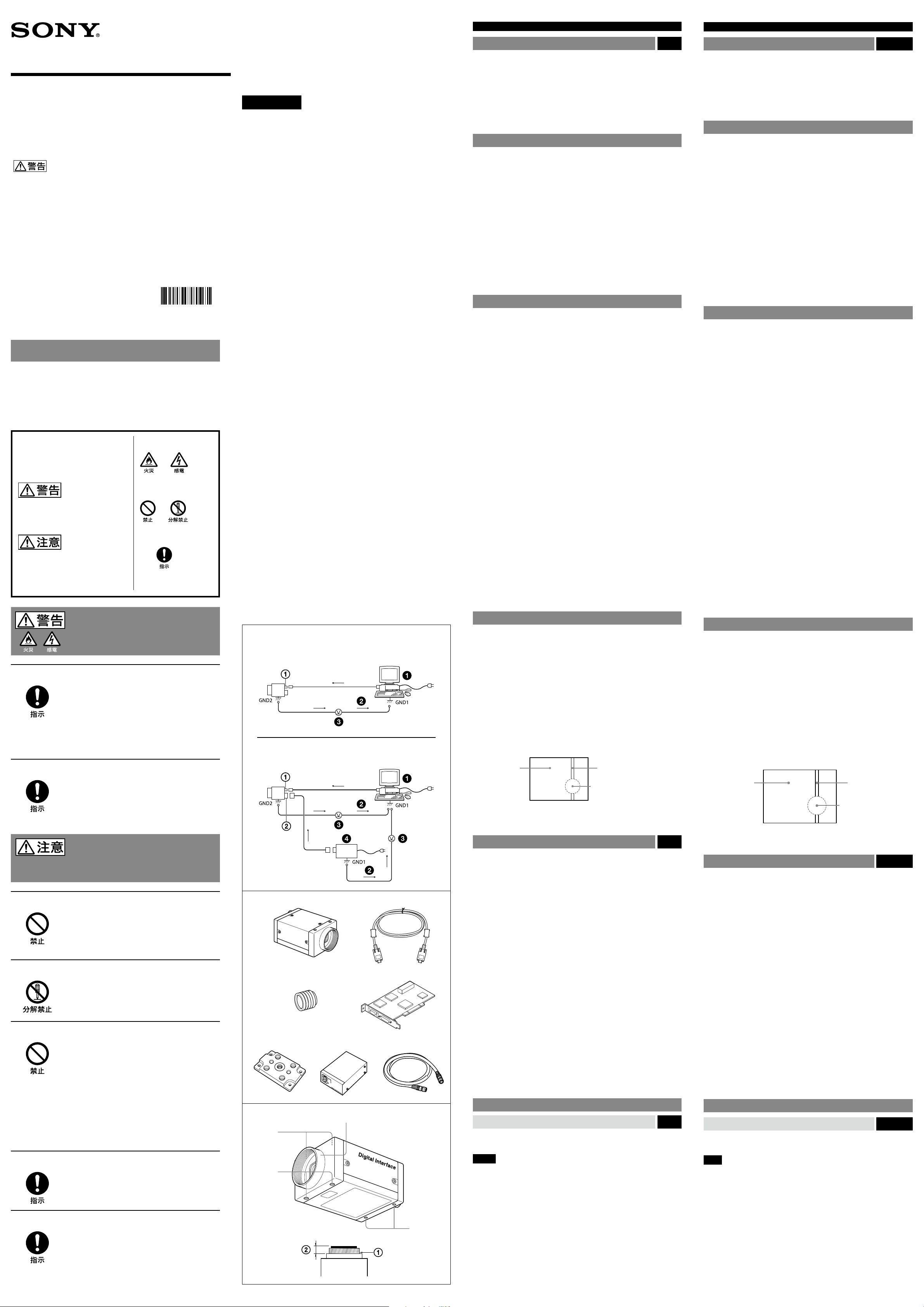
カメラ設置上のご注意
カメラ設置の際は、周辺機器を含めてカメラに接続されている各機器間で接
地電位の差が生じないようにしてください。接地電位差により故障の原因
となる場合があります。設置の都合により電位差を生ずる場合は、機器の内
いずれかひとつの機器だけを接地するようにしてください。
-1
基本構成/
IEEE1394b端子
ホスト機器(PCなど) 異常電流
接地電位差
-2
オプションの構成
電源(
12ピンI/O
DC-700
コネクター端子
)
図
A
使用上のご注意
電源について
本機の電源は、PCから
給が不足する場合には、リップルやノイズの少ない安定した電源を供給する
をご使用ください。
DC-700
IEEE1394b
ケーブルを介して供給されます。電源供
使用・保管場所
次のような場所での使用および保管はお避けください。
極端に暑い所や寒い所。適正使用温度は0〜40℃です。
激しい振動や衝撃のある所。
強力な電波を発生するテレビ、ラジオの送信所の近く。
お手入れ
レンズや光学フィルターの表面に付着したごみやほこりは、ブロアーで払っ
てください。外装の汚れは、乾いた柔らかい布でふきとります。ひどい汚れ
は、中性洗剤溶液を少し含ませた布でふきとった後、からぶきします。アル
コール、ベンジンなどは、変質したり塗料がはげることがありますので、使用
しないでください。
主な特長
XCD-V60CR/SX90CR/U100CRはRAW
モジュール、
IEEE1394b
転送速度
ことにより、デイジーチェーン接続が可能です。
XCD-V60/SX90/U100
端子
800Mbps
のデジタル出力が可能。
高画質
プログレッシブスキャン
ます。
XCD-V60CR/V60は、VGA
像出力が可能です。
によ り毎秒30フレ ームの画 像出力が可 能です。
対応の
UXGA
また、正方画素
必要がありません。
XCD -SX90CR/SX90は、SXGA
万画素
200
の採用により、画像処理時にアスペクト比の変換を行う
CCD
の採用により、高精細で高速な画像が得られ
CCD
対応の33万画素
により毎秒15フレームの画像出力が可能です。
CCD
外部トリガー機能
外部トリガー信号に同期させて任意のタイミングでシャッターを作動させ
ることができます。
電子シャッター
露光時間は豊富な設定値の中から選択可能。最適な条件で画像を取り込む
ことができます。
12ピンI/O
IEEE1394b
源を供給することができます。12ピンコネクターは、トリガー入力、ストロ
ボ出力のほか、汎用の
コネクター端子
端子からの電源供給が不足する場合、12ピンコネクターから電
にも対応しています。
I/O
低消費電力
XCD-V60CR/V60/SX90CR/SX90
XCD-U100CR/U100では3.0W(DC 12V
筐体固定
筐体固定用のネジ穴が
あります。ここでカメラモジュールを固定すれば、光軸のずれを最小限にと
どめることができます。
CCD
撮影画面に出る下記の現象は、
特有の現象で、故障ではありません。
特有の現象
基準面の含まれているフロントパネルの下部に
CCD
白点
撮像素子は非常に精密な技術で作られていますが、宇宙線などの影響
CCD
により、まれに画面上に微小な白点が発生する場合があります。
これは
また、下記の場合、白点が見えやすくなります。
高温の環境で使用するとき
ゲイン(感度)を上げたとき
スローシャッターのとき
撮像素子の原理に起因するもので故障ではありません。
CCD
スミア現象
強いスポット光やフラッシュ光などを撮影したときに、画面上に縦線や画乱
れが発生することがあります。
モニター画面
折り返しひずみ
細かい模様、線などを撮影すると、ぎざぎざやちらつきが見えることがあり
ます。
データ出力のカラーデジタルカメラ
は白黒デジタルカメラモジュールです。
IEEE1394b
CCD
端子を2つ搭載する
により毎秒90フレームの画
対応の
125
万画素
XCD -U100CR/U100
では消費電力を
入力時)に抑えました。
撮像素子(
CCD
(強いスポット光、強い反射光、
2.8W(DC 12V
Charge Coupled Device
縦に尾を引いたような
画像になる。
高輝度の被写体
フラッシュ光、太陽など)
CCD
は、
入力時)、
)
When Installing the Camera Fig. A
When you install the camera with various peripheral devices and if the devices
have dierent ground electric potential, ground only one device. In case there
is an ground electric potential dierence, the camera may be damaged.
Basic conguration /
-1
IEEE1394b connector
Host device (e.g., PC)
Ground electric potencial dierence
Optional conguration
-2
12-pin I/O connector
Abnormal electricity
Power supply unit (DC-700/700CE)
Notes on Operation
Power supply
Power is supplied to the camera module via the IEEE1394b cable connected to a
PC. If the power supply is insucient, use the DC-700/700CE that supplies stable
power with less ripple or noise.
Foreign bodies
Be careful not to spill liquids, or drop any ammable or metal objects in the
camera body.
Locations for operation and storage
Avoid operation or storage in the following places.
Extremely hot or cold locations. Recommended temperature range is 0°C to
40°C (32°F to 104°F)
Locations subject to strong vibration or shock
Near generators of strong electromagnetic radiation such as TV or radio
transmitters
Care
Use a blower to remove dust from the surface of the lens or optical lter. Clean
the exterior with a sof t, dry cloth.
If the camera is very grimy, apply a cloth soaked in a mild detergent then wipe
with a dry cloth. Do not apply organic solvents such as alcohol which may
damage the nish.
Overview
The XCD-V60CR/SX90CR/U100CR is a color digital camera module that outputs
RGB Raw Data. The XCD-V60/SX90/U100 is a monochrome digital camera
module.
IEEE1394b connector
The camera module can output a digital image with a transfer speed of
800 Mbps. Two IEEE1394b connectors allow you to make up a daisy chain
connection.
High resolution
The camera module uses a progressive scan CCD and produces high-resolution
and high-speed image output.
The XCD-V60CR/V60 has a CCD of 330,000 pixels (VGA) and outputs a digital
image at 90 frames per second. The XCD-SX90CR/SX90 has a CCD of 1,250,000
pixels (SXGA) and outputs at 30 frames per second. The XCD-U100CR/U100 has
a CCD of 2,000,000 pixels (UXGA) and outputs at 15 frames per second.
Because the CCDs are square pixel CCDs, you don’t need to convert the aspect
ratio in your image processing.
External trigger function
You can operate the shutter at any timing by synchronizing the shutter with the
external trigger signals.
Electronic shutter
You can select the exposure time from a variety of settings. This allows you to
capture an image under optimal conditions.
12-pin I/O connector
When power from the IEEE1394b connector is insucient, power is supplied
through the 12-pin connector. The 12-pin connector is also used for a trigger
input and strobe output, and as a general-purpose I/O port.
Low power consumption
The power consumption is decreased to 2.8 W for the XCD-V60CR/V60/SX90CR/
SX90 or 3.0 W for the XCD-U100CR/U100, with 12 V DC input.
Body xing
The mounting screw holes are provided in the reference plane on the lower
surface of the body, allowing mounting with the absolute minimum deviation
of the optical axis.
Phenomena Specic to CCD Image Sensors
The following phenomena that may appear in images are specic to CCD (Charge
Coupled Device) image sensors. They do not indicate malfunctions.
White ecks
Although the CCD image sensors are produced with high-precision
technologies, ne white ecks may be generated on the screen in rare cases,
caused by cosmic rays, etc.
This is related to the principle of CCD image sensors and is not a malfunction.
The white ecks especially tend to be seen in the following cases:
when operating at a high environmental temperature
when you have raised the gain (sensitivity)
when using the slow shutter
Vertical smear
When an extremely bright object, such as a strong spotlight or ashlight, is
being shot, vertical tails may be produced on the screen, or the image may be
distorted.
Monitor screen Vertical tails shown
on the image
Bright object
(e.g. strong spotlight,
strong reected light,
ashlight, the sun)
Aliasing
構成
カメラモジュールを中心とした描画システムの構成品目は、次のとおりで
す。基本構成には
メラモジュール以外はいずれも別売です。
カメラモジュール
を用いた、小型、高解像度のカメラです。
CCD
IEEE1394b
カメラモジュール裏面の
送出、制御信号の授受を行います。接続不良やカメラ、ケーブルの破損を防
ぐため、固定ねじ付きのケーブルをお使いください。
Cマウントレンズ(市販)
カメラや用途に合ったレンズをお使いください。
カメラ用画像入力ボード(市販)
ホスト機器(PCなど)の
お使いのシステムに適した
転送速度
ください。
三脚アダプター
三脚を使ってカメラモジュールを固定するとき、このアダプターをカメラモ
ジュールの底部に取り付けます。
カメラアダプター
AC
す。
カメラケーブル
800Mbps
電源から電力を供給する場合に、カメラモジュールに接続して使用しま
/25N(25 m
カメラモジュール裏面の12ピン
トリガー信号の授受を行います。
各部の名称と働き
前面/上面/底面
レンズマウント(Cマウント
マウント式のレンズや光学機器を取り付けます。
C
ご注意
マウント式のレンズとして、レンズマウント面からの飛び出し量が
C
以下のものを使用してください。
レンズマウント部
カメラ固定用補助穴(上面)
カメラ固定用基準穴(底面)
カメラモジュール固定用に高い精度で切られたネジ穴です。ここでカメラ
モジュールを固定すると、光軸のずれを最小限にとどめることができます。
◆ 詳細はユーザーズガイドをご覧ください。
の4つのネジ穴は、三脚アダプター取り付け用ネジ穴としても使用 でき
ます。三脚を使うときは、この4つのネジ穴を使って三脚アダプター
を取り付けます。
ST70I
〜
、オプションの構成には〜を使います。(カ
)
カメラケーブル(市販)
IEEE1394b
バススロットに挿入します。
PCI
IEEE1394
で使用される場合は、
VCT-ST70I
DC-700
端子に接続し、電力の供給や映像信号の
対応のボードをご使用ください。
IEEE1394b
(ソニー製)
(ソニー製)
対応のボードをご使用
CCXC-12P02N(2 m)/05N(5 m)/10N(10 m
)(ソニー製)
コネクター端子に接続し、電力の供給や
I/O
)
以下
10mm
図
B
)
図
C
10mm
VC T-
(裏面へ続く)
When ne patterns, stripes, or lines are shot, they may appear jagged or icker.
System Components Fig. B
The camera module imaging system comprises the following products.
Products to are used for the basic conguration, and to for the
optional conguration. (All the products except the camera module are
available separately.)
Camera module
This is a small-size, high-resolution, camera module using a CCD image sensor.
IEEE1394b camera cable (commercially available)
Connect this cable to the IEEE1394b connector on the rear panel of the camera
module. The power and image/control signals are transmitted through this
cable. To prevent a poor connection or damage to the camera or cable, use the
cable equipped with xing screws.
C-mount lens (commercially available)
Use an appropriate lens for the camera module and usage.
Camera module interface board (commercially available)
Install the board in a PCI bus slot of a host device such as a PC.
Select an IEEE1394 interface board to match your system.
Select an IEEE1394b interface board if you use the transfer speed of 800 Mbps.
VCT-ST70I tripod adaptor (Sony)
Attach this adaptor to the bottom of the camera module to x the camera
module to a tripod.
DC-700/700CE camera adaptor (Sony)
Connect this adaptor to the camera module to enable power supply from an
ordinary AC power source.
CCXC-12P02N (2 m, 6.6 ft)/05N (5 m, 16.4 ft)/10N (10 m, 32.8 ft)/
25N (25 m, 82 ft) camera cable (Sony)
Connect this cable to the 12-pin I/O connector on the rear panel of the camera
module. The cable is used for power supply and exchange of trigger signals.
Location and Function of Parts and Operation
Front/Top/Bottom
Lens mount (C-mount)
Attach any C-mount lens or other optical equipment.
Note
The lens must not project more than 10 mm (13/32 inch) from the lens mount.
Lens mount face
Auxiliary holes (top)
Reference holes (bottom)
These precision screw holes are for locking the camera module. Locking the
camera module into these holes secures the optical axis alignment.
For details , refer to the Technical Manual .
Four screw reference holes can be used as the tripod adapor screw holes,
too. Screw the VCT-ST70I tripod adaptor into the four screw holes when you use
a tripod.
10 mm (13/32 inch) or less
(continued on the reverse side)
Fig. C
日本語
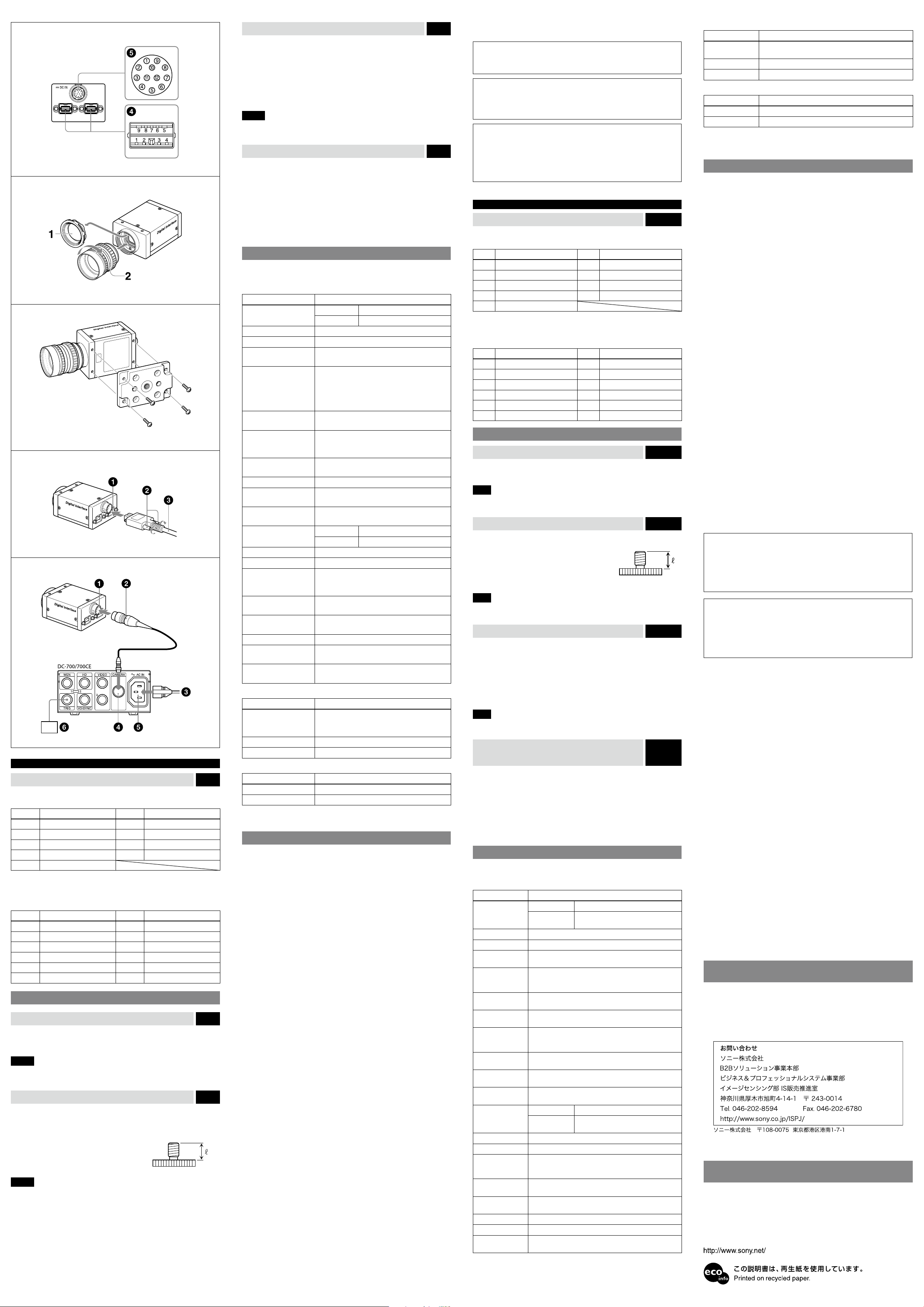
後面
IEEE1394b
市販の
IEEE1394b
ピン番号 信号 ピン番号 信号
1 TPB
2 TPB
3 TPA
4 TPA
5 TPAG
12ピンI/O
IEEE1394b
ることができます。
カメラケーブル
ピン番号 信号 ピン番号 信号
1
2
3 ISO(
4
5 GPIO出力1
6 GPIO出力1
端子
カメラケーブルを接続します。
−
+
−
+
コネクター端子
端子からの電源供給が不足する場合、この端子から電源を供給す
CCXC-12P05N
電源 (アース
電源入力
アース
ストロボ出力
などが接続できます。
) 7 GPIO入力2
) 9 GPIO出力2
−
+
6 VG
7 NC
8 VP
9 TPBG
8 GPIO出力2
10 GPIO入力1
トリガー入力
11
12 ISO(
アース
設置
レンズの取り付け
1
レンズマウントキャップをはずす。
2
レンズ(別売)を回して取り付ける。
ご注意
光学フィルターの表面に付着したごみやほこりは、市販のブロアーで払って
ください。
三脚の取り付け
三脚アダプター
脚に取り付けます。
三脚の取付部のネジは取付面からの飛び出し量()が下記のものを使用して
ください。
ISO規格
ASA規格
ネジはハンドトライバーで締めつけてください。
ご注意
三脚アダプター(別売)を取り付けるときは、三脚アダプターに付属のネジ
を使用してください。
VCT-ST70I
:
:
(別売)をカメラモジュールに取り付けてから三
4.5mm〜5.0mm
インチ
0.197
図
D
−
+
)
図
E
図
F
カメラケーブルの接続
市販の
IEEE1394b
ンターフェース端子を接続してください。接続する際は、ケーブルのコネク
ター部を持ち、固定するまでしっかりと差し込んでください。
その後、両側にある固定ねじを締め付けてください。
IEEE1394b
固定ねじ
IEEE1394b
ご注意
固定ねじがゆるむと、接続不良やカメラ、ケーブルの破損の原因となります。
固定ねじはしっかり締め付けてください。
IEEE1394b
IEEE1394b
700(別売)
給することもできます。
カメラケーブル(
〜
トリガー発生器
とカメラケーブル
12ピンI/O
電源へ
AC
CAMERA
AC IN
カメラケーブルで
端子
カメラケーブル(市販)
端子からの電源供給が不足する場合 図
端子からの電源供給が不足する場合、カ メ ラ ア ダ プ タ ー
コネクター端子
CCXC-12P05N
端子
端子
IEEE1394b
CCXC-12P05N
など)
図
G
端子とパソコンの
1394b
H
DC-
(別売)などを介して電源を供
イ
パーソナルコンピューターによるコントロール
本機はパーソナルコンピューターによりコントロールします。コントロー
ルできる機能は以下の表のとおりです。
全モデル共通機能
制御項目 内容
ゲイン カラーモデル0 〜
白黒モデル
シャッター
ブライトネス ペデスタルレベルの可変
ガンマ
トリガー ハードウェアトリガー/ソフトウェアトリガーの
ストロボ出力 レジスターにより、露光開始からのディレイと信
オートエクスポージャー 映像のレベルを検波して、ゲイン、シャッターに
オートエクスポージャー
検波枠設定
GPIO 12
メモリーショット 内蔵フレームメモリーに映像を保存し、あとで映
ISO Enable(
タート
ビデオス
)
1
/
〜 16
100,000
個のガンマテーブル(10ビット)により、ガン
1024
マカーブの自由設定が可能(
レジスター制御)、
Mode0(
をサポート
ソフトウェアトリガーはブロードキャストコマン
ドにも対応
号幅を制御
フィードバックをかけることにより、映像の平均
レベルを一定化
オートエクスポージャーの検波エリアの設定
ピンコネクターに割り当てる
像の読み出しを行う
連続モードで画像を転送開始
OneShot/MultiShot OneShot
MultiShot
DataDepth 16
CameraInitialize
メモリーチャンネル
バス同期
1394
トリガーディレイ トリガー受信時、指定した時間後にトリガーを有
パーシャルスキャン
ユーザーフリーメモリー
バルクモード メモリーチャンネルを使用して設定を変えなが
XCD-V60CR/SX90CR/U100CR(
制御項目 内容
ホワイトバランス(
モード)
ゲイン
G
オプティカルフィルター ベイヤーパターンの切り換え
Raw
XCD-V60/SX90/U100(
制御項目 内容
フィルター
3 x 3
シャープネス 映像の輪郭の強弱を調整
◆ これらの項目は、
しています。詳細はユーザーズガイドをご覧ください。
IEEE1394
ビットモード時に有効なビット長を示す
フィーチャーを初期値にリセット
PresetMemory0(
ユーザー設定チャンネル
能
バスのサイクルタイムレジスターに同期して
1394
露光のタイミングを決定
効にする
ライン
32
256
備
ら、連続して画像を取得
R、B
オートホワイトバランス/ワンプッシュホワイトバ
ランス
G
白黒モデル)のみ
3 x 3
x 24
バイトのユーザー使用可能なメモリーを装
カラーモデル)のみ
レベルの調整
ゲインの調整
フィルターの切り換え
規格のデジタルカメラプロトコル
+18 dB
0 〜 +24 dB
秒に可変
拡張機能)
IIDC
信号幅制御
Mode1(
の制御
GPIO
画像1枚を転送
指定した枚数の画像を転送
工場出荷状態)および
1 ch/15 ch
ピクセルのユニットに分割可能
切り換え可
Ver.1.31
)
に準拠
主な仕様
撮像素子
XCD-V60CR/V60/SX90CR/SX90: 1/3
XCD-U100CR/U100: 1/1.8
インターフェース仕様
IEEE1394b – 2002
出力信号フォーマット(水平/垂直
XCD-V60CR/V60: 640 x 480 (VGA)
XCD-SX90CR/SX90: 1,280 x 960 (SXGA)
XCD-U100CR/U100: 1,600 x 1,200 (UXGA)
フレームレート
XCD-V60CR/V60: 90 fps
XCD-SX90CR/SX90: 30 fps
XCD-U100CR/U100: 15 fps
転送速度
外部トリガー信号(条件
800/400 Mbps
レンズマウント
フランジバック
最低被写体照度
C
17.526 mm
XCD-V60CR/SX90CR/U100CR: 20 lx (F1.4 Gain:
XCD-V60/SX90/U100: 2 lx (F1.4 Gain: +24 dB)
ガンマ
ゲイン
XCD-V60CR/SX90CR/U100CR: 0〜+18 dB
XCD-V60/SX90/U100: 0〜+24 dB
シャッター速度
電源
IEEE1394b
消費電力
1/100,000〜16
XCD-V60CR/V60/SX90CR/SX90: 2.8 W(DC 12V
XCD-U100CR/U100: 3.0 W(DC 12V
性能保証温度
動作温度
保存温度
使用湿度
保存湿度
耐振動性
耐衝撃性
外形寸法
重量
140g
付属品
0 〜+40
20〜80% (
20〜95% (
10G (20Hz〜200Hz
70G
44 (W)×33 (H)×57.5 (D)mm
仕様および外観は改良のため予告なく変更することがありますが、ご了承く
ださい。
プログレッシブスキャン
IT CCD
)
)
パルス幅:
極性:負
振幅:
DC 5〜24V
マウント
10 μs
以上
+18 dB)
γ
= 1(LUT
トゲイン
ン
ター付きカメラケーブルより、
を供給
入力時)
−5〜+45℃
−30〜+60℃
レンズマウントキャップ
取扱説明書
で設定可)
秒、オートシャッター
カメラケーブルまたは12ピンコネク
℃
結露のない状態で
結露のない状態で
、固定用基準穴使用時
(1)
型
型
、オー
、オートゲイ
DC +8 V〜+30 V
入力時)
)
)
)
、突起部含まず
(1)
重要
機器の名称と電気定格は、底面に表示されています。
お使いになる前に、必ず動作確認を行ってください。故障その他に伴う
営業上の機会損失等は保証期間中および保証期間経過後にかかわらず、
補償はいたしかねますのでご了承ください。
この装置は、情報処理装置等電波障害自主規制協議会(
づくクラスA情報技術装置です。この装置を家庭環境で使用すると電波
妨害を引き起こすことがあります。この場合には使用者が適切な対策を
講ずるよう要求されることがあります。
定期交換部品について
本機で使用されている部品の中には有寿命部品として定期交換が必要な
もの(電解コンデンサーなど)があります。
使用環境や条件により部品の寿命は異なりますので、長期間ご使用され
る場合は定期点検をお勧めします。
◆ 詳しくはお買い上げ店にお問い合わせください。
English
VCCI
)の基準に基
Rear Fig. D
IEEE1394b connectors
Connect an IEEE1394b camera cable (not supplied) to this connector.
Pin No. Signal Pin No. Signal
1 TPB– 6 VG
2 TPB+ 7 NC
3 TPA– 8 VP
4 TPA+ 9 TPBG
5 TPAG
12-pin I/O connector
When power from the IEEE1394b connector is insucient, power is supplied
through this connector.
Connect a camera cable such as the CCXC-12P05N to this connector.
Pin No. Signal Pin No. Signal
1 Power GND 7 GPIO IN 2
2 Power IN 8 GPIO OUT 2-
3 ISO GND 9 GPIO OUT 2+
4 Strobe OUT 10 GPIO IN 1
5 GPIO OUT 1- 11 Trigger IN
6 GPIO OUT 1+ 12 ISO GND
Installation
Fitting the lens
1 Remove the lens mount cap.
2 Screw in the lens (not supplied), and turn it until it is secured.
Note
Clean the optical lter with a commercially available blower brush to remove
dust.
Using a tripod
To use the tripod, install the VCT-ST70I tripod adaptor (not supplied) on the
camera module.
Use a tripod screw with a protrusion () extending
from the installation sur face, as follows:
ISO standard: Length 4.5 mm to 5.0 mm
ASA standard: Length 0.197 inches
Tighten the tripod screws using a hand screwdriver.
Note
When you install the tripod adaptor, use the screws supplied with the tripod
adaptor.
Connecting the camera cable
Connect a commercially available IEEE1394b camera cable to the IEEE1394b
connector and the 1394b interface connector of your PC. When you connect
the cable, insert the cable connector into the IEEE1394b connector until it snaps
into place, holding it. Then, tighten the xing screws placed on both sides of the
cable connector.
IEEE1394b connector
Fixing screws
IEEE1394b camera cable (not supplied)
Note
Loose xing screws may cause a poor connection or damage to the camera or
cable. Be sure to tighten the xing screws.
When power supply from the IEEE1394b
connector is insucient
Power can be supplied to the camera module via the DC-700/700CE camera
adaptor (optional) and a camera cable such as CCXC-12P05N (optional) if power
supply from the IEEE1394b connector is insucient.
12-pin I/O connector
Camera cable (e.g. CCXC-12P05N)
to AC power source
CAMERA connector
AC IN connector
Trigger generator
Fig. E
Fig. F
Fig. G
Fig. H
Controlling the Camera from Your PC
You can control the camera from your PC. The following table shows the control
functions.
Functions common to all models
Control function Description
Gain Color model 0 to +18 dB
Black and white
model
Shutter Setting the shutter speed between 1/100,000 and 16 sec.
Brightness Pedestal level adjustable
Gamma Customizing the gamma curve using 1,024 gamma tables
Trigger Mode 0 (control by register) and Mode 1 (control by pulse
Strobe Out Setting the delay from the exposure start and the pulse
AutoExposure Keeping a constant average image level by the image
AutoExposure
Detection Frame
Setting
GPIO Assigning GPIO (General-Purpose Input/Output) to the
MemoryShot Saving an image to the built-in frame memor y and
ISO Enable (Video
Start)
OneShot/
MultiShot
DataDepth Indicating the eective bit length in 16-bit mode
CameraInitialize Resetting the camera to the default features
MemoryChannel PresetMemory0 (factory default status) and 1 user
1394 Bus
Synchronization
TriggerDelay Specifying the delay time after which the received
PartialScan Partition by a unit of 32 lines x 24 pixels available
UserFreeMemory A 256-byte user available memory provided
Bulk Mode Acquiring images continuously by changing the settings
(10 bits) (IIDC extended function)
width) supported for hardware trigger/software trigger
Broadcast commands supported for software trigger
width by register value
level detection and feedback to gain and shutter
Setting the detection area for Auto Exposure
12-pin connector
reading the saved image from the memory
Starts transmitting an image in continuous mode
OneShot Transmitting an image
MultiShot
available memory channel / 15 user available memory
channels selectable
Dening the exposure timing in synchronization with
the cycle time register of 1394 bus
trigger becomes eective
in memory channels
0 to +24 dB
Transmitting the specied number of
images
XCD-V60CR/SX90CR/U100CR (color models) only
Control function Description
WhiteBalance (Raw
mode)
G Gain Adjusting the G gain
OpticalFilter Switching the Bayer pattern
XCD-V60/SX90/U100 (black and white models) only
Control function Description
3 x 3 Filter Switching the 3 x 3 lter
Sharpness Adjusting the image contour strength
These contro l items comply with Digita l Camera Protocol, Ver. 1.31, of the IEEE1394 Standard.
For more detai ls, refer to the Technical Man ual.
Adjusting the R and B levels individually
Auto white balance, One Push white balance available
Specications
Pickup device Progressive scan IT CCD
XCD-V60CR/V60/SX90CR/SX90: 1/3 type
XCD-U100CR/U100: 1/1.8 type
Interface IEEE1394b – 2002
Output signal format (horizontal/vertical)
XCD-V60CR/V60: 640 x 480 (VGA)
XCD-SX90CR/SX90: 1,280 x 960 (SXGA)
XCD-U100CR/U100: 1,600 x 1,200 (UXGA)
Frame rate XCD-V60CR/V60: 90 fps
XCD-SX90CR/SX90: 30 fps
XCD-U100CR/U100: 15 fps
Transfer speed 800/400 Mbps
External trigger signal (conditions)
Pulse width: 10 μs or more
Polarity: Negative
Amplitude: 5 to 24 V DC
Lens mount C-mount
Flange back 17.526 mm
Minimum illumination XCD-V60CR/SX90CR/U100CR: 20 lx (F1.4, Gain: +18
XCD-V60/SX90/U100: 2 lx (F1.4, Gain: +24 dB)
Gamma γ= 1 (selectable by LUT)
Gain XCD-V60CR/SX90CR/U100CR: 0 to +18 dB, Auto
XCD-V60/SX90/U100: 0 to +24 dB, Auto gain
Shutter speed 1/100,000~16 seconds, Auto shutter
Power +8 V to +30 V DC from IEEE1394b camera cable or
Power consumption XCD-V60CR/V60/SX90CR/SX90: 2.8 W (12 V DC
XCD-U100CR/U100: 3.0 W (12 V DC input)
Performance guaranty temperature
0 to +40°C (32 to 104°F)
Operating temperature –5 to +45°C (23 to 113°F)
Storage temperature –30 to +60°C (–22 to 140°F)
Operating relative humidity
20 to 80% (no condensation)
Storage relative humidity 20 to 95% (no condensation)
Vibration resistance 10 G (20 Hz to 200 Hz, at using the reference holes)
Shock resistance 70 G
External dimension (w/h/d) 44 × 33 × 57.5 mm (13/4 × 13/16 × 23/8 inches), not
Mass 140 g (4 oz)
Accessories Lens mount cap (1)
Operating Instructions (1)
Design and specications are subject to change without notice.
IMPORTANT
The nameplate is located on the bottom.
Note
Always verify that the unit is operating properly before use. SONY WILL
NOT BE LIABLE FOR DAMAGES OF ANY KIND INCLUDING, BUT NOT LIMITED
TO, COMPENSATION OR REIMBURSEMENT ON ACCOUNT OF THE LOSS OF
PRESENT OR PROSPECTIVE PROFITS DUE TO FAILURE OF THIS UNIT, EITHER
DURING THE WARRANTY PERIOD OR AFTER EXPIRATION OF THE WARRANTY,
OR FOR ANY OTHER REASON WHATSOEVER.
Regular parts replacement
Some of the parts that make up this product (electrolytic condenser, for
example) need replacing regularly depending on their life expectancies.
The lives of parts dier according to the environment or condition in which
this product is used and the length of time it is used, so we recommend
regular checks.
Consult the dealer from whom you bought it for details.
dB)
gain
camera cable with 12-pin connector
input)
including projecting parts
ユーザーズガイドについて
この取扱説明書は本 機の基本的 な機能と使 用方法につ いて記載しており
ます。
より詳しい情報をお 知りになり たい方は「 ユーザーズ ガイド」をご覧くだ
さい。
「ユーザーズガイド」については営業担当者にお問い合わせください。
About the Technical Manual
The Operating Instructions describe the functions and use of this product.
For more details, see the
representative about the
Technical Manual
Technical Manual
. Please ask your sales
.
 Loading...