

Sony XCD-V50CR User Manual
3-872-733-03 (1)
Owner’s Record
日本語日本語
日本語
日本語日本語
English
Digital Video Camera Module
取扱説明書
Operating Instructions
お買い上げいただきありがとうございます。
電気製品は、安全のための注意事項を守らないと、けがをし
たり周辺の物品に損害を与えることがあります。
この取扱説明書には、事故を防ぐための重要な注意事項と製品の取り扱い
かたを示してあります。この取扱説明書をよくお読みのうえ、製品を安全
にお使いください。お読みになったあとは、いつでも見られるところに必
ず保管してください。
XCD-V50CR
XCD-V50
2005 Sony Corporation Printed in Japan
安全のために
ソニー製品は安全に充分に配慮して設計されています。しかし、まちがった
使いかたをすると、火災や感電などにより死亡や大けがなど人身事故につな
がることがあり、危険です。
事故を防ぐために次のことを必ずお守りください。
• 安全のための注意事項を守る。
• 長期間、安全にお使いいただくために、定期点検をすることをおすすめ
します。点検の内容や費用については、お買い上げ店にご相談ください。
• 故障したら使わずに、お買い上げ店にご連絡ください。
警告表示の意味
この取扱説明書および製品では、次のよ
うな表示をしています。表示の内容をよ
く理解してから本文をお読みください。
この表示の注意事項を守らないと、火災
やその他の事故によりけがをしたり周
辺の物品に損害を与えたりすることが
あります。
(Color model)
(Black and white model)
行為を禁止する記号
行為を指示する記号
The model and serial numbers are located on the bottom. Record
the serial number in the space provided below. Refer to these
numbers whenever you call upon your Sony dealer regarding this
product.
Model No. _____________ Serial No. ______________
WARNING
To reduce the risk of fire or electric shock, do
not expose this apparatus to rain or moisture.
To avoid electrical shock, do not open the
cabinet. Refer servicing to qualified personnel
only.
IMPORTANT
The nameplate is located on the bottom.
For the customers in the U.S.A.
This equipment has been tested and found to comply with the limits
for a Class B digital device, pursuant to Part 15 of the FCC Rules.
These limits are designed to provide reasonable protection against
harmful interference in a residential installation. This equipment
generates, uses, and can radiate radio frequency energy and, if not
installed and used in accordance with the instructions, may cause
harmful interference to radio communications. However, there is no
guarantee that interference will not occur in a particular installation.
If this equipment does cause harmful interference to radio or
television reception, which can be determined by turning the
equipment off and on, the user is encouraged to try to correct the
interference by one or more of the following measures:
– Reorient or relocate the receiving antenna.
– Increase the separation between the equipment and receiver.
– Connect the equipment into an outlet on a circuit different from
that to which the receiver is connected.
– Consult the dealer or an experienced radio/TV technician for
help.
You are cautioned that any changes or modifications not expressly
approved in this manual could void your authority to operate this
equipment.
All interface cables used to connect peripherals must be shielded in
order to comply with the limits for a digital device pursuant to
Subpart B of Part 15 of FCC Rules.
This device complies with part 15 of the FCC Rules. Operation is
subject to the following two conditions: (1) this device may not
cause harmful interference, and (2) this device must accept any
interference received, including interference that may cause
undesired operation.
For customers in Canada
This Class B digital apparatus complies with Canadian ICES-003.
Pour les clients au Canada
Cet appareil numérique de la classe B est conforme à la norme
NMB-003 du Canada.
For customers in Europe
This camera is not intended for use in security applications in the
meaning of the European standard series EN 50132 (Alarm
systems - CCTV surveillance systems for use in security
applications).
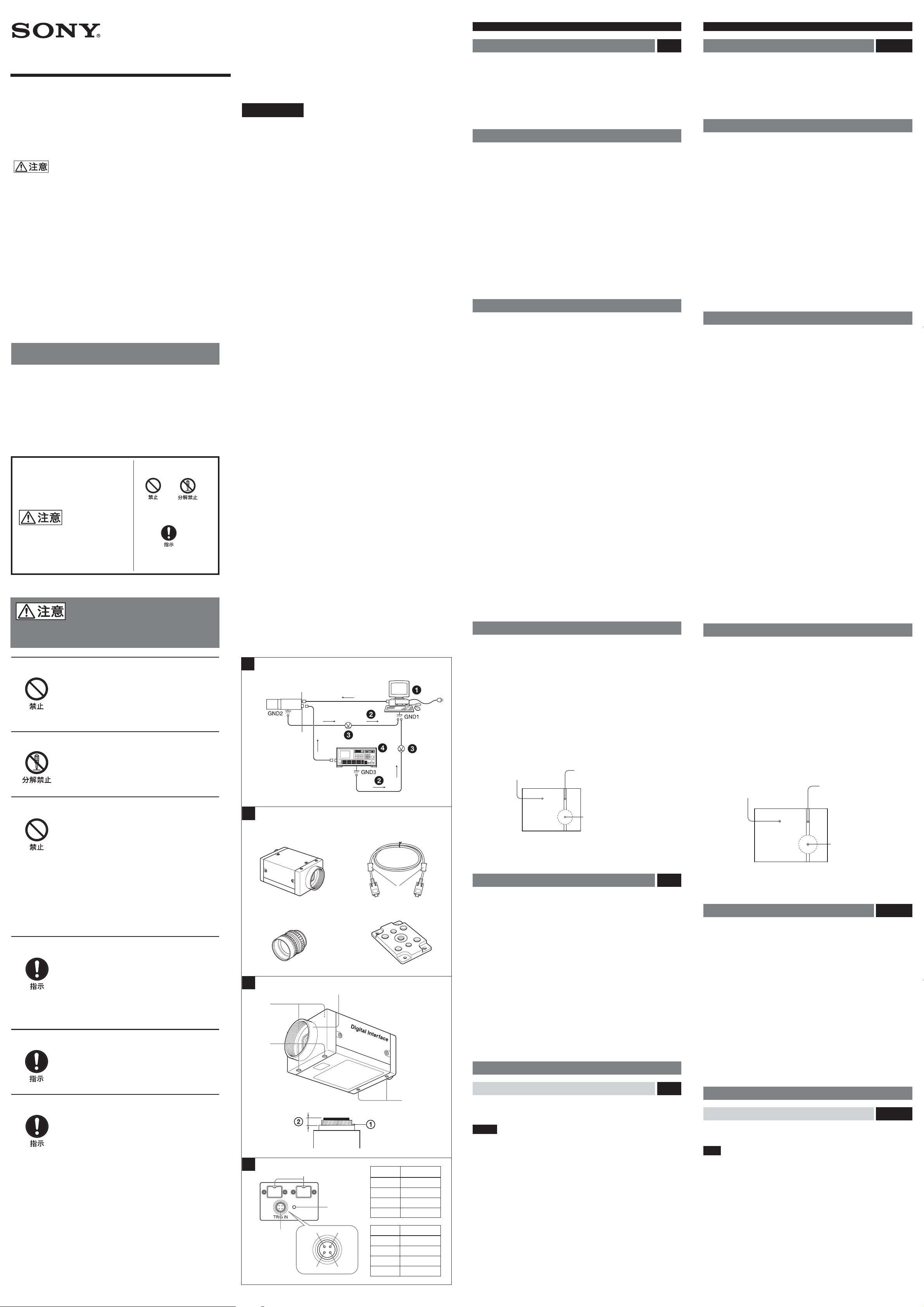
カメラ設置上のご注意 図
カメラ設置の際は、周辺機器を含めてカメラに接続されている各機器間で接
地電位の差が生じないようにしてください。接地電位差により故障の原因と
なる場合があります。設置の都合により電位差を生ずる場合は、機器の内い
ずれかひとつの機器だけを接地するようにしてください。
1
IEE1394b
1 ホスト機器(
3 接地電位差 4 トリガー信号発生器
端子 2
など) 2 異常電流
PC
TRIG IN
端子
A
使用上のご注意
放熱
内部の温度上昇を避けるため、動作中は布などで包まないでください。
使用・保管場所
次のような場所での使用および保管はお避けください。
• 極端に暑い所や寒い所。適正使用温度は
• 湿気、ほこりの多い所。
• 雨にあたる所。
• 激しい振動のある所。
• 強力な電波を発生するテレビ、ラジオの送信所の近く。
0〜40
℃です。
お手入れ
レンズや光学フィルターの表面に付着したごみやほこりは、ブロアーで払っ
てください。外装の汚れは、乾いた柔らかい布でふきとります。ひどい汚れ
は、中性洗剤溶液を少し含ませた布でふきとった後、からぶきします。アル
コール、ベンジンなどは、変質したり塗料がはげることがありますので、使
用しないでください。
主な特長
XCD-V50CRはRAW
で、
XCD-V50はIEEE1394b
現した白黒デジタルビデオカメラモジュールです。
IEEE1394b
転送速度
IEEE1394b
なりました。
高画質
VGA
す。また、正方画素
行う必要がありません。
外部トリガー機能
外部トリガー信号に同期させて任意のタイミングでシャッターを作動させる
ことができます。
電子シャッター
露光時間は豊富な設定値の中から選択可能。最適な条件で画像を取り込むこ
とができます。
エクスポージャーアウト端子
Exposure OUT
れにより、外部光源の制御が可能となります。
小型化
筐体サイズを
低消費電力
消費電力を2Wに抑えました。
筐体固定
筐体固定用のネジ穴が
ります。ここでカメラモジュールを固定すれば、光軸のずれを最小限にとど
めることができます。
800Mbps
端子を2つ搭載することにより、デイジーチェーン接続が可能と
対応の33万画素の高画素
XC-ST
データ出力のカラーデジタルビデオカメラモジュール
端子によりデジタル信号による映像出力を実
端子
に対応。毎秒60フレームの画像のデジタル出力が可能。
を採用。きめ細やかな画像を再現しま
CCD
の採用により、画像処理時にアスペクト比の変換を
CCD
端子を搭載することにより露光時間を示す信号を出力。こ
シリーズと同一サイズに小型化しました。
基準面の含まれているフロントパネルの下部にあ
CCD
When installing the camera Fig. A
When you install the camera with various peripheral devices and if the
devices have different ground electric potential, ground only one device. In
case there is an ground electric potential difference, the camera may be
damaged.
1 IEE1394b connector 2 TRIG IN connector
1 Host device (e.g., PC) 2 Abnormal electricity
3 Ground electric potencial difference 4 Trigger signal generator
Notes on Operation
Foreign bodies
Be careful not to spill liquids, or drop any flammable or metal objects in the
camera body.
Heat radiation
Do not wrap the camera in cloth or other material while in operation. There
is a danger of overheating.
Locations for operation and storage
Avoid operation or storage in the following places.
• Extremely hot or cold locations. Recommended temperature range is 0°C
to 40°C. (32°F to 104°F)
• Humid or dusty locations
• Locations exposed to rain
• Locations subject to strong vibration
• Near generators of strong electromagnetic radiation such as TV or radio
transmitters.
Care
Use a blower to remove dust from the surface of the lens or optical filter.
Clean the exterior with a soft, dry cloth.
If the camera is very grimy, apply a cloth soaked in a mild detergent then
wipe with a dry cloth. Do not apply organic solvents such as alcohol which
may damage the finish.
Overview
The XCD-V50CR is a color digital video camera module. This camera
module outputs RGB Raw Data.
The XCD-V50 is a monochrome digital video camera module. The camera
module outputs digital images (signals) from the IEEE1394b connectors.
IEEE1394b connector
The transmission speed is 800Mbps. The camera module can output a
digital image at 60 frames per second.
The camera module is equipped with two IEEE1394b connectors. This
allows you to make up daisy chain connection.
High resolution
The camera module has a high-resolution CCD of 330,000 pixels. Because
the CCDs are square pixel CCDs, you don’t need to convert the aspect ratio
in your image processing.
External trigger function
You can operate the shutter at any timing by synchronizing the shutter with
the external trigger signals.
Electronic shutter
You can select the exposure time from a variety of settings. This allows you
to capture an image under optimal conditions.
Exposure OUT connector
The Exposure OUT connector outputs a signal indicating the exposure time.
This allows you to control the external light source.
Compact size
The body size is same size as the XC-ST series camera modules which are
the compact size.
Low power consumption
The power consumption is decreased to 2 W.
Body fixing
These mounting screw holes are provided in the reference plane on the
lower surface of the body, allowing mounting with the absolute minimum
deviation of the optical axis.
下記の注意事項を守らないと、けがをしたり周辺の物品に損害
を与えることがあります。
内部に水や異物を入れない
水や異物が入ると、火災の原因となります。
万一、水や異物が入ったときは、すぐに本機が接続され
ている電源供給機器の電源を切り、DC電源ケーブルや
接続ケーブルを抜いて、お買い上げ店にご相談くださ
い。
分解しない、改造しない
分解や改造をすると、火災やけがの原因となります。
点検および修理は、お買い上げ店にご依頼ください。
カメラケーブルを傷つけない
カメラケーブルを傷つけると、火災や故障の原因となる
ことがあります。次の項目をお守りください。
• 設置時に、製品と壁やラック、棚などの間に、はさみ込
まない。
• カメラケーブルを加工したり、傷つけたりしない。
• 重いものをのせたり、引っ張ったりしない。
• 熱器具に近づけたり、加熱したりしない。
• カメラケーブルを抜くときは、必ずプラグを持って抜
く。
芯線の露出や断線などでカメラケーブルが傷んだら、お
買い上げ店に交換をご依頼ください。そのまま使用する
と、火災の原因となります。
設置は確実に
設置については、必ずお買い上げ店にご相談ください。
壁面や天井などへの設置は、本機と取り付け金具を含む
重量に充分耐えられる強度があることをお確かめくだ
さい。充分な強度がないと、落下して、大けがの原因とな
ります。
また、1年に1度は、取り付けがゆるんでいないことを点
検してください。
指定された専用機器に接続する
指定された以外の機器を接続すると、火災や故障の原因
となることがあります。
A
カメラ/Camera
1
2
B
12
5
3
4
C
1
2
3
CCD
撮影画面に出る下記の現象は、
Device
特有の現象
撮像素子(
CCD
)特有の現象で、故障ではありません。
Charge Coupled
白点
撮像素子は非常に精密な技術で作られていますが、宇宙線などの影響に
CCD
より、まれに画面上に微小な白点が発生する場合があります。
これは
また、下記の場合、白点が見えやすくなります。
高温の環境で使用するとき
•
ゲイン(感度)を上げたとき
•
撮像素子の原理に起因するもので故障ではありません。
CCD
スミア現象
強いスポット光やフラッシュ光などを撮影したときに、画面上に縦線や画乱
れが発生することがあります。
モニター画面
縦に尾を引いたような
画像になる。
高輝度の被写体
(強いスポット光、強い反射光、
フラッシュ光、太陽など)
折り返しひずみ
細かい模様、線などを撮影すると、ぎざぎざやちらつきが見えることがあり
ます。
構成 図
デジタルビデオカメラモジュール
の構成品目は、次のとおりです。
1 カラーデジタルビデオカメラモジュール
タイプ
VGA
ラーデジタルビデオカメラです。
白黒デジタルビデオカメラモジュール
タイプ
VGA
2
IEEE1394b
カメラモジュール裏面の
の送出、制御信号の授受を行います。
3Cマウントレンズ(別売)
推奨レンズ:
4 三脚アダプター
三脚を使ってカメラモジュールを固定するとき、このアダプターをカメラモ
ジュールの底部に取り付けます。
5 フェライトクランプ(付属)
を用いた、小型の
CCD
を用いた、小型の白黒デジタルビデオカメラです。
CCD
カメラケーブル(付属)
IEEE1394b
VCL-08YM/12/YM16Y-M/25Y-M/50Y-M
VCT-ST70I
XCD-V50CR/V50
XCD-V50CR
モード出力(ベイヤー配列)カ
RAW
XCD-V50
端子に接続し、電力の供給や映像信号
(別売)
を中心としたシステム
B
各部の名称と働き
Phenomena specific to CCD image sensors
The following phenomena that may appear in images are specific to CCD
(Charge Coupled Device) image sensors. They do not indicate
malfunctions.
White flecks
Although the CCD image sensors are produced with high-precision
technologies, fine white flecks may be generated on the screen in rare
cases, caused by cosmic rays, etc.
This is related to the principle of CCD image sensors and is not a
malfunction.
The white flecks especially tend to be seen in the following cases:
• when operating at a high environmental temperature
• when you have raised the gain (sensitivity)
Vertical smear
When an extremely bright object, such as a strong spotlight or flashlight, is
being shot, vertical tails may be produced on the screen, or the image may
be distorted.
Monitor screen
Vertical tails shown on
the image.
Bright object
(e.g. strong spotlight,
strong reflected light,
flashlight, the sun)
Aliasing
When fine patterns, stripes, or lines are shot, they may appear jagged or
flicker.
System Components Fig. B
The Digital Video Camera Module XCD-V50CR/V50 system comprises the
following optional products.
1 XCD-V50CR Color Digital Video Camera Module
This is a small-size, RAW mode output (Bayer pattern) color digital video
camera module using a VGA CCD image sensor.
XCD-V50 Black-and-White Digital Video Camera Module
This is a small-size, monochrome digital video camera module using a
VGA CCD image sensor.
2 IEEE1394b camera cable (supplied)
Connect this cable to the IEEE1394b connector located at the rear of
camera module. The power and image/control signals are transmitted
through this cable.
3 C-mount lens (not supplied)
Recommended lens: VCL-08YM/12/YM16Y-M/25Y-M/50Y-M
4 VCT-ST70I tripod adaptor (not supplied)
This attaches to the bottom of the camera module to fix the camera module
to a tripod.
5 Ferrite clamps (supplied)
指定された接続ケーブルを使う
この取扱説明書に記されている付属の接続ケーブルを
使わないと、火災や故障の原因となることがあります。
D
6
4
5
41
3
前面/上面/底面 図
3
ピン番号 信号名称
1 EXPO-OUT
2 TRG-GND
3 TRG-IN
4NC
Pin No. Signal
1 EXPO-OUT
2 TRG-GND
2
3 TRG-IN
4NC
1 レンズマウント(Cマウント
マウント式のレンズや光学機器を取り付けます。
C
ご注意
マウント式のレンズとして、レンズマウント面からの飛び出し量が
C
下のものを使用してください。
1 レンズマウント部 2
2 カメラ固定用補助穴(上面)
3 カメラ固定用基準穴(底面)
カメラモジュール固定用に高い精度で切られたネジ穴です。ここでカメラモ
ジュールを固定すると、光軸のずれを最小限にとどめることができます。
◆ 寸法など詳しくは裏面右下の「ユーザーズガイドについて」をご覧ください。
3の4つのねじ穴は、三脚アダプター取り付け用ネジ穴としても使用できま
す。三脚を使うときは、この4つのネジ穴を使って三脚アダプター
を取り付けます。
ST70I
)
7mm
以下
7mm
VCT-
C
Location and Function of Parts and Operation
Front/Top/Bottom Fig. C
1 Lens mount (C-mount)
以
Attach any C-mount lens or other optical equipment.
Note
The lens must not project more than 7 mm (9/32 inch) from the lens mount.
1 Lens mount face 2 7 mm (9/32 inch) or less
2 Auxiliary holes (Top)
3 Reference holes (bottom)
These precision screw holes are for locking the camera module. Locking
the camera module into these holes secures the optical axis alignment.
For details on dimensions, etc., see “About the Technical Manual” on the lower right of
the back side.
Four screw reference holes of 3 can be used as the tripod adapor screw
holes, too. Screw the tripod adaptor VCT-ST70I into the four screw holes
when you use a tripod.
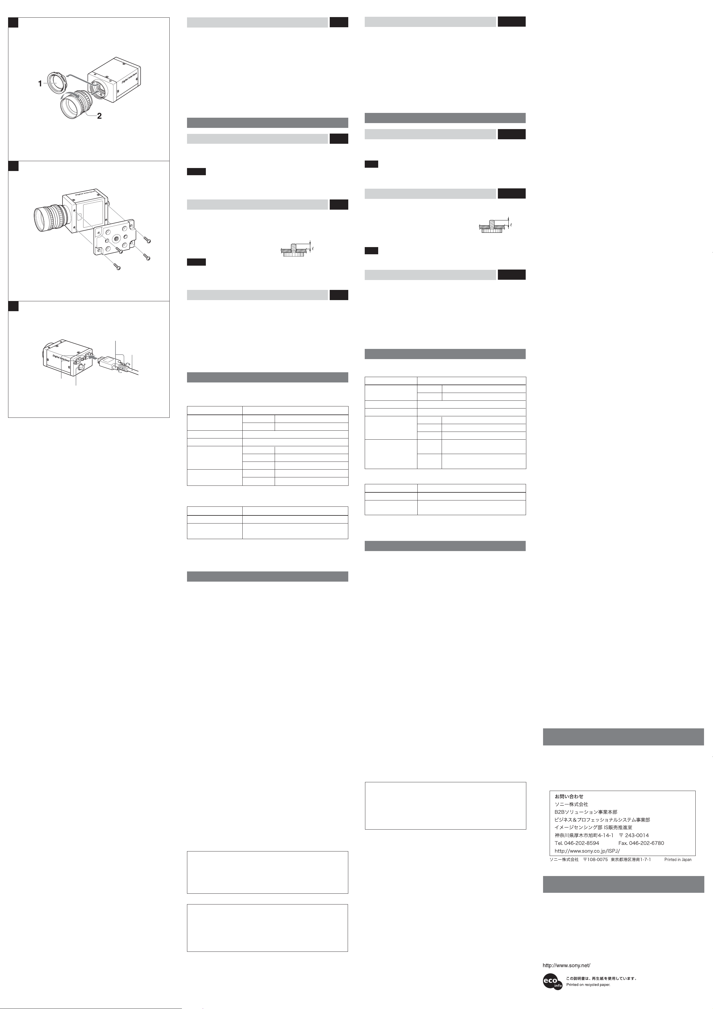
E
後面 図
D
Rear Fig. D
F
G
1
2
3
4
4
IEEE1394b
付属の
IEEE1394b
5 パイロットランプ
カメラモジュールの作動状況を示すランプです。
消灯時:カメラ電源
緑色点灯時:カメラ電源ON/画像出力
橙色点灯時:カメラ電源ON/画像出力
6
TRIG IN
端子
外部のトリガー信号発生器のトリガー出力端子と接続します。
外部トリガーを
端子
カメラケーブルを接続します。
OFF
OFF
ON
(トリガー)/
OFF
Exposure OUT
に設定した時は、露光期間を示す信号が出力されます。
(エクスポージャーアウト)
設置
レンズの取り付け 図
1 レンズマウントキャップをはずす。
2 レンズ(別売)を回して取り付ける。
ご注意
光学フィルターの表面に付着したごみやほこりは、市販のブロアーで払って
ください。
三脚の取り付け 図
三脚アダプター
脚に取り付けます。
三脚の取付部のネジは取付面からの飛び出し量(4)が下記のものを使用して
ください。
ISO
ASA
ご注意
三脚アダプター(別売)を取り付けるときは、三脚アダプターに付属のネジ
を使用してください。
VCT-ST70I
規格 4:
規格 4:
(別売)をカメラモジュールに取り付けてから三
4.5mm±0.2mm
インチ
0.197
カメラケーブルの接続 図
付属の
IEEE1394b
ターフェース端子を接続してください。接続する際は、ケーブルのコネク
ター部を持ち、固定するまでしっかりと差し込んでください。
その後、両側にある固定ねじを締め付けてください。
1
IEEE1394b
2
TRIG IN
3 固定ねじ
4
IEEE1394b
カメラケーブルで
端子
端子
カメラケーブル(付属)
IEEE1394b
とパソコンの
1394b
E
F
G
イン
パーソナルコンピューターによるコントロール
本機はパーソナルコンピューターによりコントロールします。コントロール
できる機能は以下の表のようになっています。
制御項目 内容
フレームレート
転送速度
ゲイン
シャッター速度
外部トリガー
XCD-V50CR
制御項目 内容
ホワイトバランス
ヒュ−
にはさらに以下の機能があります。
Mono 8 60/30/15 fps
Mono 16 30/15 fps
800M/400M bps
0 〜 +18 dB
15 fps
30 fps
60 fps
Mode 0
Mode 1
に対するRとBのゲインを調整します。
G
でホワイトバランスがとれない場合、
RとB
ヒュ−でGのゲインを調整します。
/
100000
1
時
/
100000
1
時
/
100000
露光時間をレジスターで設定
露光時間をトリガー幅で制御
1
時
1
〜
秒
/15
1
〜
秒
/30
1
〜
秒
/60
4 IEEE1394b connectors
Connect the IEEE1394b camera cable (supplied) to this connector.
5 Pilot lamp
This lamp indicates the camera module operation states:
OFF: Camera power OFF
Green: Camera power ON/Video signal output OFF
Orange: Camera power ON/Video signal output ON
6 TRIG IN (Trigger)/Exposure OUT connector
Connect the trigger signal generator (trigger output connector) to this
connector.
When the external trigger function is set to OFF, a signal indicating the
exposure time is output.
Installation
Fitting the lens Fig. E
1 Remove the lens mount cap.
2 Screw in the lens (not supplied), and turn it until it is secured.
Note
Clean the optical filter with a commercially available blower brush to remove
dust.
Using a tripod Fig. F
To use the tripod, install the tripod adaptor VCT-ST70I (not supplied) on the
camera module.
Use a tripod screw with a protrusion (4) extending
from the installation surface, as follows:
ISO standard: Length 4.5 mm ±0.2 mm
ASA standard: Length 0.197 inches
Note
If you install a tripod adapter (not supplied), use the screws provided.
Connecting the camera cable Fig. G
Connect the IEEE1394b camera cable to the IEEE1394b connector and the
1394b interface connector of your computer. When you connect the cable,
insert the cable connector into the IEEE1394b connector until it snaps into
place, holding it. Then, tighten the fixing screws placed on both sides of the
cable connector.
1 IEEE1394b connector
2 TRIG IN connector
3 Fixing screws
4 IEEE1394b camera cable (supplied)
Controlling the camera from your PC
You can control the camera from your PC. The following table shows the
control functions.
Control functions Description
Frame rate Mono 8 60/30/15 fps
Mono 16 30/15 fps
Transmission speed 800M/400M bps
Gain 0 to +18 dB
Shutter speed 15 fps
30 fps
60 fps
External trigger Mode 0 Setting the exposure time by resister
function value
Mode 1 Setting the exposure time by trigger
The XCD-V50CR also offers the following functions.
Control functions Description
White balance R and B gain can be adjusted with respect to G.
Hue If white balance cannot be obtained using R and
B, G gain can be adjusted using Hue.
These control items comply with Digital Camera Protocol, Ver. 1.31, of the IEEE1394
Serial Digital Bus Standard. For more details, refer to the Technical Manual.
1
/100000 to 1/15 seconds
1
/100000 to 1/30 seconds
1
/100000 to 1/60 seconds
pulse (width)
◆ これらの項目は、シリアルデジタルバス規格
トコル
Ver.1.31
に準拠しています。詳細はユーザーズガイドをご覧ください。
IEEE1394
のデジタルカメラプロ
主な仕様
撮像素子 プログレッシブスキャン
有効画素数
インターフェース仕様
出力信号フォーマット 標準
フレームレート
転送速度
外部トリガー信号(条件)
レンズマウント
フランジバック
最低被写体照度
659×494
IEEE1394b – 2002
60/30/15 fps
800M/400M bps
パルス幅
極性
振幅
マウント
C
17.526 mm
XCD-V50CR : 20 lx (F0.95、Gain: +18dB)
(水平/垂直)
640×480
:10μs
負
:
: TTL
(水平/垂直)
XCD-V50 : 4 lx (F0.95
ガンマ γ=
ゲイン
シャッター速度
電源
1
0〜+18 dB
1
/
100000
1
〜
IEEE1394b
秒
/15
カメラケーブルより
DC +8V〜+30V
消費電力
動作温度 −5〜+45℃
保存温度 −30〜+60℃
使用湿度
保存湿度
耐振動性
耐衝撃性
外形寸法
重量
付属品
仕様および外観は改良のため予告なく変更することがありますが、ご了承く
ださい。
重要
機器の名称と電気定格は、底面に表示されています。
2.0W
20〜80% (
20〜95% (
結露のない状態で
結露のない状態で
10G (20Hz〜200Hz
70G
44 (W)×29 (H)×57.5 (D)mm
120g
IEEE1394b
レンズマウントキャップ
トリガー入力用
取扱説明書
カメラケーブル
4pin
(1)
CCD
以上
レベル
、
Gain: +18dB)
を供給
)
)
、固定用基準穴使用時
(1)
(1)
コネクター(1)
)
Specifications
Pickup device Progressive scan CCD
Effective picture elements
Interface IEEE1394b-2002
Output signal format Standard: 640 × 480 (horizontal/vertical)
Frame rate 60/30/15 fps
Transfer speed 800M/400M bps
External trigger signal (conditions)
Lens mount C-mount
Flange back 17.526 mm
Minimum illumination XCD-V50CR : 20 lx (F0.95, Gain: +18 dB)
Gamma γ = 1
Gain 0 to +18 dB
Shutter speed
Power DC +8 V to +30 V (from IEEE1394b camera
Power consumption 2.0 W
Operating temperature –5 to +45°C (23 to 113°F)
Storage temperature –30 to +60°C (–22 to 140°F)
Operating relative humidity
Storage relative humidity
Vibration resistance 10 G (20 Hz to 200 Hz, at using the reference
Shock resistance 70 G
External dimension (w/h/d)
Mass 120 g (4 oz)
Accessories IEEE1394b camera cable (1)
Design and specifications are subject to change without notice.
Regular parts replacement
Some of the parts that make up this product (electrolytic condenser, for
example) need replacing regularly depending on their life expectancies.
The lives of parts differ according to the environment or condition in
which this product is used and the length of time it is used, so we
recommend regular checks.
Consult the dealer from whom you bought it for details.
659 × 494 (horizontal/vertical)
Pulse width: 10 µs or more
Polarity : Negative
Amplitude : TTL level
XCD-V50 : 4 lx (F0.95, Gain: +18 dB)
1
/100000 ~ 1/15 seconds
cable)
20 to 80% (no condensation)
20 to 95% (no condensation)
holes)
44 × 29 × 57.5 mm
(13/4 × 13/16 × 23/8 inches)
Lens mount cap (1)
4-pin connector for the trigger input (1)
Operating Instructions (1)
ユーザーズガイドについて
この取扱説明書は本機の基本的な機能と使用方法について記載しており
ます。
より詳しい情報をお知りになりたい方は「ユーザーズガイド」をご覧くだ
さい。
「ユーザーズガイド」については営業担当者にお問い合わせください。
この装置は、情報処理装置等電波障害自主規制協議会(
基づくクラスB情報技術装置です。この装置は、家庭環境で使用すること
を目的としていますが、この装置がラジオやテレビジョン受信機に近接し
て使用されると、受信障害を引き起こすことがあります。
取扱説明書に従って正しい取り扱いをしてください。
定期交換部品について
本機で使用されている部品の中には有寿命部品として定期交換が必要なも
の(電解コンデンサーなど)があります。
使用環境や条件により部品の寿命は異なりますので、長期間ご使用される
場合は定期点検をお勧めします。
◆ 詳しくはお買い上げ店にお問い合わせください。
VCCI
)の基準に
About the Technical Manual
The Operating Instructions describe the functions and use of this
product.
For more details, see the
representative about the
Technical Manual. Please ask your sales
Technical Manual.
 Loading...