

Page 1
Digital Video
Camera Module
Technical Manual
A-C7X-100-11 (1)
XCD-V50CR
XCD-V50
2005 Sony Corporation
(Black and white model)
(Color model)
Page 2

Table of Contents
Overview
Functions
Control
Main Features ............................................................ 3
System Components................................................. 4
Connection Diagram ................................................. 5
Location of Parts and Operation.............................. 6
Gain ............................................................................ 7
Shutter ........................................................................ 7
Trigger Shutter ........................................................... 7
16-bit Mode ................................................................ 8
ExposureOut .............................................................. 8
White Balance (XCD-V50CR only)............................ 8
Hue (XCD-V50CR only).............................................. 8
Camera Command Status Register ......................... 9
Memory Map .............................................................. 9
ConfigROM ............................................................... 10
Control Base Address............................................. 12
Inquiring Supported Video Modes ......................... 12
Video Mode Settings ............................................... 13
Inquiring the Effective Bit Length .......................... 13
Starting/Stopping Video Transfer
(ContinuousShot).................................................. 13
Feature Controls...................................................... 14
Appendix
Notes on the Camera Operations .......................... 16
Specifications .......................................................... 17
CCD Pixel Location (Top View) ............................... 18
Spectral Sensitivity (Relative Response)
Parameters ............................................................ 19
Dimensions .............................................................. 20
XCD-V50CR
XCD-V50
2
Page 3

The XCD-V50CR/V50 with its 1/3-type PS IT CCD is
industrial-use digital video camera module. Utilizing
an IEEE 1394b-2002 digital interface, transfer rates as
high as 800 Mbps are realized. In addition, the use of
digital signals enables industrial-use image processing
without “image deterioration,” an important plus in the
industrial world. Moreover, the use of a square pixel
CCD eliminates the need for aspect ratio conversion
during image processing.
Finally, a vibration resistance feature permits use of
these units in all types of inspection and imaging
devices.
Overview
Overview
Main Features
The XCD-V50 video camera module
utilizes a 1/3-type PS IT CCD
RAW mode output using the RGB Bayer
pattern (XCD-V50CR only)
High-speed digital interface IEEE1394b2002
What is the IEEE1394?
The IEEE1394 is the standard serial bus for sending
and receiving digital data. It is prescribed as “IEEE*
Std. 1394-1995.”
The most outstanding feature of this interface is that it
realizes transfer speeds of up to 400 Mbps and can
handle large image data size. The interface is also
capable of “Isochronous transmission” which transmits
data real-time, for up to 64 channels. Connectors can
be inserted and disconnected while the unit is turned
on, and no terminators and no ID settings such as those
necessary for the SCSI interface are required.
What is IEEE 1394b?
IEEE 1394b-2002 is an interface extension based on
the IEEE 1394a-2000 specifications.
The outstanding feature of this interface is that it
enables transfer speeds of up to 3.2 Gbps, and long
distance transfer.
Five types of cables (STP, UTP, POF, HPCF and,
GOF) can be used. Maximum transfer speed and cable
lengh are defined for each type of cable.
This interface has two modes, one is a mode only for
use with 1394b and the other is a legacy mode which is
compatible with the 1394a interface. This allows you
to make compatible connections with a network based
on the 1394a interface.
* The Institute of Electrical and Electronics Engineers, Inc.
High frame rate
The XCD-V50CR/V50 adopts an VGA-compatible
330000 pixels CCD to operate at a high speed of 60
fps.
External trigger function
The external trigger shutter function allows the image
exposure to be coordinated with external equipment
and moving objects.
For exposure time, the unit is equipped with Trigger
Mode 0, which indicates the length of the exposure
using the shutter parameter, and Trigger Mode 1,
which controls exposure time by the width of the
trigger signal.
It is also able to utilize a software trigger initiated by a
command from a program running on a host computer.
C-mount
High vibration-resistance structure
Black & white (Monochrome) 16-bit mode
A Black & white (Monochrome) 16-bit mode is
available. The bits used are the least significant
(lowest) 14 bits.
Daisy chained connection
The XCD-V50CR/V50 is equipped with two
IEEE1394b connectors. This allows you to make up
daisy chained connections.
XCD-V50CR
XCD-V50
Low Power Consumption
3
Page 4
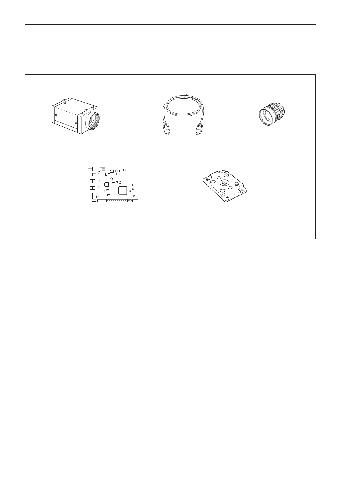
System Components
The XCD-V50CR/V50 Video Camera Module system
comprises the following components.
Overview
Video Camera Module XCD-V50CR/V50
Host Adapter Card
(Commercially available)
IEEE1394b Cable
(9 pin-9 pin 4.5 m)
Tripod Adapter
VCT-ST70I (Isolated type)
C-mount Lens
XCD-V50CR
XCD-V50
4
Page 5
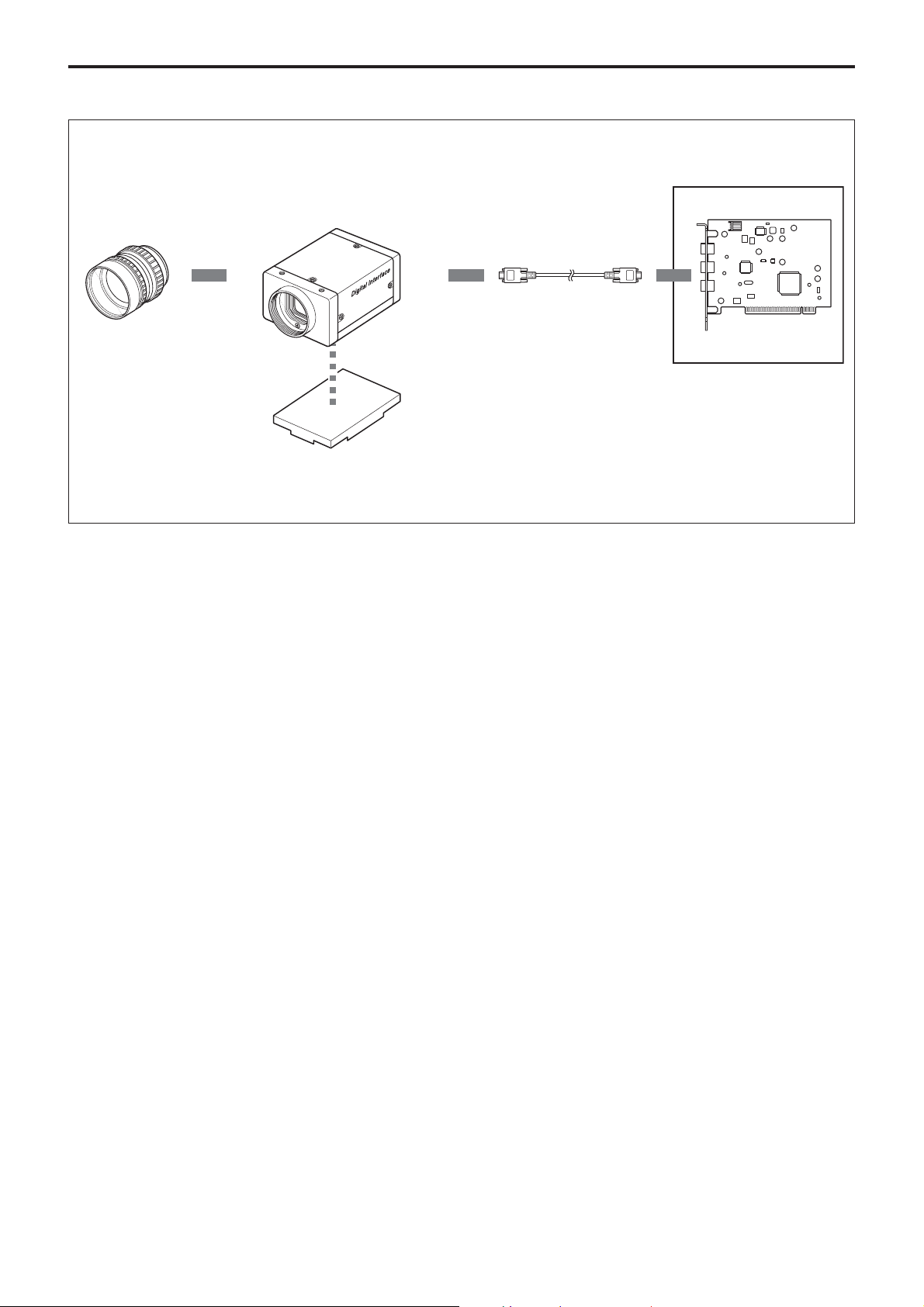
Connection Diagram
Overview
C-mount Lens
XCD-V50CR/V50
IEEE1394b Cable
Host Adapter Card
Host Equipment (PC, etc.)
Tripod Adapter
VCT-ST70I
XCD-V50CR
XCD-V50
5
Page 6
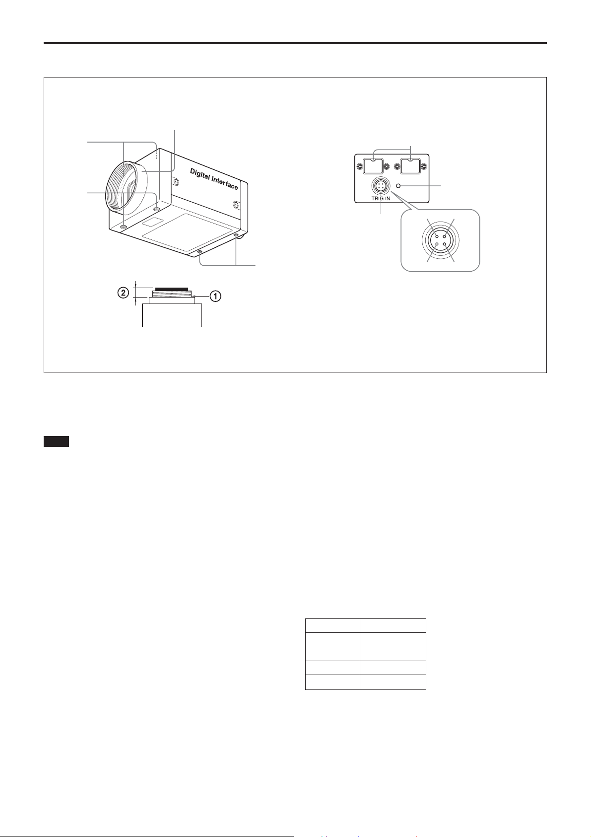
Location of Parts and Operation
Rear PanelFront/Top/Bottom
1
2
Overview
4
3
3
1 Lens mount (C-mount)
Attach any C-mount lens or other optical equipment.
Note
The lens must not project more than 7 mm (9/32 inch)
from the lens mount.
1 Lens mount face 2 7 mm (9/32 inch) or less
2 Auxiliary holes (Top)
3 Reference holes (Bottom)
These precision screw holes are for locking the camera
module. Locking the camera module into these holes
secures the optical axis alignment.
Four screw reference holes of 3 can be used as the
tripod adapor screw holes, too. Screw the tripod
adaptor VCT-ST70I into the four screw holes when
you use a tripod.
5
6
4
3
4 IEEE1394b connectors
Connect the IEEE1394b cable (supplied) to this
connector.
5 Pilot lamp
This lamp indicates the camera module operation
states:
OFF: Camera power OFF
Green: Camera power ON/Video signal output OFF
Orange: Camera power ON/Video signal output ON
6 TRIG IN (Trigger)/Exposure OUT connector
Connect the trigger signal generator (trigger output
connector) to this connector.
When the external trigger function is set to OFF, a
signal indicating the exposure time is output.
Pin No. Signal
1 EXPO-OUT
2 TRG-GND
3TRG-IN
4NC
1
2
XCD-V50CR
XCD-V50
6
Page 7

Functions
Functions
Gain
Manual Gain setting is available with this camera.
The variable range extends from 0 to 18 dB, and the
unit is designed so that the gain can be subdivided and
set to any of 512 steps.
At the factory default setting, the gain is set to 0 dB.
Shutter
This camera allows Manual Shutter setting.
The relationship between the parameter and the
exposure time is given by the following formulas.
Where
P = Parameter (001h ~ C7ch)
E = Exposure time (µs)
E = (Int (P × 0.64) × 32.55) + 10 [µs]
Setting examples
Trigger Shutter
Trigger shutter is useful for capturing images in
response to a trigger that starts the exposure to match a
preset timing. It can also be used to capture an image
using multiple cameras with the same timing. When a
trigger shutter is used, the required trigger is input via
the 4 pin connector on the rear panel. The input signal
is a 5-volt negative pulse. The falling edge of the
signal is detected as the trigger, and the unit is
equipped with an exposure time consisting of the
shutter parameter set as trigger mode 0, and trigger
mode 1 that controls the exposure timing using the
width of the trigger signal pulse. When trigger mode 0
is used, the minimum width of the trigger is 10
microseconds. When trigger mode 1 is used, there is
no limit to the exposure time.
This unit can also be used with a software trigger that
issues the trigger signal via a software command. Both
trigger mode 0 and trigger mode 1 can be used with
software triggers.
XCD-V50CR
XCD-V50
1 (001h) : 10
48 (030h) : 0.99 ms
480 (1E0h) : 10 ms
µ
s
Trigger shutter
4.0 – 5.0 Vp-p
10 µsec or more
Input impedance: 10 kΩ
7
Page 8

Functions
16-bit Mode
The camera supports 16-bit Black & white
(Monochrome) mode, but because the output of the AD
converter is 14-bit, only the least significant 14 bits of
the 16 bits will handle data. The upper 2 bits will be
filled with zeros.
00dddd | dddddddd
ExposureOut
When trigger is OFF, or software trigger is ON, a
signal that indicates the exposure time is output from
the TRIG IN/Exposure OUT connector of the camera.
+5 V
4.7 kΩ
White Balance
(XCD-V50CR only)
You can adjust the R and B gain with respect to G.
Shoot a white object and adjust the two gains to
standardize the signal levels of R, G, and B.
Hue
(XCD-V50CR only)
You can adjust the G gain. Use this feature when you
cannot obtain the correct white balance using the R and
B gain.
The following Bayer patterns are available.
G B
RG
exposure
time
The LOW period that is given by an output wave form
is an approximate guideline. It does not correspond
exactly to the actual exposure time.
XCD-V50CR
XCD-V50
8
Page 9

Camera Command Status Register
This camera complies with IIDC 1394-based Digital
Camera Specification, Version 1.31 (hereinafter
referred to as IIDC v1.31).
The standards document can be purchased from
1394TA (the 1394 Trade Association). Because it is
very helpful in understanding the explanations in this
Technical Manual, we recommend that you purchase a
copy of IIDC v1.31.
Memory Map
1394 devices have a 64-bit address space. The upper
10 bits show the bus ID (0~1023), and the next six bits
show the node ID (0~63). The IIDC standards require
the next 20 bits to be 1.
Control
Control
The remaining 28 bits can be allocated to the camera
as addresses, but in reality, the first 2 bits are fixed at
0, so the largest number of bits that can be allocated to
the camera as address space is 24 bits. The bus and
node IDs may be changed if the topology is restructured because of bus reset, so only the least
significant 32 address bits are shown in this User’s
Guide.
Address Register
F0000000 Base address
F0000400 ConfigROM area
F0F00000 Base addresses for camera commands
F0F00000 CameraInitialize
F0F00100 Video Format Inq
F0F00180 Video Mode Inq
F0F00200 Frame Rate Inq
F0F00400 Basic Func Inq
F0F00500 Feature Element Inq
F0F00600 Isochronous Control register
F0F00800 FeatureControl
Address used by the camera
---BusID--- --------(Must be 1)--------
bbbbbbbb | bbnnnnnn | 11111111 | 11111111 | 11110000 | 11110000 | 00000000 | 00000000
XCD-V50CR
XCD-V50
NodeID
----(
)----
9
Page 10

ConfigROM
Offset 0-7 8-15 16-23 24-31
Bus 400h 04 21 ROM CRC
Info 404h 31 33 39 34
Block 408h 20 FF 60 00
40ch 08 00 46 02 NodeVendorID/ChipID-Hi
410h 00 10 00 01 ChipID-Lo
Root 414h 0003 CRC
Directory 418h 03 08 00 46 ModuleVendorID
41ch 0C 00 83 C0
420h D1 00 00 01 UnitDirectoryOffset
Control
With the exception of bits 8 to 15 of the 400h offset
address field, the length of the entire ConfigROM is
The UnitDirectory offset address is required to be
420h +000004h * 1 = 424h
made up of 21h Quadlets. So the ConfigROM from
400h to 487h is 136 bytes.
Offset 0-7 8-15 16-23 24-31
Unit 424h 0003 CRC
Directory 428h 12 00 A0 2D UnitSpecID
42Ch 13 00 01 02 UnitSoftwareVersion
430h D4 00 00 01 UnitDependentDirectory Offset
For offset address 424h, the length of the
UnitDirectory is 3 Quadlets. UnitSpecID (00A02Dh)
conforms to 1394TA standards. UnitSoftwareVersion
The offset address of UnitDependentInfo is required to
be
430h + 000001h * 4 = 434h
(000102h) conforms to IIDC Standards, Version 1.3X.
XCD-V50CR
XCD-V50
10
Page 11

Offset 0-7 8-15 16-23 24-31
Unit 434h 000B CRC
Dependent 438h 40 3C 00 00 CommandRegsBase
Info 43Ch 81 00 00 0A VendorNameLeaf
440h 82 00 00 0D ModelNameLeaf
444h 38 00 00 10 Unit sub sw version
448h 39 00 00 00 Reserved
44Ch 3A 00 00 00 Reserved
450h 3B 00 00 00 Reserved
454h 3C 00 00 01 Vendor unique info 0
458h 3D 00 00 00 Vendor unique info 1
45Ch 3E 00 00 00 Vendor unique info 2
460h 3F 00 00 00 Vendor unique info 3
Control
For offset address 434h, the length of the
UnitDependentInfo is 11 Quadlets.
The offset address of VendorNameLeaf is required to
be
43Ch + 000002Ah * 4 = 464h
CommandRegsBase is the base address of the camera
control register.
F0000000h + 3c0000h * 4 = F0F00000h
The offset address of ModelNameLeaf is required to
be
440h + 000005Dh * 4 = 474h
Unit sub sw version indicates that this camera
conforms to IIDC Version 1.31.
VendorNameLeaf
Offset 0-7 8-15 16-23 24-31
Vendor 464h 0003 CRC
Name 468h 00 00 00 00
Leaf 46ch 00 00 00 00
470h 53 4F 4E 59 “SONY”
For offset address 464h, the length of the
VendorNameLeaf is 3 Quadlets. The subsequent 8
bytes are fixed at 00. After that, the four characters for
“SONY” are entered.
ModelNameLeaf
Offset 0-7 8-15 16-23 24-31
Model 474h 0004 CRC
Name 478h 00 00 00 00
Leaf 47ch 00 00 00 00
480h 58 43 44 2D “XCD-”
484h 56 35 30 00 “V50”
For offset address 474h, the length of the
ModelNameLeaf is 4 Quadlets. The subsequent 8 bytes
are fixed at 00.
For the XCD-V50, the 7 characters “XCD-V50” come
next. For the XCD-V50CR, the 9 characters “XCDV50CR” come next.
XCD-V50CR
XCD-V50
11
Page 12

Control Base Address
Every register address is decided based on the base
address found in the CommandRegsBase field of
ConfigROM. F0F00000h is the control base address
on this camera.
Inquiring Supported Video Modes
First, we will find out what video formats are
supported.
Address Data
F0F00100h 80000000h
Control
We find that Format0 is supported.
Next, for each format, we will find out which video
modes are supported.
Format0
Address Data
F0F00180h 06000000h
We find video modes 5 and 6 of Format0 are supported.
Next, for each video mode, we will find out which
frame rates are supported.
Address Data
F0F00214h 1C000000h
(Format0Mode5)
F0F00218h 18000000h
(Format0Mode6)
Based on the data above, the formats, modes, and
frame rates supported are shown in the tables below.
Video modes supported
FrameRate PacketSize (bytes)
Format Mode ImageSize ColorCoding 60 30 15 7.5 3.75
05640 × 480 Mono8 aaa ××
2560 1280 640
6 640 × 480 Mono16 × aa ××
2560 1280
XCD-V50CR
XCD-V50
12
Page 13

Control
Video Mode Settings
Select the video mode you want to use from the tables,
and make the required settings. As example, the
register setting for Format0, Mode5, and a frame rate
of 60 fps is shown.
In addition, an isochronous transfer speed of
800 Mbps, and isochronous channel 0 are used in this
example. When you use the camera via the 1394a
interface, set the isochronous transfer speed to 400
Mbps.
When multiple cameras are used simultaneously, set
different isochronous channels for each one.
Address
F0F00600h A0000000h 60fps
(FrameRate)
F0F00604h A0000000h Mode5
(VideoMode)
F0F00608h 00000000h Format0
(VideoFormat)
F0F0060Ch 00008003h Ch=0/800Mbps
(IsoChannel/
IsoSpeed)
Data
Starting/Stopping Video Transfer (ContinuousShot)
In the device driver, after the preparations for
receiving isochronous data are made, video transfer
starts when the following commands are issued.
Address Data
F0F00614h 80000000h
When the following command is issued, video transfer
stops.
Address Data
F0F00614h 00000000h
When the transfer speed is set to 400 Mbps, also make
the following settings.
Address
F0F0060Ch 02000000h Ch=0/400Mbps
(IsoChannel/
IsoSpeed)
Data
Inquiring the Effective Bit Length
You can verify the effective bit length in each mode
after you set the video modes.
Address
F0F00630h 08000000h Mono8 at setting
(FrameRate)
F0F00630h 0E000000h Mono16 at setting
(VideoMode)
Data
XCD-V50CR
XCD-V50
13
Page 14

Control
Feature Controls
This camera supports the following features.
Shutter Controls the exposure time. Can be controlled by both relative control values from 1/100000 of a second to 1/15s, allocated
from 1 to 3196.
Gain Can be changed to 0 to 18 dB, subdivided in 512 steps.
Trigger Sets external trigger mode. Trigger Mode 0 and 1 are available. Software Trigger Mode in which triggers can be output by
software.
The XCD-V50CR supports the following additional features.
White Balance Adjusts the White Balance by adjusting the R and B gain with respect to G.
Hue Adjusts G gain. Use this feature when you cannot obtain the correct White Balance using the R and B gain.
Before sending a command, check the predetermined variable range and check whether the feature supports
AUTO mode.
Address Data Bit*
F0F0050Ch 8900003Fh 0 This feature exists.
(White Balance) 4 The value can be read out.
(XCD-V50CR only) 7 Manual setting can be selected.
8-19 Min. 0
20-31 Max. 63
F0F00510h 8900003Fh 0 This feature exists.
(Hue) 4 The value can be read out.
(XCD-V50CR only) 7 Manual setting can be selected.
8-19 Min. 0
20-31 Max. 63
F0F0051Ch 89001C7Ch 0 This feature exists.
(Shutter) 4 The value can be read out.
7 Manual setting can be selected.
8-19 Min. 1
20-31 Max. 3196
F0F00520h 89000200h 0 This feature exists.
(Gain) 4 The value can be read out.
7 Manual setting can be selected.
8-19 Min. 0 (XCD-V50) or 256 (XCD-V50CR)
20-31 Max. 256 (XCD-V50) or 768 (XCD-V50CR)
F0F00530h 8C81C000h 0 This feature exists.
(Trigger) 4 The value can be read out.
5Feature can be switched between ON and OFF.
8Trigger Source0 exists.
15 Software Trigger Mode exists.
16 Trigger Mode0 exists.
17 Trigger Mode1 exists.
* According to the IEEE1394 specifications, the most significant bit is shown as 0.
Actual control can be carried out by setting registers from F0F00800 onward.
ddd indicates the control value expressed as a 12 bit hexadecimal number.
xxx indicates that any setting made will be ignored.
XCD-V50CR
XCD-V50
14
Page 15

Control
Shutter (exposure time) control
Address Data
F0F0081C 82000ddd Sets Shutter manually.
Gain control
Address Data
F0F00820 82000ddd Sets Gain manually.
Trigger control
Address Data
F0F00830 82000000 Sets to Hardware Trigger Mode0.
82010000 Sets to Hardware Trigger Mode1.
82E00000 Sets to Software Trigger Mode0.
82E10000 Sets to Software Trigger Mode1.
F0F0062C 80000000 Outputs a software trigger.
In Trigger Mode0, automatically reset
to “0” when exposure ends.
00000000 In Trigger Mode1, ends exposure if
“0” is set.
White Balance control (XCD-V50CR only)
Address Data
F0F0080C 82bbbrrr Sets R and B Gain.
“bbb” sets B Gain, “rrr” sets R Gain.
Hue (G Gain) control (XCD-V50CR only)
Address Data
F0F00810 82000ddd Sets G Gain.
XCD-V50CR
XCD-V50
15
Page 16

Notes on the Camera Operations
When using Trigger mode
When this camera is set to accept a trigger at the
fastest possible timing, it can accept overlap of the
next trigger signal in the midst of video transmission.
For this reason, a trigger inhibition period is not
available. Thus, if a trigger signal is input before the
CCD can change to the state where it can accept
exposures, multiple exposures can occur, and it cannot
capture the correct image. Make sure that the
following conditions are met when the trigger is
activated.
Appendix
Appendix
T T
Mode 0: timing after the exposure set by the parameter
is finished
Mode 1: at the trailing edge of the trigger pulse
T≥1/30 sec
XCD-V50CR
XCD-V50
16
Page 17

Specifications
Appendix
Image sensor
Number of effective pixels
Unit cell size 7.4
Interface format IEEE1394b-2002
Transfer speed 800, 400 Mbps
Protocol IIDC 1394-based Digital
Image format 640 × 480 Mono8/16
Frame rate 15/30/60 fps (mono8)
Lens mount C-mount
Flange back 17.526 mm
Minimum illumination
Gamma
Shutter 1/10000 to 1/15 s (at 15 fps)
Gain 0 to 18 dB
External trigger shutter
Power supply/Power consumption
Power consumption 2 W (12 V)
Operating temperature
Storage temperature –20 to +60˚C
Operating relative humidity
Storage relative humidity
Vibration resistance 10 G (20 to 200 Hz, 20 minutes
MTBF 53982 Hrs (Approx. 6.2 years)
Shock resistance 70 G
Dimensions 44 (W) × 29 (H) × 57.5 (D) mm
Mass 120 g
Accessories IEEE1394b cable (1)
1
/3-type progressive scan IT
transfer CCD
Approx. 330,000
659 (H) × 494 (V)
µ
m (H) × 7.4 µm (V)
Camera Specification Version
1.31 Compliant
15/30 fps (mono16)
XCD-V50CR:
20 lx (F0.95, Gain: +18 dB)
XCD-V50:
4 lx (F0.95, Gain: +18 dB)
γ
= 1 (Fixed)
1/10000 to 1/30 s (at 30 fps)
1/10000 to 1/60 s (at 60 fps)
Available (Trigger Mode0/1)
+8 to +30 V (from IEEE1394b
cable)
–5 to +45˚C
20 to 80% (No condensation)
20 to 95% (No condensation)
for each direction-X, Y, Z)
Lens mount cap (1)
4-pin connector for the trigger
input (1)
Operating Instructions (1)
XCD-V50CR
XCD-V50
17
Page 18

CCD Pixel Location (Top View)
Total number of pixels: 692 (H) × 504 (V)
Number of effective pixels: 659 (H) × 494 (V)
Number of output pixels: 640 (H) × 480 (V)
Appendix
XCD-V50CR
XCD-V50
18
Page 19

g
g
Spectral Sensitivity (Relative Response) Parameters
(Without lens and light source parameters.)
XCD-V50
1.0
0.9
0.8
0.7
0.6
0.5
0.4
Relative Response
0.3
Appendix
XCD-V50CR
0.2
0.1
0
400 600 800 1000500 700 900
th [nm]
G
R
1.0
0.9
0.8
0.7
0.6
0.5
0.4
Relative Response
0.3
Wave Len
B
XCD-V50CR
XCD-V50
0.2
0.1
0
400 500 600 700450 550 650
Wave Len
th [nm]
19
Page 20

Dimensions
Appendix
Unit: mm
XCD-V50CR
XCD-V50
20
 Loading...