

Page 1

2004 Sony Corporation
CCD Black-and-White
Video Camera Module
A-C4B-100-11 (1)
Technical Manual
XC-56BB
Page 2

2
XC-56BB
Table of Contents
Overview
Features ..................................................................... 3
System Components ................................................. 4
Connection Diagram ................................................. 4
Location and Function of Parts and Controls ........ 5
Front/Top/Bottom ........................................................ 5
Rear Panel ................................................................. 6
Mode Settings
Input/Output Specifications ..................................... 8
External HD/VD Input Phase Specifications .............. 8
HD/VD Output Specifications ..................................... 9
VD Input Specifications .............................................. 9
HD Input Specifications .............................................. 9
Trigger Pulse Specifications ....................................... 9
Video Output Modes ............................................... 10
Binning OFF ............................................................. 10
Binning ON ............................................................... 10
About the Electronic Shutter .................................. 11
DIP Switches on the Rear Panel .............................. 11
Normal Shutter ......................................................... 11
External Trigger Shutter............................................ 12
Restart/Reset ........................................................... 13
To Set Restart/Reset Mode ...................................... 13
To Use High-rate Scan Mode (A) ............................. 14
External Trigger Shutter .......................................... 16
To Set the External Trigger Shutter .......................... 17
To Use High-rate Scan Mode (B) ............................. 18
Timing Chart ............................................................. 20
Specifications
Main Specifications ................................................. 28
Spectral Sensitivity Characteristics
(Typical Values) ..................................................... 29
CCD Output Waveform Timing Chart ..................... 30
Dimensions .............................................................. 32
Appendix
Available Accessory Lenses .................................. 33
Page 3

3
Overview
XC-56BB
Overview
The XC-56BB is a black-and-white video camera
module using a CCD (Charge Coupled Device) image
sensor.
Features
High image quality
The 330,000-pixel VGA-compatible 1/3 type CCD
image sensor delivers detailed images with the
equivalent of VGA resolution (647 × 493 pixels). The
CCD has square pixels, eliminating the need for aspect
ratio conversion.
Various mode settings
Rear panel switches allow the following mode settings.
• Gain: Fixed/Manual
• Read mode: Normal (30 fps)/Binning (60 fps)
• High-rate scan
• Synchronized input/output
• 75 Ω termination
• Shutter modes: Normal/Trigger shutter
• Shutter speed
External synchronization
The camera module automatically determines whether
to operate in interlace or non-interlace mode from HD
(horizontal drive) and VD (vertical drive) signals input
for external synchronization.
Sync signal output
You can output HD and VD signals from a 12-pin
connector by changing the setting of a rear panel
switch.
Electronic shutter
You can choose from FL (flickerless) mode and a wide
range of image speeds (1/125 to 1/15000 s) for the best
match to shooting conditions.
External trigger shutter function (1/4 to
1/100000 s)
You can obtain a freeze picture by inputting an
external trigger. This function is useful for shooting a
fast-moving object clearly.
High-rate scan
By limiting the number of effective image output lines,
you can obtain image output at high frame rates,
suitable for high-speed image processing.
Binning function
Video signals combining vertically adjacent pixels can
be obtained at 60 fps.
Mounting holes
Mounting screw holes are provided on the reference
plane on the lower surface of the body, allowing
mounting for minimum deviation in the optical axis.
The connector complies with the 12-pin
assignment used by the XC-55BB
The pin assignment is compatible with the existing
model, the XC-55BB.
Page 4
4
Overview
XC-56BB
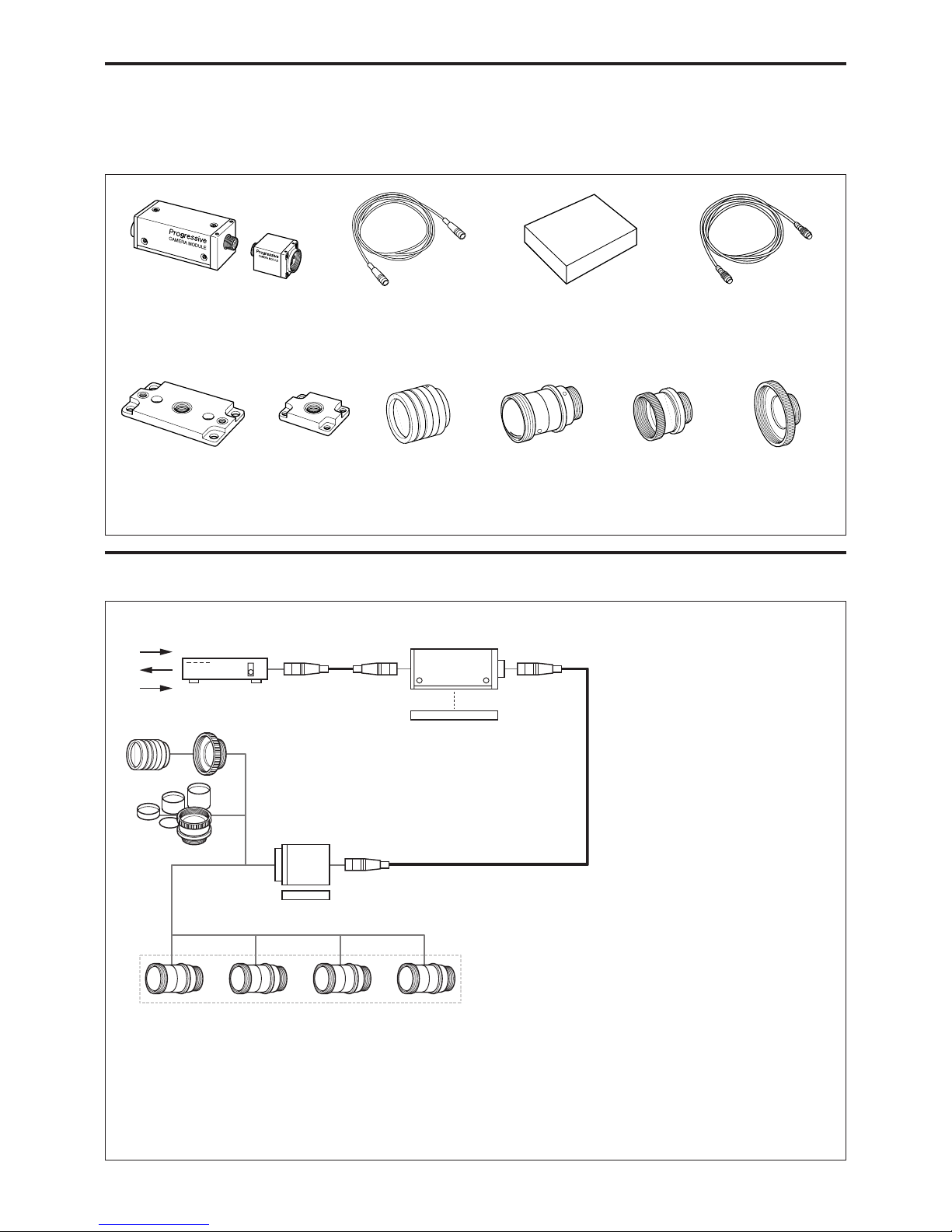
System Components
The XC-56BB Video Camera Module system
comprises the following components.
Connection Diagram
Video camera module
XC-56BB
Camera cables
CCXC-12P02N (2 m)
CCXC-12P05N (5 m)
CCXC-12P10N (10 m)
CCXC-12P25N (25 m)
Camera adaptor
DC-700/700CE
Tripod adaptor
VCT-55I
(for CCU)
C-mount lenses
VCL-50Y-M
VCL-12YM
Close-up ring kit
LO-77ERK
6
7
8
0
qa
9
123
4
5
Special cable for
XC-56BB
Tripod adaptor
VCT-333I
(for CHU)
NF-mount lenses
VCL-03S12XM
VCL-06S12XM
VCL-12S12XM
VCL-12SXM
C-mount adaptor
LO-999CMT
1 Camera adaptor (DC-700/700CE)
2 Camera cable (e.g. CCXC-12P05N)
3 XC-56B Camera Control Unit (CCU)
4 VCT-55I (Tripod adaptor)
5 Special cable for XC-56BB
6 XC-56B Camera Head Unit (CHU)
7 VCT-333I (Tripod adaptor)
8 LO-999CMT C-mount adaptor
9 C-mount lens
If you use a C-mount lens, you can attach a VCL-12YM/
VCL-50Y-M lens. Because of the unique characteristics of
the XC-56BB, you cannot install any other type of lens.
0 LO-77ERK Extension ring kit
qa NF-mount lenses
You can attach a VCL-03S12XM/06S12XM/12S12XM/
12SXM lens.
Page 5
5
Overview
XC-56BB
Location and Function of Parts and Controls
Front/Top/Bottom
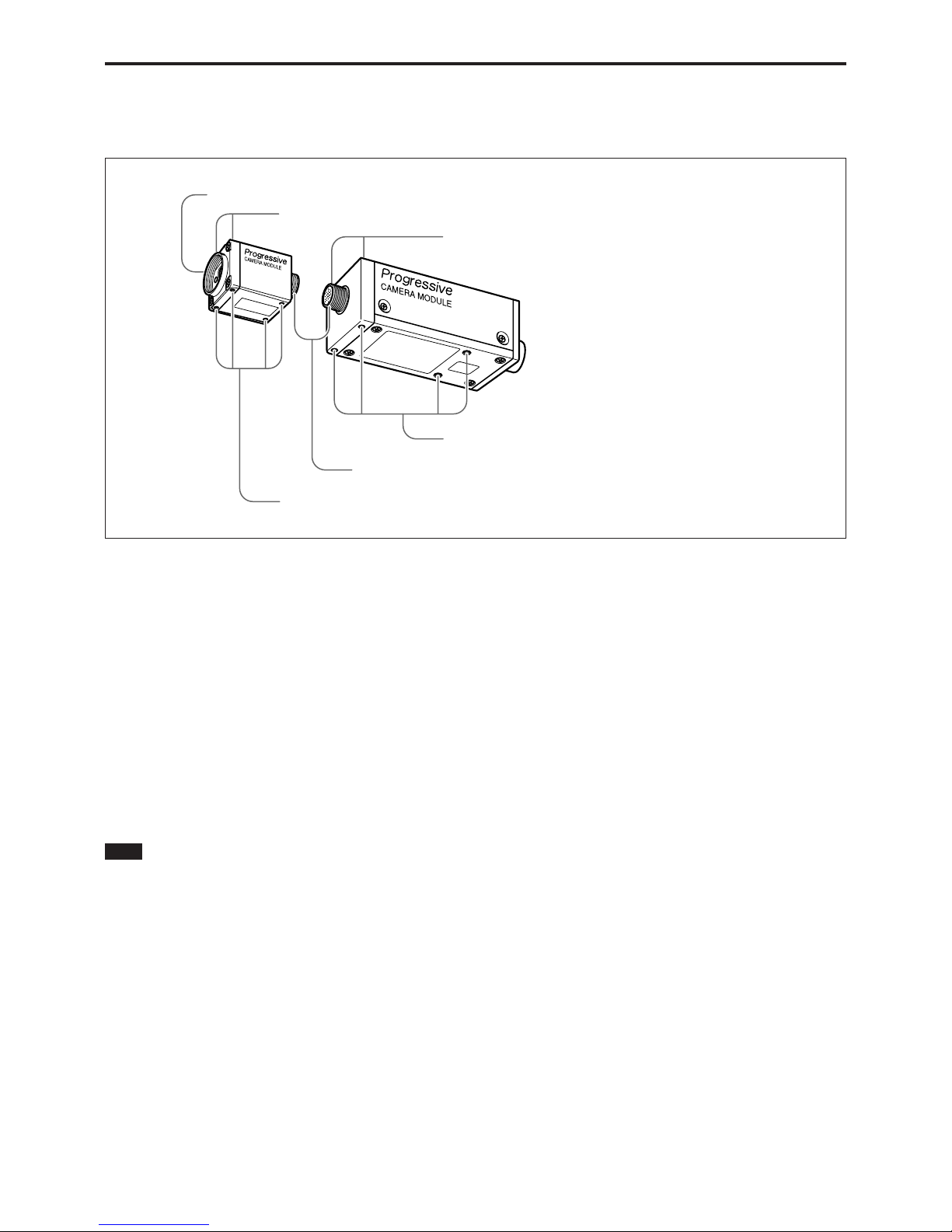
1 Lens mount (NF-mount)
Install an NF mounted lens or optical device, e.g., the
standard lens VCL-12S12XM. If you install a C-mount
lens on the XC-56BB, you will need the C-mount
adaptor LO-999CMT.
2 Reference holes for locking the camera/Tripod
screw holes (head unit)
You can attach a tripod to the reference holes (4) on
the bottom. You will need a tripod adapter VCT-333I
to install the tripod.
There are two more reference holes on the front of the
top surface.
Note
• The XC-56BB head unit (CHU) must have the same
serial number as the control unit (CCU).
• Do not connect or disconnect the supplied cable
while the power is turned on, otherwise the camera
may be damaged.
3 Connector for the special cable
Connect the head unit and the control unit with the
supplied cable.
4 Reference holes for locking the camera/Tripod
screw holes (control unit)
High-precision screw holes for locking the camera
onto the lens mounted surface. Locking the camera
minimizes optical axis deviation.
For details, see the Application Guide.
You can attach a tripod to the reference holes on the
bottom of the head unit. You will need a tripod adapter
VCT-55I to install the tripod.
There are two more reference holes on the front of the
top surface.
1 Lens mount (NF-mount)
2 Reference holes for locking the camera/Tripod screw holes (head unit)
3 Connector for the special cable
4 Reference holes for locking the camera/Tripod screw holes (control unit)
2 Reference holes for locking the camera/Tripod screw holes (head unit)
4 Reference holes for locking the camera/Tripod screw holes (control unit)
Page 6
6
Overview
XC-56BB
Rear Panel
Note
Be sure to turn the power off before making switch
settings.
When flipping/adjusting the switches/knobs (2 to 5),
use screwdrivers that are appropriate for the parts of
the system which you intend to adjust. Otherwise,
malfunctions may occur.
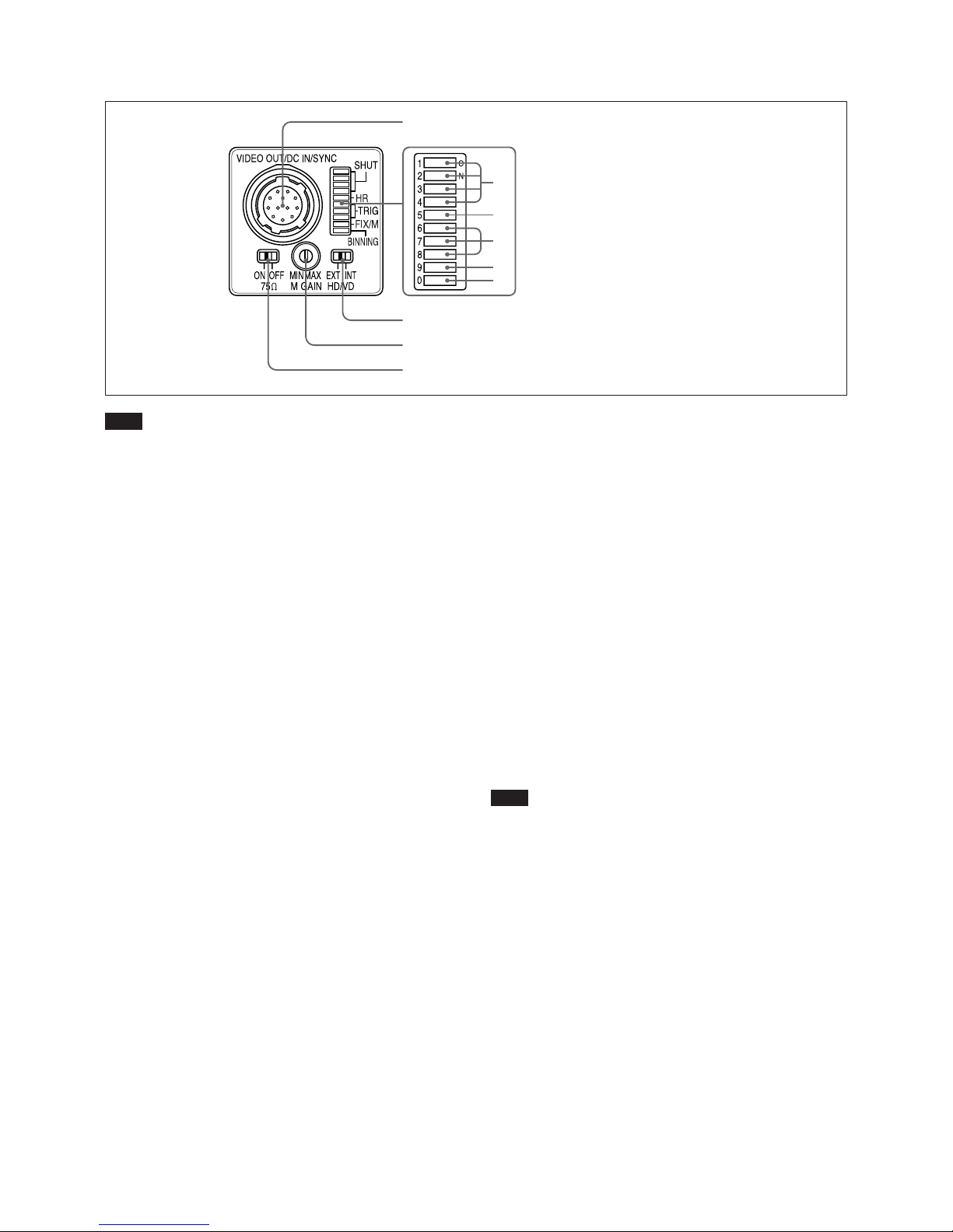
1 VIDEO OUT/DC IN/SYNC (video output/DC
power/sync input signal) connector (12-pin
connector)
Connect a CCXC-12P05N camera cable to this
connector to obtain power from the +12 V DC power
supply and also to enable video signal output from the
camera module. When a sync signal generator is
connected to this connector, the camera module is
synchronized with the external sync signals (HD/VD
signals).
For more information, see “VIDEO OUT/DC IN/SYNC
connector pin assignments” (page 7).
2 Shutter speed/Mode setting DIP switch
1 Shutter speed (bits 1-4)
Set an appropriate shutter speed (factory setting:
OFF).
2 High-rate scan mode switch (bit 5)
The factory setting of this switch is high-rate
scan OFF. If you turn this switch ON to use
high-rate scan mode, you also need to make
pulse rate settings.
For more information, see “To Use High-rate Scan
Mode (A)” (page 14) or “To Use High-rate Scan
Mode (B)” (page 18).
3 Restart reset/External trigger shutter mode
switch (bits 6 to 8)
By inputting an external restart/reset signal, you
can capture the information of single screens at
arbitrary timing. By inputting an external trigger
signal, you can capture fast-moving objects at
precise locations. The factory settings for these
switches are for normal operation.
For more information, see “Restart/Reset” (page 13)
and “External Trigger Shutter” (page 16).
4 Gain switch (bit 9)
This switch selects FIX (fixed) or MANUAL
(manual adjustment) (factory setting: FIX (left
side)).
5 Binning mode switch (bit 0)
Switches the video signal output mode between
binning OFF and binning ON (factory setting:
OFF).
For more information, see “Video Output Modes”
(page 10).
3 HD/VD signal input/output switch
Set the switch to INT to output HD/VD signals from
the camera module.
Set the switch to EXT to input HD/VD signals from an
external unit (factory setting: EXT).
Note
Even when the switch is set to EXT, the camera
module operates in internal synchronization mode
unless an external HD signal is input. In this case,
however, the camera module will not output internal
sync signals.
4 M GAIN (Manual Gain) control knob
If you have selected MANUAL (manual adjustment)
with DIP switch 4, this knob adjusts the gain.
The dimensions of the groove on the knob are 0.5 (W)
× 1.9 (L) × 0.45 (D)mm.
Use a screwdriver that is appropriate for these
dimensions.
The knob can be rotated 260 degrees. Do not rotate the
knob over the stopper on the limit point.
5 75Ω termination switch
Turn this to OFF when not terminating the external
sync signal (factory setting: ON).
1 VIDEO OUT/DC IN/SYNC connector
2 Shutter speed / Mode setting DIP switches
3 HD/VD signal input/output switch
4 M GAIN control knob
5 75Ω termination switch
1
2
3
4
5
Page 7

7
Overview
XC-56BB
VIDEO OUT/DC IN/SYNC connector pin assignments
Pin No. Camera sync output External mode (HD/VD) Restart/Reset External trigger shutter
1 Ground Ground Ground Ground
2 +12 V DC +12 V DC +12 V DC +12 V DC
3 Video output (Ground) Video output (Ground) Video output (Ground) Video output (Ground)
4 Video output (Signal) Video output (Signal) Video output (Signal) Video output (Signal)
5 HD output (Ground) HD input (Ground) HD input (Ground) HD input (Ground)
6 HD output (Signal) HD input (Signal) HD input (Signal) HD input (Signal)
7 VD output (Signal) VD input (Signal) Reset (Signal) VD input (Signal)
8— — — —
9 — — — Trigger pulse input (Signal)
10 — — — —
11 — — — —
12 VD output (Ground) VD input (Ground) Reset (Ground) VD input (Ground)
Rear panel
Factory mode settings of rear panel
Number Switch name Factory mode setting
1 Shutter speed and mode setting DIP switches All bits are OFF (left).
2 75Ω termination switch ON
3 M GAIN control knob —*
4 HD/VD signal input/output switch EXT
* This unit is shipped from the factory with the gain switch (DIP switch 9)
being set to “FIX”, so the M GAIN control knob is not operative unless
the switch setting is changed. When the gain switch (DIP switch 9) is set
to MANUAL, you can rotate this knob to adjust gain over the range 0 to
18 dB.
1
23 4
Model Gain mode Factory setting
Regulation gain setting*
Factory setting of the control knob
(Standard gain setting )
XC-55BB A/F/M F (0 dB) M (This value has been set using the control knob)
T
XC-56BB F/M F (0 dB) F (This value was set by the internal circuitry) MIN ( a little lower than F (0 dB))
* When using many cameras with this setting, if you shoot an object under
a specific light source, the variation of the signal level from each camera
will be minimized.
Gain function comparison chart
Page 8
8
Mode Settings
XC-56BB
External VD
External HD
100 100
1005
Unit: Clock
1 Clk = 81.48 ns
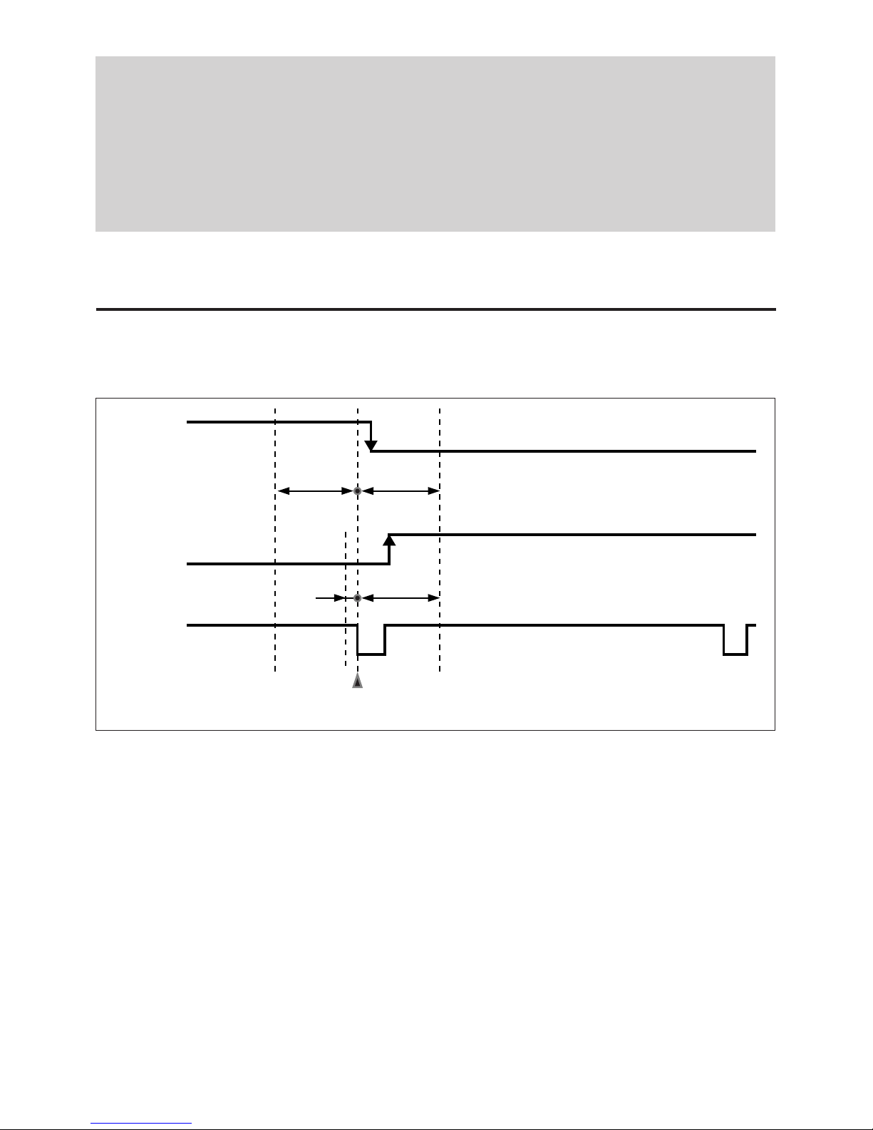
Make sure that the external HD and VD phases against
the standard center phase are as shown in the figure.
External VD falling edge: Input within 100 Clk
before or after the standard center phase.
External VD rising edge: Input within 5 Clk before
or 100 Clk after the standard center phase.
(The rising edge is used only in high-rate scan
mode.)
Note that input outside the specified ranges can lead to
internal reset instability and high-rate interval
instability.
When you restart/reset the camera or operate the
camera by inputting an external trigger shutter pulse,
the V sync signal for the image is output about 1 H
later from the external VD.
Mode Settings
During normal operation: HD phase 63.56 µs, VD
phase 33.37 ms/16.68 ms (binning ON/OFF)
continuous.
Phase timing is as shown above (falling edge only
applied).
During restart/reset or external trigger shutter
mode operation: HD phase 63.56 µs continuous.
VD (reset) any timing where HD phase is within
range shown above.
Input/Output Specifications
External HD/VD Input Phase Specifications
Standard center phase
Falling edge
Rising edge
Page 9
9
Mode Settings
XC-56BB
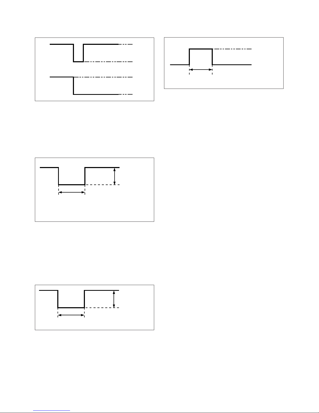
HD/VD Output Specifications
The amplitude level is the typical value when
terminated with 10 kΩ. External HD and VD can be
output when you set the HD/VD signal input/output
switch to INT.
VD Input Specifications
• Input impedance: 75 Ω or 10 kΩ or more.
• Input amplitude 2.0 to 5.0 Vp-p (for both 75 Ω
termination ON and OFF).
• The voltage and pulse width used are as measured at
pin 7 of the 12-pin multi-connector on the rear panel.
HD Input Specifications
• Input impedance: 75 Ω or 10 kΩ or more.
• Input amplitude 2.0 to 5.0 Vp-p (for both 75 Ω
termination ON and OFF)
• The voltage and pulse width used are as measured at
pin 6 of the 12-pin multi-connector on the rear panel.
HD
VD 4.5 V
0 V
4.5 V
0 V
Trigger Pulse Specifications
• Input impedance: 10 kΩ or more.
• The voltage and pulse width used are measured at pin
9 of the 12-pin multi-connector on the rear panel.
5 H – 21 H*
2.0 – 5.0 Vp-p
2.0 µs – 5.0 µs
2.0 – 5.0 Vp-p
0 – 0.6 V
2 – 5.0 V
2 µs – 1/4 s
* These VD width values are only effective when high-rate
scan is OFF.
Page 10
10
Mode Settings
XC-56BB
OFF
0
ON
0
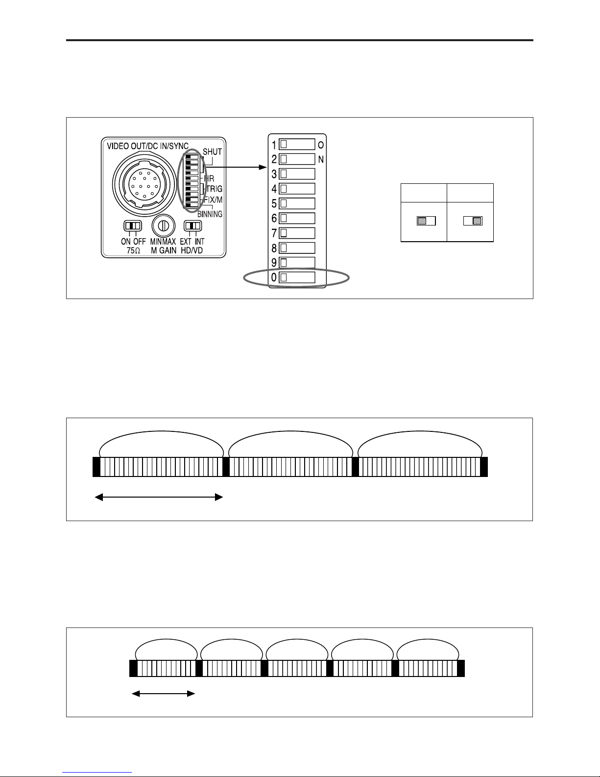
Video Output Modes
This unit has two video signal output modes. Select the
mode with the binning mode switch (DIP switch 0) on
the rear panel.
Binning OFF
Signals for each independent pixel are output from the
VIDEO OUT connector every 1/30 s (line sequential
output).
External synchronization is possible by external HD/
VD.
Binning ON
Mixed signals for vertically adjacent pixels are output
from the VIDEO OUT connector every 1/60 s.
External synchronization is possible by external HD/
VD.
Frame image Frame image Frame image
Binning image Binning image Binning image Binning image Binning image
Rear panel
DIP switches
Binning mode
1/30 s (525 H)
1/60 s (263 H)
Page 11

11
Mode Settings
XC-56BB
About the Electronic Shutter
There are two shutter types: normal shutter and
external trigger shutter. Select them with the DIP
switches on the rear panel.
DIP Switches on the Rear Panel
*1 The electronic shutter cannot be used in restart/reset mode.
*2 High-rate scan can be used in restart/reset mode and in external trigger
shutter mode 1.
Normal Shutter
This mode provides continuous video output with the
electronic shutter selected by switches to capture a
high-speed moving object clearly.
8 8
* “Other modes” refers to restart/reset mode and external trigger shutter
mode.
Rear panel DIP switches
Switches 1 to 4: Shutter speed switches*
1
Switch 5: High-rate scan mode
switch*
2
Switches 6 to 8: Trigger shutter mode
switches
Switch 9: Gain switch (FIX/
MANUAL)
Switch 0: Binning mode switch
(OFF/ON)
Normal
Shutter
Other
modes*
Page 12

12
Mode Settings
XC-56BB
1/125
1
2
3
4
1
2
3
4
1
2
3
4
1
2
3
4
1
2
3
4
1
2
3
4
1
2
3
4
1
2
3
4
1
2
3
4
1/250 1/500 1/1000
1/2000 1/4000 1/8000 1/15000
1/100
Normal shutter speed settings
(Unit: second)
External Trigger Shutter
By inputting an external trigger pulse, the camera is
able to capture fast-moving objects clearly.
For more information, see “External Trigger Shutter” (page
16).
Page 13

13
Mode Settings
XC-56BB
Restart/Reset
To Set Restart/Reset Mode
This mode allows you to capture the information on
single screens at any time by externally inputting
restart/reset signals (HD/VD). To enter this mode, set
the trigger shutter switches (6 to 8) on the rear panel
of the camera as shown in the figure below.
To use restart/reset mode and high-rate scan mode
simultaneously, set the high-rate scan mode switch
(5) to ON (right side).
Long exposure
The Restart/Reset function extends the CCD
accumulation time, resulting in highly sensitive
image capture. This function is effective when you
cannot gain satisfactory sensitivity under normal
operating conditions, or when you want to observe
the trail of a moving object. Extend the VD interval
(T) between external VD pulses.
OFF
5
ON
5
R/R
6
7
8
Rear panel
DIP switches
High-rate scan
EXT-HD
EXT-VD
T
Example of input timing chart
Charge
accumulation
on CCD
VIDEO OUT
Page 14

14
Mode Settings
XC-56BB
To Use High-rate Scan Mode (A)
As shown in the table below, you can increase the
frame rate by setting the high-rate scan mode switch
and the external VD width and frequency. The image
obtained is centered as shown below.
Note
In Restart/Reset mode, video out signals are output
about 1 H later than the external VD.
493 lines
X lines
BLKG interval
Tb [line]
Effective image interval X [line]
External VD interval Tv [line]
External VD
VBLKG
Video out
External VD width
Tw [line]
1 H
Page 15

15
Mode Settings
XC-56BB
Binning OFF mode
Binning ON mode
• The shaded parts of the tables are items that you set or input yourself.
• The number of effective lines (X) with high-rate scan set to ON is
determined by the formula shown below.
Under the condition that Tb = 21 when Tw ≤ 10, and
Tb = Tw + 11 when Tw > 10,
X = Tv – Tb
where Tw: External VD width [line]
Tb: BLKG interval [line]
Tv: VD interval [line]
Note that there is no difference in the number of effective lines between
Binning ON and Binning OFF.
VD interval
Tv [line]
263 (8.36 ms)
175 (5.56 ms)
131 (4.16 ms)
87 (2.76 ms)
External VD width
Tw [line]
High-rate scan OFF
9
13
17
Effective lines
X [line]
240 (15.254 ms)
154 (9.788 ms)
107 (6.801 ms)
59 (3.750 ms)
BLKG interval
Tb [line]
21 (1.335 ms)
21 (1.335 ms)
24 (1.525 ms)
28 (1.780 ms)
Frame rate
[frame/s]
60
90
120
180
* Because the CCD has 493 vertical effective pixels, 11 lines of invalid
pixels are output at the end of the image when high-rate scan is OFF.
(VD interval 525 – effective pixels 493 – BLKG segment 21 = 11 invalid
pixels)
Effective lines
X [line]
493 (31.335 ms)*
239 (15.191 ms)
148 (9.407 ms)
102 (6.483 ms)
BLKG interval
Tb [line]
21 (1.335 ms)
23 (1.462 ms)
27 (1.716 ms)
29 (1.843 ms)
VD interval
Tv [line]
525 (16.7 ms)
262 (8.33 ms)
175 (5.56 ms)
131 (4.16 ms)
Frame rate
[frame/s]
30
60
90
120
External VD width
Tw [line]
High-rate scan OFF
12
16
18
Page 16

16
Mode Settings
XC-56BB
External Trigger Shutter
Inputting an external trigger pulse enables the camera
to capture first-moving objects clearly.
Set DIP switches 6, 7, and 8 on the rear panel to Mode
1 or Mode 2.
OFF
5
ON
5
6
7
8
6
7
8
When you set the trigger pulse width to 1/3 of a second
or more, the output signal changes to the normal
VIDEO signal.
Mode 1
Mode 2
High-rate scanning
Note
High-rate scan mode cannot be used while in external
trigger shutter mode 2.
There are two modes for the timing in which video
signals are obtained.
• Mode 1 (Non-reset mode)
In this mode, a video signal synchronized with a VD
signal is output after a trigger pulse is input.
– The video signal is synchronized with the external
VD signal when an external HD*/VD signal is
input.
– The video signal is synchronized with an internal
VD signal when no external HD*/VD signal is
input.
* External or internal synchronization is selected
automatically depending on the presence or absence
of external HD input.
• Mode 2 (Reset mode)
In this mode, an internal VD is reset, then a video
signal is output a certain period of time after trigger
pulse input.
(High-rate mode is
compatible with Mode 1
only.)
Rear panel
DIP switches
Page 17

17
Mode Settings
XC-56BB
1
2
3
4
Mode 1 (Non-reset mode)
1
2
3
4
Mode 2 (Reset mode)
Using trigger pulse width
Set all DIP switches (1 to 4 on the rear panel) to OFF.
You can obtain an arbitrary shutter speed by setting the
trigger pulse width to the range of 2
µ
sec to
250 msec.
Exposure time = Trigger pulse width + 8 µsec
Note
An incorrect video signal will be output if you input a
new trigger pulse before the video signal output for the
previous trigger pulse is output completely.
To Set the External Trigger Shutter
There are two ways to set the shutter speed.
Using the DIP switches on the rear panel
For shutter speeds, see the following table.
Mode 1 (Non-reset mode)/Mode 2 (Reset mode)
1/125
1
2
3
4
1
2
3
4
1
2
3
4
1
2
3
4
1
2
3
4
1
2
3
4
1
2
3
4
1
2
3
4
1
2
3
4
1
2
3
4
1/250 1/500 1/1000
1/2000 1/4000 1/10000 1/25000
1/50000 1/100000
1
2
3
4
1/100
(Unit: second)
Page 18

18
Mode Settings
XC-56BB
To Use High-rate Scan Mode (B)
In external trigger shutter mode 1, you can increase the
rate by setting the shutter speed to the trigger pulse
width, and setting the high-rate scan mode switch on
the rear panel, the trigger interval, the external VD
phase and the external VD width.
The image is centered as shown below.
Note
In external trigger shutter mode, video out signals are
output about 1 H later than the external VD.
BLKG interval Tb [line]
Effective image interval X [line]
Trigger interval T [line]
X lines
493 lines
External VD
Video out
Trigger
External VD
width Tw [line]
Input of the trigger falling edge terminates the image
output.
Note that input of a trigger pulse is needed in the
effective image interval to control the ending of image
output, and this affects the image at the trigger rising
edge.
1 H
Page 19

19
Mode Settings
XC-56BB
Binning OFF mode
Binning ON mode
• The shaded parts of the tables are items that you set or input yourself.
• The table is an example in external trigger shutter mode 1 where the
trigger pulse width is 100 µs, and the time from the trigger rising edge to
external VD falling edge is about 1 H (63.56 µs). In this case, about 2
lines at the end of the effective image segment are affected by trigger
input.
• The number of effective lines (X) with high-rate scan set to ON is
determined by the formula shown below.
Under the condition that Tb = 21 when Tw ≤ 10, and
Tb = Tw + 11 when Tw > 10,
X = T – Tb – 2
where Tw: External VD width [line]
Tb: BLKG interval [line]
T: Trigger interval [line]
2: Ineffective interval [H] caused by trigger input
Note that there is no difference in the number of effective lines between
Binning ON and Binning OFF.
* Because the CCD has 493 vertical effective pixels, 11 lines of invalid
pixels are output at the end of the image when high-rate scan is OFF.
(VD interval 525 - effective pixels 493 - BLKG segment 21 = 11 invalid
pixels)
Effective lines
X [line]
493 (31.335 ms)*
237 (15.064 ms)
146 (9.280 ms)
100 (6.356 ms)
Trigger interval
T [line]
525 (16.7 ms)
262 (8.33 ms)
175 (5.56 ms)
131 (4.16 ms)
External VD width
Tw [line]
High-rate scan OFF
12
16
18
BLKG interval
Tb [line]
21 (1.335 ms)
23 (1.462 ms)
27 (1.716 ms)
29 (1.843 ms)
Frame rate
[frame/s]
30
60
90
120
Trigger interval
T [line]
263 (8.36 ms)
175 (5.56 ms)
131 (4.16 ms)
External VD width
Tw [line]
High-rate scan OFF
9
13
Effective lines
X [line]
240 (15.254 ms)
152 (9.661 ms)
105 (6.674 ms)
BLKG interval
Tb [line]
21 (1.335 ms)
21 (1.335 ms)
24 (1.525 ms)
Frame rate
[frame/s]
60
90
120
Page 20

20
Mode Settings
XC-56BB
3
3
2
2
1
1
Timing Chart
When set to Mode 1 (Non-reset mode)
Setting the shutter speed using trigger pulse width
◆ HD/VD input
• Continuous VD input
External trigger shutter operation
Normal operation*
3
Mode transition state
External input
inhibition area
(50 ms)
External trigger
shutter operation
Exposure time (Te)*
2
Exposure
time (Te)
*
2
Exposure time (Te)
*
2
Trigger pulse width*
3
T: T=under 10 µs*
4
T: T=under 10 µs*
4
10 µs or more
64 µs
10 µs
Trigger*
1
External HD*
1
External VD*
1
(Continuous
VD)
EXT-VD
Video out
TRG
EXT-VD
EXT-VD
*1 This is an external input signal. Make sure to input
both HD and VD signals.
*2 Exposure time (Te)
Te = Trigger pulse width + 8
µ
sec
(The effective trigger pulse width for the external
trigger shutter operation is between 2
µ
s and 1/4
s.)
*3 Normal operation is resumed when the trigger
pulse width is 1/3 s or more. The trigger falling
edge restores external trigger shutter operation. At
this time, the 50 ms after the falling edge of the
trigger pulse is an external trigger input inhibition
area. There is no guarantee of operation for any
trigger input in this period.
*4 If there is a falling edge on the external VD within
a period of +10
µ
s from the falling trigger edge (1
and 2 in the figure), it is not defined whether the
image is output for the external VD falling edge or
the image is output for the next external VD falling
edge. (1 in the figure shows that the image is
output for the next external VD. 2 shows the
image for the external VD.) In any other case, the
image is output for the external VD falling edge
after the trigger falling edge (3 in the figure).
Note
An image is not output correctly when the next trigger is
input before the image for the previous trigger has been
output.
Page 21

21
Mode Settings
XC-56BB
Setting the shutter speed using trigger pulse width
◆ HD/VD input
• Continuous HD input/Single VD input
*1 This is an external input signal. Make sure to input
both HD and VD signals in this case. Input the
signal so that the VD phase aligns with the HD
falling edge.
*2 Exposure time (Te)
Te = Trigger pulse width + 8
µ
sec
(The effective trigger pulse width for the external
trigger shutter operation is between 2
µ
s and 1/4 s.)
*3 Normal operation is resumed when the trigger
pulse width is 1/3 s or more. The trigger falling
edge restores external trigger shutter operation. At
this time, the 50 ms after the falling edge of the
trigger pulse is an external trigger input inhibition
area. There is no guarantee of operation for any
trigger input in this period.
*4 Input the external VD within the period of 10
µ
s to
75 ms after the trigger falling edge (1 and 2 in
the figure). There is no guarantee of operation for
any other input (the output level of the video signal
will vary, and the S/N ratio will be degraded). If an
invalid signal is input, the input is changed to a
valid signal and, after several V signals, normal
operation resumes.
Note
Make sure that the trigger signal and the VD signal
make up a pair.
An image is not output correctly when the next trigger
is input before the image for the previous trigger has
been output.
External trigger shutter operation
Normal operation*
3
Mode transition state
External input
inhibition area
(50 ms)
External trigger
shutter operation
Exposure time (Te)*
2
Exposure time
(Te)*
2
Trigger pulse width*
3
T: T=10 µs to 75 ms*
4
Min. 10 µs
Trigger*
1
External HD*
1
External VD*
1
(Single VD)
Video out
1
1
2
2
Page 22

22
Mode Settings
XC-56BB
Setting the shutter speed using trigger pulse width
◆ No HD/VD input (Internal synchronization)
*1 This is an external input signal.
*2 Exposure time (Te)
Te = Trigger pulse width + 8
µ
s
(The effective trigger pulse width for the external
trigger shutter operation is between 2
µ
s and 1/4 s.)
*3 Normal operation is resumed when the trigger
pulse width is 1/3 s or more. The trigger falling
edge restores external trigger shutter operation. At
this time, the 50 ms after the falling edge of the
trigger pulse is an external trigger input inhibition
area. There is no guarantee of operation for any
trigger input in this period.
*4 The internal VD signals are output as long as there is
no external input and the HD/VD signal input/output
switch on the rear panel is set to INT.
*5 In external trigger operation, the image is output
for the internal VD falling edge after the trigger
falling edge (1 and 2 in the figure). If the period
from the trigger falling edge to the internal VD
falling edge (T in the figure) is under 10
µ
s, it is
not defined whether the image is output for the
internal VD falling edge or the image is output for
the next internal VD falling edge. (3 in the figure
shows that the image is output for the next internal
VD).
Note
An image is not output correctly when the next trigger
is input before the image for the previous trigger has
been output.
External trigger shutter operation
Normal operation*
3
Mode transition state
External input
inhibition area
(50 ms)
External trigger
shutter operation
Exposure
time (Te)*
2
Exposure time
(Te)*
2
Trigger pulse width*
3
T: T=10 µs or more*
5
Trigger*
1
Internal VD*
4
Video out
Exposure
time (Te)*
2
T: T=under 10 µs*
5
1
1
2
2
3
3
Page 23

23
Mode Settings
XC-56BB
Setting the shutter speed using DIP switches
◆ HD/VD input
• Continuous VD input
*1 This is an external input signal. Make sure to input
both HD and VD signals.
*2 The exposure time (Te) is determined by the
setting of DIP switches.
For details, see page 17.
*3 Normal operation is resumed when the trigger
pulse width is 1/3 s or more. The trigger falling
edge restores external trigger shutter operation. At
this time, the 50 ms after the falling edge of the
trigger pulse is an external trigger input inhibition
area. There is no guarantee of operation for any
trigger input in this period.
External trigger shutter operation
Normal
operation*
3
Mode transition state
External input
inhibition area
(50 ms)
External trigger
shutter operation
Exposure time (Te)*
2
Exposure time
(Te)*
2
Trigger pulse width*
3
T: T=under 10 ms*
4
Exposure time (Te)*
2
2 µs to 250 ms
T: T=10 ms or more*
4
T: T=10 ms or
more*
4
Trigger*
1
External HD*
1
Video out
External VD*
1
(Continuous
VD)
*4 An image is output when an external VD signal
falls 10 ms or more after a trigger pulse rises (2
and 3 in the figure). If the period from the trigger
rising edge to the external VD falling edge (T in
the figure) is under 10 ms, it is not defined whether
the image is output for the external VD falling
edge or the image is output for the next external
VD falling edge. (1 in the figure shows that the
image is output for the next external VD).
Note
An image is not output correctly when the next trigger
is input before the image for the previous trigger has
been output.
1
1
3
3
2
2
Page 24

24
Mode Settings
XC-56BB
Setting the shutter speed using DIP switches
◆ HD/VD input
• Continuous HD input/Single VD input
*1 This is an external input signal. Make sure to input
both HD and VD signals in this case. Input the
signal so that the VD phase aligns with the HD
falling edge.
*2 The exposure time (Te) is determined by the
setting of the DIP switches.
For details, see page 17.
*3 Normal operation is resumed when the trigger
pulse width is 1/3 s or more. The trigger falling
edge restores external trigger shutter operation. At
this time, the 50 ms after the falling edge of the
trigger pulse is an external trigger input inhibition
area. There is no guarantee of operation for any
trigger input in this period.
*4 Input the external VD within the period of 10
ms to
85 ms after the trigger rising edge (1 and 2 in
the figure). There is no guarantee of operation for
any other input (the output level of the video signal
will vary, and the S/N ratio will be degraded). If an
invalid signal is input, the input is changed to a
valid signal, and after several V signals, normal
operation resumes.
Note
Make sure that the trigger signal and the VD signal
make up a pair.
An image is not output correctly when the next trigger
is input before the image for the previous trigger has
been output.
External trigger shutter operation Normal operation*
3
Mode transition state
External input
inhibition area
(50 ms)
External trigger
shutter operation
Exposure time (Te)*
2
Exposure time
(Te)*
2
Trigger pulse width*
3
Trigger*
1
External HD*
1
Video out
External VD*
1
(Single VD)
Min.10 ms
2 µs to 250 ms
1
1
2
2
T: T=10 ms to 85 ms*
4
Page 25

25
Mode Settings
XC-56BB
Setting the shutter speed using DIP switches
◆ No HD/VD input (Internal synchronization)
*1 This is an external input signal.
*2 The exposure time (Te) is determined by the
setting of the DIP switches.
For details, see page 17.
*3 Normal operation is resumed when the trigger
pulse width is 1/3 s or more. The trigger falling
edge restores external trigger shutter operation. At
this time, the 50 ms after the falling edge of the
trigger pulse is an external trigger input inhibition
area. There is no guarantee of operation for any
trigger input in this period.
*4 The internal VD signals are output as long as there
is no external input and the HD/VD signal
input/output switch on the rear panel is set to INT.
*5 An image is output when an internal VD signal
falls 10 ms or more after a trigger pulse rises (2
and 3 in the figure). If the period from the
trigger rising edge to the internal VD falling edge
(T in the figure) is under 10 ms, it is not defined
whether the image is output for the internal VD
falling edge or the image is output for the next
internal VD falling edge. (1 in the figure shows
that the image is output for the next internal VD).
Note
An image is not output correctly when the next
trigger is input before the image for the previous
trigger has been output.
External trigger shutter operation
Normal
operation*
3
Mode transition state
External input
inhibition area
(50 ms)
External trigger
shutter operation
Exposure time (Te)*
2
Exposure time
(Te)*
2
Trigger pulse width*
3
T: T=under 10 ms*
5
Trigger*
1
Internal VD*
4
Video out
T: T=10 ms or
more*
5
2 µs to 250 ms
T: T=10 ms or more*
5
Exposure time (Te)*
2
1
1
2
3
3
2
Page 26

26
Mode Settings
XC-56BB
When set to Mode 2 (Reset mode)
Setting the shutter speed using trigger pulse width
*1 This is an external input signal.
*2 Exposure time (Te)
Te = Trigger pulse width + 8
µ
sec
(The effective trigger pulse width for the external
trigger shutter operation is between 2
µ
s and 1/4 s.)
*3 Normal operation is resumed when the trigger
pulse width is 1/3 s or more. The trigger falling
edge restores external trigger shutter operation. At
this time, the 50 ms after the falling edge of the
trigger pulse is an external trigger input inhibition
area. There is no guarantee of operation for any
trigger input in this period.
External trigger shutter operation
Normal operation*
3
Mode transition state
External input
inhibition area
(50 ms)
External trigger
shutter operation
Exposure time (Te)*
2
Exposure time
(Te)*
2
Trigger pulse width*
3
Trigger*
1
Video out
1 H to 2 H*
4
1 H to 2 H*
4
*4 A VD signal is generated after 1 H to 2 H from the
trigger falling edge, then the image is output
synchronized with the VD generation.
Note
An image is not output correctly when the next trigger
is input before the image for the previous trigger has
been output.
Page 27

27
Mode Settings
XC-56BB
Setting the shutter speed using the DIP switches
*1 This is an external input signal.
*2 The exposure time (Te) is determined by the
setting of the DIP switches.
For details, see page 17.
*3 Normal operation is resumed when the trigger
pulse width is 1/3 s or more. The trigger falling
edge restores external trigger shutter operation. At
this time, the 50 ms after the falling edge of the
trigger pulse is an external trigger input inhibition
area. There is no guarantee of operation for any
trigger input in this period.
T*
4
External trigger shutter operation
Normal operation*
3
Mode transition state
External input
inhibition area
(50 ms)
External trigger
shutter operation
Exposure time (Te)*
2
Exposure time
(Te)*
2
Trigger pulse width*
3
Trigger*
1
Video out
T*
4
2 µs to 250 ms
*4 The image is output at the shortest timing from the
trigger rising edge according to the DIP switch
setting.
Note
An image is not output correctly when the next trigger
is input before the image for the previous trigger has
been output.
Page 28

28
Specifications
XC-56BB
Specifications
Main Specifications
Image pickup system
Image pickup device
Progressive scan 1/3 type CCD
Number of effective pixels
659 × 494 (H/V)
Optical black 33 pixels per horizontal scan line
CCD vertical driving frequency
15.735 kHz ±1%
CCD horizontal driving frequency
12.2727 MHz
Cell size 7.4 × 7.4 µm (H/V)
Chip size 5.84 × 4.94 mm (H/V)
Optical and other systems
Lens mount NF-mount
Flange back 12.00 mm
Synchronization system
Internal/External (automatically
switched according to input
signal)
External synchronization input/output
HD/VD (HD/VD level: 2 to 5 Vp-p)
Allowable frequency deviation of external
synchronization
±1% (in horizontal synchronous
frequency)
H Jitter Less than 20 ns
Scan lines 525-line/263-line (Normal mode/
Binning mode)
Scanning system Non-interlace
Video output 1.0 Vp-p, sync negative, 75 Ω,
unbalanced
Output signal frequency
29.97 Hz/59.95 Hz (Normal mode/
Binning mode)
Effective lines 647 × 493 (H/V)
Horizontal resolution
500 TV lines
Sensitivity F8 (400 lx with FIX Gain)
Minimum illumination
0.5 lx (with gain manually adjusted
to maximum, F1.4)
Video S/N ratio 58 dB
Gain Fixed/Manually adjustable
Gamma compensation
1 (fixed)
White clip 820 mV ±70 mV
Read mode Normal mode/Binning mode
Shutter External trigger shutter
Shutter speed External trigger shutter: 1/4 to
1/100000 s
Power requirements
+12 V DC (range: +10.5 to +15 V)
Power consumption
2.2 W
Operating temperature
–5 to +45˚C (23 to 113˚F)
Storage temperature
–30 to +60˚C (–22 to +140˚F)
Operating humidity
20 to 80% (no condensation)
Storage humidity 20 to 95% (no condensation)
Vibration resistance
10 G (20 to 200 Hz)
Shock resistance 70 G
External dimension (w/h/d)
CHU: 22 × 22 × 30 mm
(
7
/8 × 7/8 × 1 3/16 inches)
CCU: 29 × 29 × 67 mm
(1
3
/16 × 1 3/16 × 2 3/4 inches)
Mass CUU: Approx. 40 g (1 oz.)
CHU: Approx. 100 g (4 oz.)
MTBF 73,880 hours (about 8.4 years)
Accessories Lens mount cap (1)
Operating Instructions (1)
Special cable (1)
Ferrit core (1)
Design and specifications are subject to change
without notice.
Page 29

29
Specifications
XC-56BB
0.0
400
500 600
700
800 900 1000
0.1
0.2
0.3
0.4
0.5
0.6
0.7
0.8
0.9
1.0
Wavelength (nm)
Relative
sensitivity
Spectral Sensitivity
Characteristics
(Typical Values)
(Lens characteristics included, and light source
characteristics excluded.)
Page 30

30
Specifications
XC-56BB
CCD Output Waveform Timing Chart
Horizontal Output Waveform Timing Chart
CCD
output signal
Camera video
output signal
(Typical value)
1 horizontal scan period 780
Optical
black
Horizontal
transfer stop
period
Dummy
bits
Optical
black
Effective total pixels 659
Output video period 647Horizontal blanking period 133
Values without units indicate the clock counts.
(63.56 µs)
(6.36 µs)
81.48 ns
HD
(10.84 µs)
(52.72 µs)
HSYNC 58
(1.47 µs)
(4.73 µs)
(4.64 µs)
78
18
57
8
4
31
72
16
2
Page 31

31
Specifications
XC-56BB
125
6
263
347
8
9
1011121314151617181920
21
263
12
34
5
12354
67
8
24567
8
9
1
3
1011
1213
261
262
494
492493
490491
488489
125634789
1011121314151617181920
21
12
34
5
12354
67
8
24567
8
9
1
3
1011
1213
1415
1617
1819
20212222
232324
25
222324
14151617
1819
2021
Vertical Output Waveform Timing Chart (Binning ON)
Camera video
output signal
(Typical value)
* The transfer stop period is included in the dummy bits.
CCD output signal
263 H
9 H
(572 µs)
VD
HD
SG
9 H
(572 µs)
Dummy bits*
Optical
black
Optical
black
Optical
black
Vertical blanking period (21 H)
(1.335 ms)
2345678
493
494
125
6
525
347
8
525 1 2 3 4 5 1
9
1011121314151617181920
1
2
21
514
515
516
517
518
519
520
521
522
523
524
525
2345678
1256347
8
525 1 2 3 4 5 1
9
1011121314151617181920
1
2
21
496496
* The transfer stop period is included in the dummy bits.
CCD output signal
Camera video
output signal
(Typical value)
Dummy bits*
Vertical blanking period (21 H)
525 H
9 H
(572
µ
s)
(1.335 ms)
VD
HD
SG
9 H
(572 µs)
Optical black
Optical black
Dummy bits*
Optical black
Vertical blanking period (21 H)
(1.335 ms)
Dummy bits*
Vertical blanking period (21 H)
(1.335 ms)
Video
output
Video
output
Vertical Output Waveform Timing Chart (Binning OFF)
Page 32

32
Specifications
XC-56BB
Dimensions
Unit: mm (inches)
4-M3 depth 4 (3/16)
Progressive
CAMERA MODULE
NO.
2.3 (3/32)
ø19
12 (
1
/2)
22 (
7
/8)
22 (
7
/8)
22 (7/8)5 (7/32)
4.5 (
3
/16)
30 (1
3
/16)
(
3
/4)
Progressive
CAMERA MODULE
SEE
INSTRUDUCTION
MANUAL
VIDEO OUT/DC IN/SYNC
SHUT
HR
FIX/M
TRIG
BINNING
ON OFF
75Ω
HD/VDM GAIN
EXT INTMIN MAX
29 (1 3/16)
5.8 (
1
/4)
3.5 (
5
/32)
20 (
13
/16)
44.5 (1
13
/16)
67 (2
3
/4)
80.8 (3
1
/4)
8 (
11
/32)
29
(1
3
/16)
4-M2 depth 2.5 (1/8)
Page 33

33
Appendix
XC-56BB
Available Accessory Lenses
The following shows the specifications of the available accessory lenses.
List of NF-Mount Lens
Model name
Focal distance (mm) (inches)
Operation
Field angle
(Horizontal × Vertical)
MOD* (mm) (inches)
Image pickup range during
maximum proximity
(Horizontal × Vertical)
(mm) (inches)
Back focus
Flange back
Weight
Iris
1/3 type CCD
Maximum aperture ratio
Focus
VCL-03S12XM
3.5 (5/32)
1:1.8
Manual
Manual
79.3° × 59.3°
300 (11 7/8)
609 × 457
(24 × 18)
9.57 mm
(3/8 inches)
12 mm
(1/2 inches)
40 g (1 oz)
VCL-06S12XM
6 (1/4)
1:1.4
44.1° × 33.3°
259 × 189
(10 1/4 × 7 1/2)
12 mm
(1/2 inches)
25 g (1 oz)
300 (11 7/8)
8.57 mm
(11/32 inches)
VCL-12S12XM
12 (1/2)
1:1.4
22.4° × 16.8°
300 (11 7/8)
103 × 77
(4 1/8 × 3 1/8)
11.62 mm
(15/32 inches)
12 mm
(1/2 inches)
25 g (1 oz)
VCL-12SXM
12 (1/2)
1:1.4
22.59° × 17.14°
100 (4)
47 × 35
(1 7/8 × 1 7/16)
8.55 mm
(11/32 inches)
12 mm
(1/2 inches)
26 g (1 oz)
Appendix
Model name
Focal distance (mm) (inches)
Operation
Field angle
(Horizontal × Vertical)
MOD* (mm) (inches)
Image pickup range during
maximum proximity
(Horizontal × Vertical)
(mm) (inches)
Back focus
Flange back
Weight
Iris
1/3 type CCD
Maximum aperture ratio
Focus
Manual
Manual
VCL-12YM
12 (1/2)
1:1.8
22.4° × 16.9°
120 × 90
(4 3/4 × 3 5/8)
17.526 mm
(23/32 inches)
40 g (1 oz)
300(11 7/8)
10.99 mm
(7/16 inches)
VCL-50Y-M
50 (2)
1:2.8
5.5° × 4.1°
500 (19 3/4)
48 × 36
(1 15/16 × 1 7/16)
22.10 mm
(7/8 inches)
17.526 mm
(23/32 inches)
50 g (2 oz)
None
List of C-Mount Lens (when you use the LO-999CMT C-mount adaptor)
* MOD: Minimum Object Distance between the
tip of the lens body and the object.
Sony reserves the right to change
specifications of the products and
discontinue products without notice.
Technical information contained herein is
for reference only and does not convey any
license by any implication or otherwise
under any intellectual property right or
other right of Sony or third parties.
Sony cannot assume responsibility for any
right infringements arising out of the use of
this information.
 Loading...