

Page 1
2-693-883-02(1)
UHF Synthesized
Transmitter
DRAFT version
Operating Instructions
U3032/U4244
WRT-8P
©2006 Sony Corporation
Page 2

English
Owner’s Record
The model number plate is located on the
side and the serial number is located inside
the battery compartment. Record the model
and serial numbers in the space provided
below. Refer to these numbers whenever
you call upon your Sony dealer regarding
this product.
M od e l N o .
Notice for customers in the
U.S.A.
Use of Sony wireless devices is regulated
by the Federal Communications
Commission as described in Part 74 subpart
H of the FCC regulations and users
authorized thereby are required to obtain an
appropriate license.
You are cautioned that any changes or
modifications not expressly approved in
this manual could void your authority to
operate this equipment.
IMPORTANT NOTE: To comply with
the FCC RF exposure compliance
requirements, no change to the antenna or
the device is permitted. Any change to the
antenna or the device could result in the
device exceeding the RF exposure
requirements and void user's authority to
operate this device.
This equipment complies with FCC
radiation exposure limits set forth for an
uncontrolled environment.
FCC Radiation Exposure Statement:
The available scientific evidence does not
show that any health problems are
associated with using low power wireless
devices. There is no proof, however, that
these low power wireless devices are
absolutely safe. Low power Wireless
devices emit low levels of radio frequency
S er i al N o .
energy (RF) in the microwave range while
being used. Whereas high levels of RF can
produce health effects (by heating tissue),
exposure to low level RF that does not
produce heating effects causes no known
adverse health effects. Many studies of low
level RF exposures have not found any
biological effects. Some studies have
suggested that some biological effects
might occur, but such findings have not
been confirmed by additional research.
Notice for customers in Canada:
Use of Sony wireless devices is regulated
by the Industry Canada as described in their
Radio Standard Specification RSS-123. A
license is normally required. The local
district office of Industry Canada should
therefore be contacted. When the operation
of the device is within the broadcast band,
the license is issued on no-interference, noprotection basis with respect to broadcast
signals.
Operation of this device is subject to the
following two conditions: (1) this device
may not cause interference, and (2) this
device must accept any interference,
including interference that may cause
undesired operation of the device.
The term “IC:” before the radio certification
number only signifies that Industry Canada
technical specifications were met.
IC Exposure of Humans to RF Fields
The installer of this radio equipment must
ensure that the antenna is located or pointed
such that it does not emit RF field in excess
of Health Canada limits for the general
population; consult Safety Code 6,
obtainable from Health Canada's website:
www.hc-sc.gc.ca/rpb.
2
Page 3

Table of Contents
Overview ..................................................................................4
Precautions ..............................................................................4
Parts Identification ................................................................. 5
Power Supply .......................................................................... 7
Inserting the battery ..........................................................8
Settings .....................................................................................9
Entering setting mode .......................................................9
Setting the transmission channel ......................................9
Resetting the accumulated battery use time indication ...10
Setting the RF output power level .................................. 10
Setting the audio input level ...........................................11
Setting the +48 V power supply .....................................11
Attachment and Insertion Procedures ................................12
Attaching a microphone or a cable .................................12
Inserting into the supplied soft case ................................13
Notes on Microphone System Operations ..........................13
System Configuration........................................................... 14
Error Messages ..................................................................... 15
Specifications .........................................................................16
GB
Table of Contents
3
Page 4

Overview
Precautions
The WRT-8P is a plug-on transmitter for a
UHF synthesized wireless microphone
system to be used for broadcast or movie
production purpose.
This transmitter is suitable for ENG1) and
2)
.
EFP
The microphone/transmitter and tuner of
the wireless microphone system are
classified by frequency band.
A 24-MHz frequency band is assigned to
each microphone/transmitter and tuner
model. In building a UHF wireless
microphone system, be sure to combine a
microphone/transmitter and a tuner having
the same wireless channel (frequency).
1) ENG: Electronic News Gathering
2) EFP: Electronic Field Production
Features
The features of the WRT-8P are as follows:
• Converts a wired microphone to a
wireless microphone via an XLR-type
connector.
• Compact and lightweight metal body
provides high durability and good
balanced handling.
• 250 mW high RF output power for stable
long-distance transmission.
• Selectable RF output power: 250 mW/50
mW.
• +48 V power supply for microphone.
• Switchable input level (MIC or LINE).
• Attenuator function allows adjustment of
the audio input level.
• An LCD with a backlighting provides
extensive information.
• Optimized balance when combined with
the F-112 Dynamic Microphone.
• The unit is designed for use in ambient
temperature range of 0°C to 50°C (32°F
to 122°F).
• Do not place the unit on or near heat
sources, such as lighting equipment,
power amplifiers, or in a place subject to
direct sunlight or excessive moisture. In
such places, the external finish or internal
parts of the unit may be damaged.
• If the unit is used in a very humid or dusty
place or in a place subject to expose to an
active or corrosive gas, clean its surface
as well as the connectors with a dry, soft
cloth immediately after use.
• Using the unit in extended period of time
in such places or not cleaning it after its
use in such places may shorten its life.
• When cleaning the unit, never use
organic solvents such as thinners or
benzine, which will damage the finish of
the unit.
• The unit has been adjusted precisely at
the factory. Do not tamper with its
internal parts or attempt to repair it.
Overview / Precautions
4
Page 5
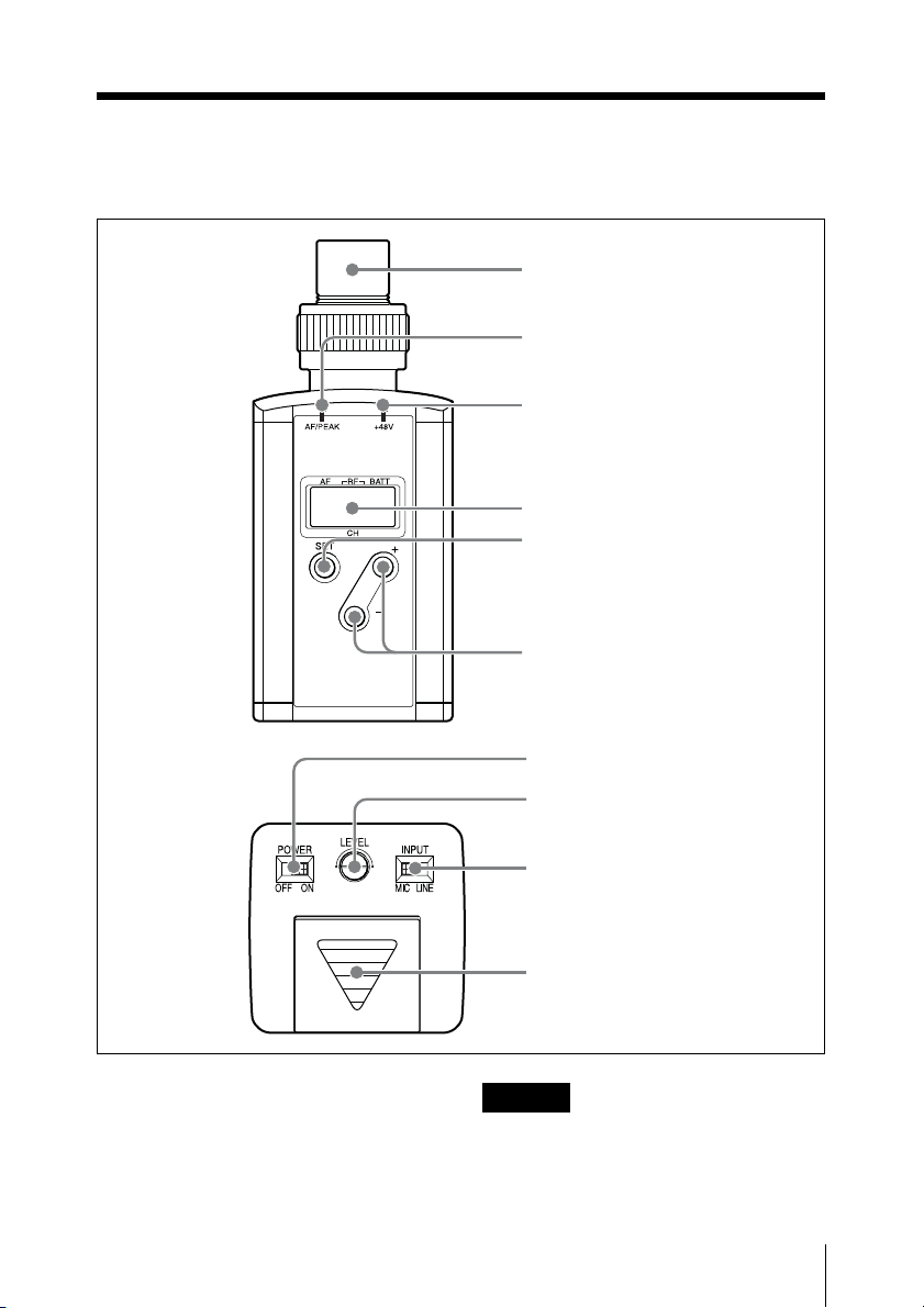
Parts Identification
1 Audio input connector
2 AF/PEAK indicator
3 +48V indicator
4 Display section
5 SET button
6 +/– buttons
7 POWER switch
a Audio input connector
Connects a microphone with an XLR-312C type output connector or an audio cable
with XLR-3-12C type connectors.
For details, see “System Configuration” (page 14).
8 LEVEL control
9 INPUT selector
0 Battery lid
Caution
When connecting a microphone or a cable
to the unit, be sure to turn the unit off.
Parts Identification
5
Page 6
b AF/PEAK (audio input/peak level)
E
indicator
Lights up green or red to indicate the
strength of the audio input signal level.
c +48V indicator
Lights up when the INPUT selector is set to
MIC position and the +48 V power supply
is enabled.
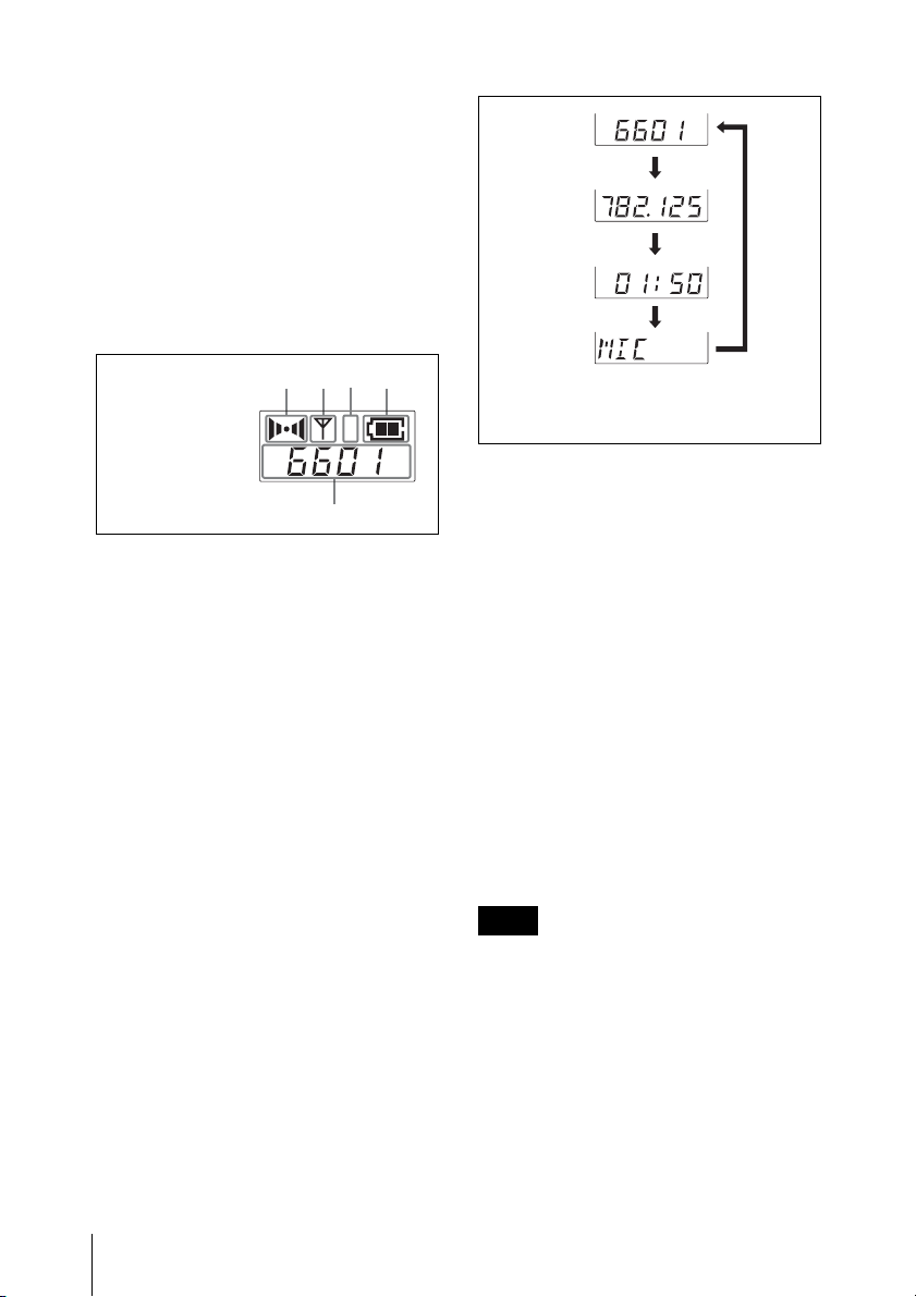
d Display section
C
D
B
A
Channel indication
E shows that of
the U66 model.
AF RFCHBATT
H
L
A AF indication
Appears whenever the input audio signal is
stronger than the reference level.
B RF (radio frequency) indication
Appears during signal transmission.
C RF power indication
Shows the RF output power setting.
For details, see “Setting the RF output power level”
(page 10).
D BATT (battery) indication
Shows the battery condition.
For details, see “Battery condition indication”
(page 7).
E CH (channel) indication
Shows transmitting channel. Each time you
press the SET button in transmitting mode,
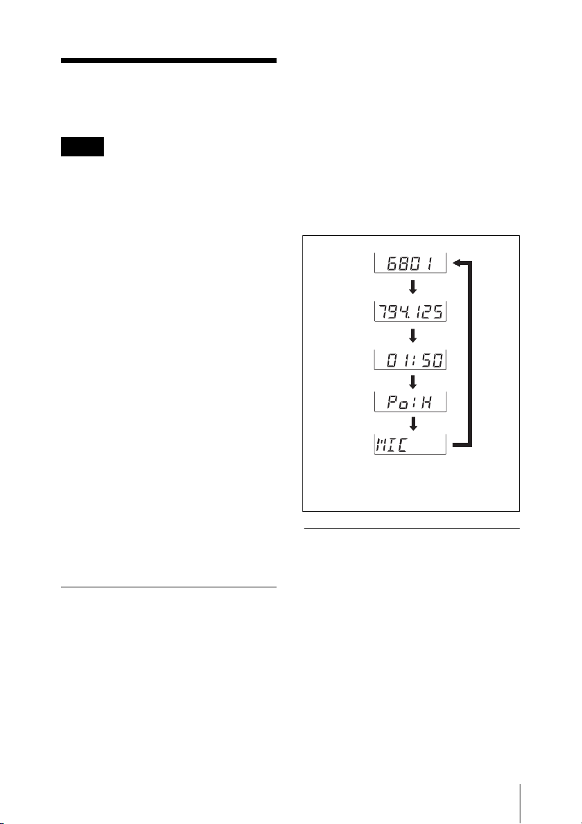
the indication changes as follows.
Transmission
channnel
Transmission
frequency
Accumulated
battery use
time
Input signal
setting
Channel/frequency indications show
those of the U66 model.
Press
the
SET
button.
e SET button
In transmitting mode, press this button to
change the parameters displayed in the CH
indication area.
The SET button is also used to enter the
setting mode and select the item to be set.
For details on the setting mode, see “Settings”
(page 9).
f +/– buttons
In setting mode, these buttons are used to
select the transmission channel or
frequency, RF output power setting, or to
turn on/off the +48 V power supply for the
connected microphone.
g POWER switch
Turns the power of the unit ON or OFF.
Note
Be sure to connect a microphone or a cable
from the audio mixer, etc. before turning
the POWER switch to ON.
h LEVEL (audio input level) control
Rotate to adjust the audio level input from
the audio input connector.
Parts Identification
6
For details on adjusting the audio input level, see
“Setting the audio input level” (page 11).
Page 7

i INPUT (input signal) selector
Set according to the equipment connected
to the audio input connector.
MIC: Select when a microphone is
connected.
LINE: Select when an audio mixer, etc. is
connected to the audio input
connector.
For details on the use of this selector, see “Setting
the audio input level” (page 11).
Note
To avoid producing noise, turn off the unit
before changing the INPUT selector
position from LINE to MIC when the
+48 V power supply is activated.
j Battery lid
Slide the battery lid to release the lock and
open the battery compartment.
The battery compartment accommodates
one 6LR61 (9 V) alkaline battery.
For details on how to insert the battery, see
“Inserting the battery” (page 8).
Power Supply
The WRT-8P can be powered by one
6LR61 (9 V) alkaline battery for about 1.5
to 4 hours of continuous operation at 25°C
(77°F). (Battery life depends on the RF
output power and +48 V power supply
settings.)
Details on the battery condition indication
and notes on battery are given below:
Battery condition indication
When you turn the power on, the battery
condition is shown by the BATT indication
in the display section.
When the indication starts to flash as
described in column 4 or 5 in the table
below, replace the battery with a new one.
Be sure to check the expiration date printed
on the new battery before using it.
BATT
indication
1Lights
2Lights
3Lights
4 Flashes Almost drained
Battery status
Good
Less than 50%
charged
Less than 20%
charged
Power Supply
7
Page 8
BATT
indication
5Flashes.
Other
indications in
the display
section do not
appear.
Battery status
Almost drained.
The unit does not
turn on when the
POWER switch is
turned ON.
Note
The indicated battery condition may not be
correct if the battery was not new when
installed. If you plan to use the unit for a
long period of time, it is recommended that
you replace the battery with a brand new
one.
Notes on battery
Battery may leak or explode if mistreated.
Be sure to follow these instructions.
• Be sure to install the battery with the
correct polarity.
• The battery is not rechargeable.
• When not using the unit for a long period
of time, remove the battery to avoid
leakage. If the battery does leak, clean all
leakage from the battery compartment
and the unit. Leakage left in the
compartment and the unit may cause poor
battery contact. If there seems to be poor
battery contact, consult your Sony dealer.
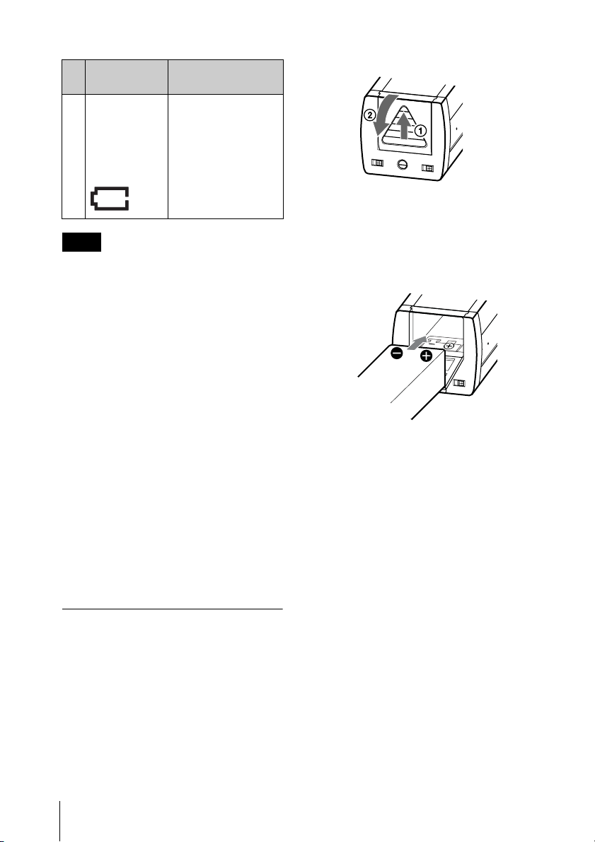
Inserting the battery
2 Insert a new 6LR61 (9 V) alkaline
battery matching its polarity markings
with those in the battery compartment,
then close the lid.
1 Slide the battery lid to release the lock
(1), and open the battery
compartment (2).
Power Supply
8
Page 9
Settings
To enter setting mode
Turn on the transmitter while pressing
down the SET button.
Notes
• The transmitter cannot transmit in setting
mode.
• Make sure that the channel selected on
the transmitter is the same as that selected
on the tuner being used in the same
system.
• Depending on the noise or interference
conditions, all selectable channels may
not be usable. If necessary, you can
determine usable channels by cycling the
channel selection through a number of
channels on the tuner with the transmitter
set to OFF. Those channels for which the
RF indicator on the tuner does not light
are usable.
• If there is a TV broadcasting station
nearby, do not use the station's channel.
• The transmitter may not operate correctly
if it is turned on immediately after being
turned off in setting mode. Wait for a few
seconds before turning the power on
again.
• The channel numbers and frequencies of
your transmitter are shown on the “Sony
Wireless Microphone System Frequency
List” supplied with this Operating
Instructions.
The transmitter enters setting mode and the
parameters that were displayed when the
unit was last turned off start to flash.
Each time you press the SET button, the
setting items are cyclically switched as
shown below.
Transmission
channnel
Transmission
frequency
Press
Accumulated
battery use
time
RF output
power setting
Input signal
setting
Channel/frequency indications show
those of the U66 model.
the SET
button.
Setting the transmission
channel
Entering setting mode
In setting mode, you can change the
transmission channel or frequency and RF
output power setting. You can also reset the
accumulated battery use time indication or
turn on/off the +48 V power supply for the
connected microphone.
The transmission channel can be selected
through either the channel number or the
frequency.
1 Set the transmitter to the setting mode.
2 Press the SET button repeatedly until
the channel number (or frequency)
indication appears.
3 Press the + or – button to select the
channel number (or frequency).
Settings
9
Page 10
Pressing the + button cycles the
indications in the order shown in the
tables in the pdf files “Sony Wireless
Microphone System Frequency List”
supplied with this Operating
Instructions.
Pressing the – button cycles the
indications in the opposite direction.
Hold down the + or – button to change
the channel number (or frequency)
faster.
4 Set the POWER switch to OFF to
complete the setting, or press the SET
button to set other items.
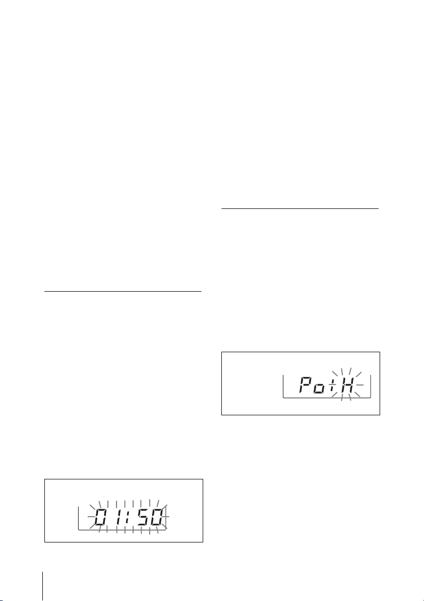
3 Press the – button.
The time indication resets to “00:00.”
While “00:00” is still displayed,
previous value can be resumed by
pressing the + button.
4 Set the POWER switch to OFF to
complete the setting, or press the SET
button to set other items.
The results are stored in memory. The
change becomes effective the next time you
turn on the transmitter by setting the
POWER switch to ON.
The results are stored in memory. The
change becomes effective the next time you
turn on the transmitter by setting the
POWER switch to ON, and the transmitter
enters transmit mode with the selected
transmission channel.
Resetting the accumulated
battery use time indication
The accumulated battery use time is the
total time (in hours and minutes) that the
battery has been used. It is recorded
whenever the transmitter is on.
Reset the indication to “00:00” whenever
you replace the battery.
1 Set the transmitter to the setting mode.
2 Press the SET button repeatedly until
the accumulated time indication
appears.
Setting the RF output
power level
You can select the RF output power level
from “H” (250 mW) or “L” (50 mW) in
setting mode.
1 Set the transmitter to the setting mode.
2 Press the SET button repeatedly until
the RF output power indication
appears.
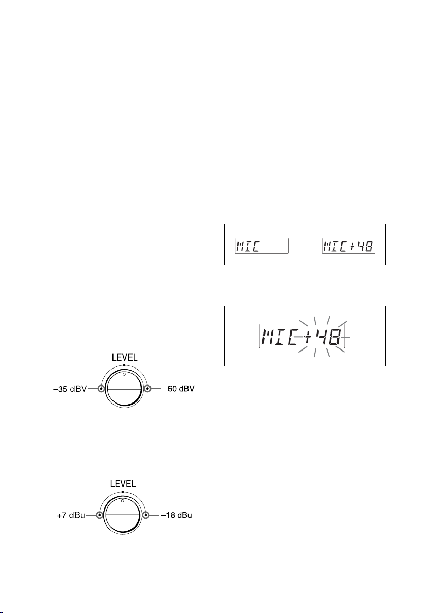
Current RF
output power
setting
3 Press the + button to select “H” (250
mW), or press the – button to select
“L” (50 mW).
4 Set the POWER switch to OFF to
complete the setting, or press the SET
button to set other items.
10
The results are stored in memory. The
change becomes effective the next time you
turn on the transmitter by setting the
POWER switch to ON, and the transmitter
Settings
Page 11
enters transmit mode with the selected RF
output power level.
Occasional lighting of the AF/PEAK
indicator in red is acceptable.
Setting the audio input
level
You can adjust the audio input level,
regardless of the INPUT selector position.
1 Set the INPUT selector according to
the equipment connected to the audio
input connector.
When a microphone is connected to
the audio input connector, set the
selector to MIC position; when a
mixer, etc. is connected, set it to LINE
position.
2 Turn the LEVEL control so that the
AF/PEAK indicator lights up green
continuously.
When the INPUT selector is set
to MIC position
Reference input level can be adjusted
within a range shown below.
When the INPUT selector is set
to LINE position
Reference input level can be adjusted
within a range shown below.
Setting the +48 V power
supply
You can set the +48 V power supply for the
electric condenser microphone in setting
mode.
1 Set the transmitter to the setting mode.
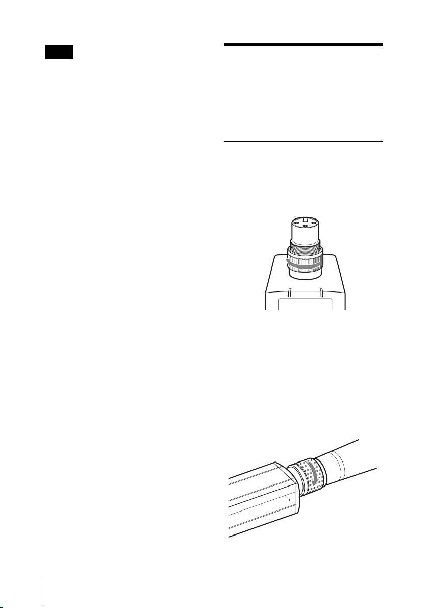
2 Press the SET button repeatedly until
the “MIC” or “MIC+48” indication
appears.
or
3 Press the + button to select “MIC+48,”
or press the – button to select “MIC.”
Select “MIC+48” to supply the +48 V
power to the connected microphone
when the INPUT selector is set to MIC
position in transmit mode; select
“MIC” to cancel the +48 V power
supply.
4 Set the POWER switch to OFF to
complete the setting, or press the SET
button to set other items.
The results are stored in memory. The
change becomes effective the next time you
turn on the transmitter by setting the
POWER switch to ON, and the transmitter
enters transmit mode with the selected
power supply setting.
Settings
11
Page 12
Note
+48 V power supply setting can be
performed when the INPUT selector is set
to either LINE or MIC. However, +48 V
power supply takes place when next time
the transmitter is turned on and the INPUT
selector is set to MIC.
Attachment and
Insertion
Procedures
Attaching a microphone or
a cable
1 Turn the connector ring clockwise.
2 Push the microphone or cable
connector (XLR-3-12C type
connector) against the audio input
connector of the unit until it is fully
inserted.
Attachment and Insertion Procedures
12
3 Turn the connector ring
counterclockwise to secure the latch.
Page 13
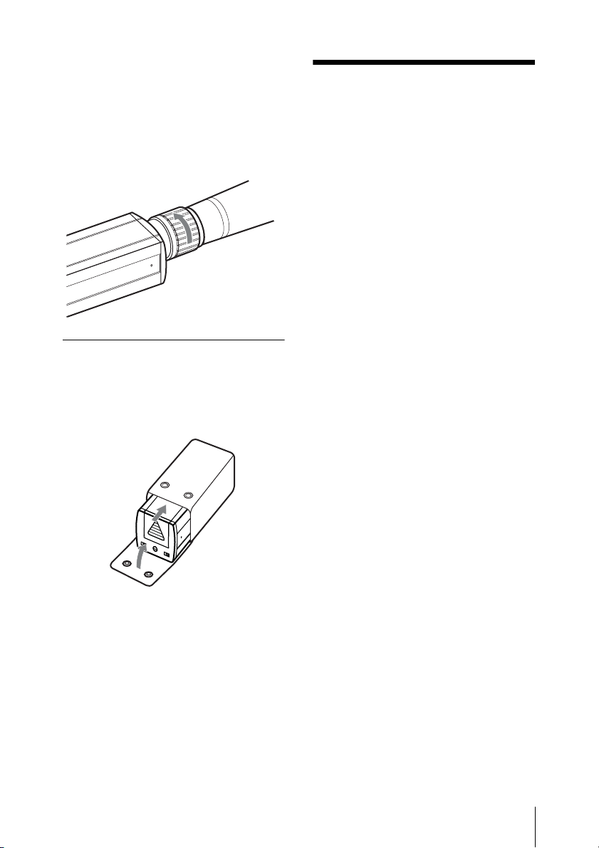
Detaching a microphone or a
cable
Turn the connector ring clockwise to loosen
the latch, then pull out the microphone or
cable connector.
Inserting into the supplied
soft case
Insert the unit into the supplied soft case
with the rear side up, and close the flap.
Notes on
Microphone
System
Operations
• To operate with two or more channels,
maintain a distance of at least 30 cm (one
ft.) between each pair of transmitters.
• Ensure that the tuners set to channels not
being used are either turned off or set to
the minimum output level.
• When turning the transmitter on or off, to
keep the noise to a minimum, turn down
the audio output level from the tuner or
mixer to a minimum level.
• Turning on the transmitter without
checking the channel selection first may
interfere with the operation of other
microphones/transmitters, if the current
setting is already being used.
• To prevent noise generation, set the RF
output power level to L (50 mW) when
multiple channels are used
simultaneously, and keep the transmitters
at least 6 m (20 feet) away from the
antennas.
• When there is a strong interference signal
around the microphone system, such as
an interference caused by an active
cellular phone, noise may occur on the
microphone system.
• Before attaching/detaching the
microphone or cable, turn down the
volume of the equipment connected to
the tuner. Otherwise, noise will be
produced.
Notes on Microphone System Operations
13
Page 14
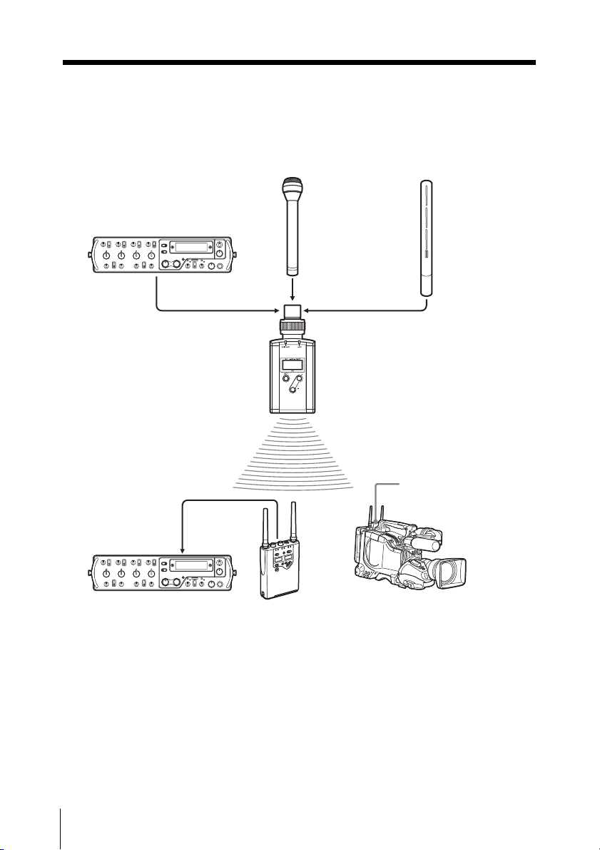
System Configuration
The illustration below shows the typical system configuration.
F-112 Dynamic
Microphone
DMX-P01
Digital Portable
Mixer
Output cable
(supplied with
the WRR861B/862B)
XLR type audio
cable (not
supplied)
WRT-8P
ECM-674/678
Electret
Condenser
Microphone
WRR-855B/861B/862B
UHF Synthesized
Diversity Tuner
System Configuration
14
DMX-P01 Digital
Portable Mixer
WRR-861B/862B UHF
Synthesized Diversity
Tuner
PDW-510/510P/530/
530P XDCAM
Camcorder
Page 15
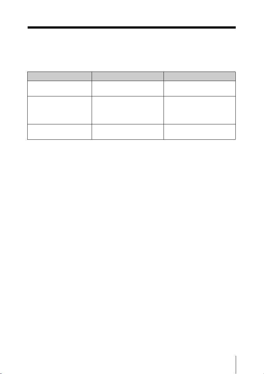
Error Messages
When a problem occurs, one of the following error messages may appear on the display.
Messages Meanings Remedy
ERROR 11 An error has occurred in the
backup memory data.
ERROR 21 The PLL synthesized circuit
is abnormal.
ERROR 31 The battery voltage exceeds
the allowable limit.
Contact your Sony dealer.
Turn off the unit and turn it
on again. If the message
appears again, contact your
Sony dealer.
Use the specified battery.
Error Messages
15
Page 16
Specifications
Transmitter and modulator
section
Oscillator
Crystal controlled PLL synthesizer
Carrier frequencies
566.125-589.875MHz
(U3032 Model)
638.125-661.875MHz
(U4244 Model)
Operating frequency band
24 MHz
RF power output
250 mW/50 mW ERP
Tone signal
32.768 kHz
Battery condition signal
32.782 kHz
Pre-emphasis
50 µs
Deviation
±10 kHz
(-60 dBV, 1 kHz input, MIC)
±10 kHz
(-18 dBu, 1 kHz input, LINE)
Power section
Power requirements
9.0 V DC (one 6LR61 alkaline
battery)
Battery life (at 25°C (77°F ) with a Sony
6LR61 alkaline battery)
Approx. 1.5 hours (250 mW, +48 V
on)
Approx. 2.5 hours (50 mW, +48 V
on)
Approx. 2.5 hours (250 mW)
Approx. 4 hours (50 mW)
General
Operating temperature
0 C to 50°C (32°F to 122°F)
Storage temperature
–30°C to 60°C (–22°F to 140°F)
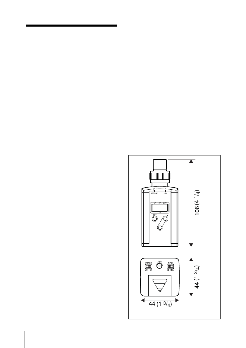
Dimensions
1) 0 dBV=1 Vrms
2) 0 dBu=0.775 Vrms
Maximum deviation
±40 kHz
Audio input attenuation
0 to 25 dB (MIC, LINE)
Audio input pad
40 dB (LINE)
Frequency response
50 to 18,000 Hz
Signal-to-noise ratio
60 dB or more (A-weighted,
modulation frequency 1 kHz,
with ±10 kHz deviation at
tuner)
Specifications
16
Unit: mm (inches)
Page 17

44 × 106 × 44 mm (13/4 × 41/4 ×
3
/4 inches) (w/h/d)
1
Mass Approx. 230 g (8 oz) (including
battery)
Supplied accessories
Operating Instructions (1)
Sony Wireless Microphone System
Frequency List (1)
Soft case (1)
Design and specifications are subject to
change without notice.
Specifications
17
Page 18

Sony Corporation
Printed in
Japan
 Loading...