

Page 1
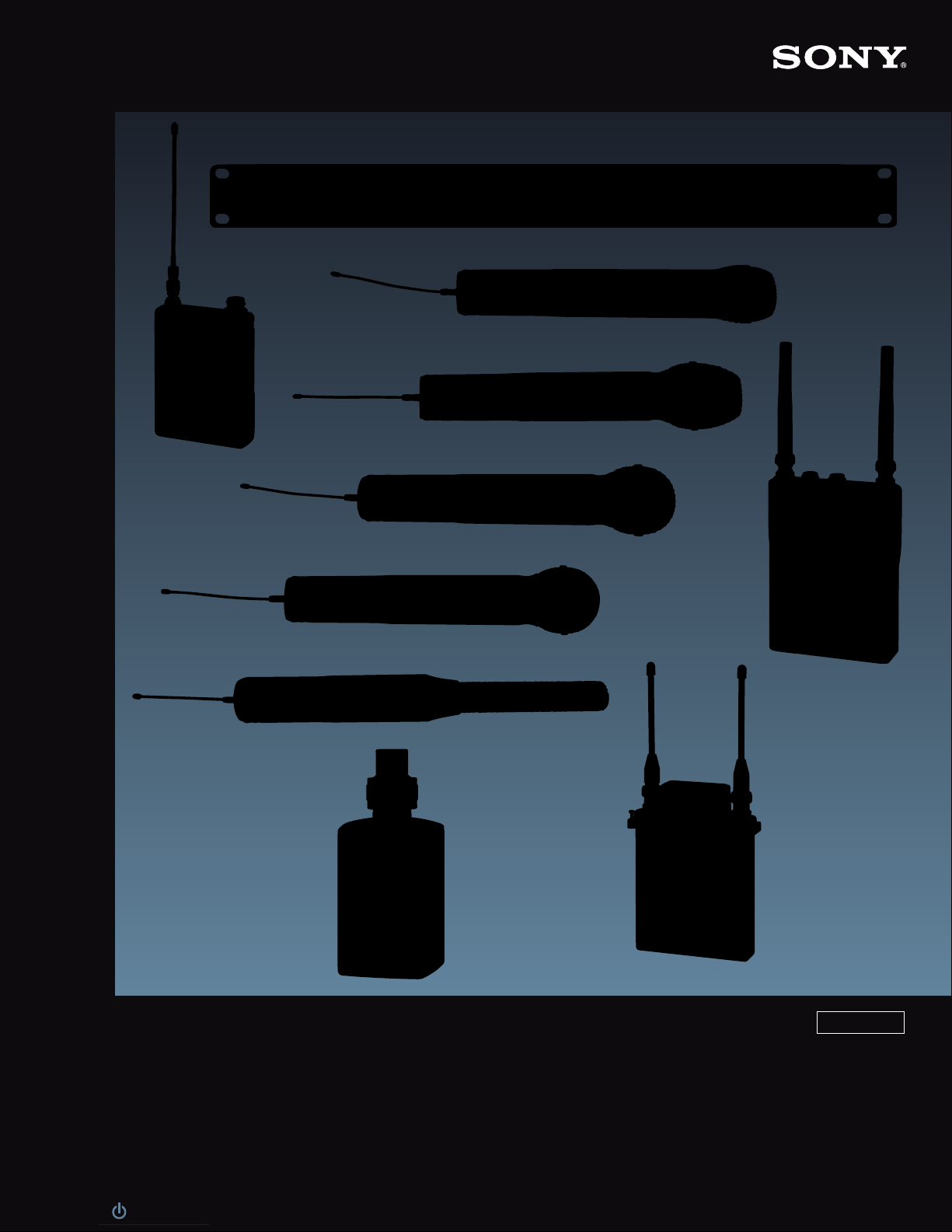
UHF Synthesized
click:
Wireless Microphone System
U, AU
sony.com/proaudio
Page 2
Superb Performance
and Reliability
in an Affordable Package
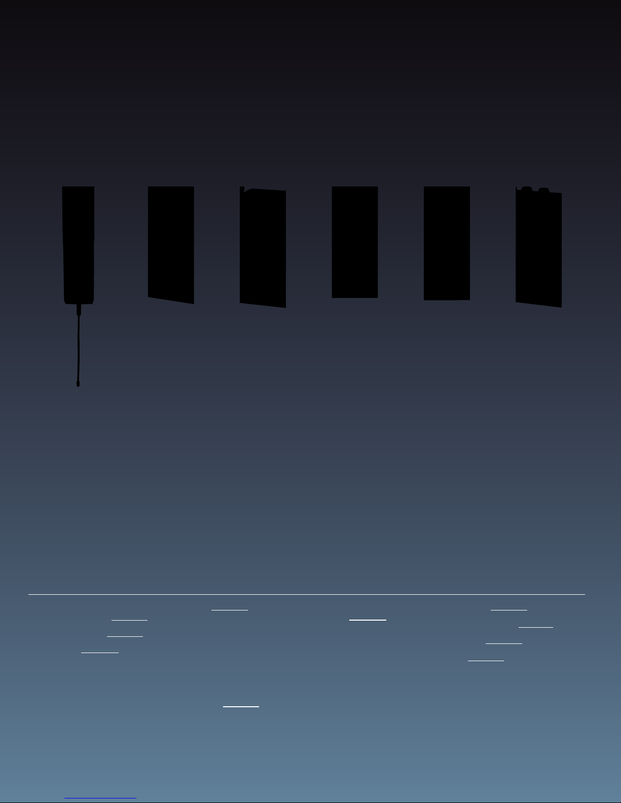
Since its introduction,the unique qualities of the Sony WL-800 Series UHF synthesized
wireless microphone system have been proven in many different applications. It has
been particularly successful in critical applications such as broadcasting and
production,where its low noise,wide audio dynamic range, stable RF transmission and
reception, and high reliability have been vital factors.
Sony has continually enhanced its WL-800 Series to fulfill the ever-increasing needs for
wireless operations. Offering a broad range of choices, this family presents a solution to
virtually any wireless microphone application from the very simple to the most
sophisticated. Such applications include ENG and EFP location, conference and
entertainment,TV studio production,theater, and live performance to name just a few.
A variety of options are also made available so that systems are established to suit
different operational needs.
The Sony WL-800 Series UHF synthesized wireless microphone system offers a perfect
choice for all levels of operational and budgetary needs*.
*Sony WL-800 Series Wireless Microphone System and UWP Series Wireless Microphone System are not compatible.
Contents
Sony Wireless Microphone
Common Features 3
System Examples 4
Transmitters 6
• WRT-847A/847B
• WRT-807A/807B
• WRT-8P
• WRT-8B
• WRT-822A/822B
Tuners 10
• WRR-862A/862B
• WRR-855S
• WRR-861A/861B
• MB-8N
• WRU-8N
• MB-X6
• WRU-806A/806B
Distributors and
Antenna 13
• WD-850
• AN-820A
Optional
Accessories 14
• ECM-88 Series
• ECM-77 Series
• ECM-66BC
• ECM-44 Series
• ECM-166BC
• ECM-322BC
• BTA-801
• DWA-01D
• CA-WR855
• A-8278-057-B
• EC-1.5CF
• DMX-P01
Frequency Lists 16
Feature Comparisons 17
Specifications 19
Appendix 22
• Multi-channel Simultaneous Operations
• Tuner and Camcorder Combinations
• Attaching to Camcorders
2
Page 3
Sony Wireless Microphone Common Features
AF BATT
RF
GP
CH
GP CH
BATT
PLL Synthesized System
Phase Locked Loop (PLL) frequency synthesized systems
are employed both in transmitters and receivers, assuring
carrier stability and providing easy access to multiple
frequencies. These PLL controlled systems provide highly
stable, selectable frequencies to be generated in
increments of 125 kHz. Users may choose from 188
frequencies on USA type models, and 102 frequencies on
AU models.
Space Diversity Reception System
A space diversity reception system is used to eliminate
signal dropout. Dual antenna inputs and reception circuits
incorporated in the diversity system receive signals over
two different paths and select the stronger signal as the
output. This switching operation is undetectable on the
audio output of the receivers.
Pre-programmed Frequency Groups
Optimum combinations of calculated and practically
tested intermodulation-free frequencies are stored in each
receiver to make it easy to choose the correct frequencies
for simultaneous multi-channel operation. These
frequencies are arranged in groups, with each group preprogrammed to allow virtually interference free operation.
Multiple Information on Easy-to-read LCD and
LED
Most receivers and transmitters feature easy-to-read LCD
panel and LED indicators, which provide extensive
information on the operating conditions.
Most receivers will display the RF-input level, audio-output
status, current channel number and frequency, and
battery status of the transmitter.
Most transmitters do in essence have the same information
available in the receivers such as audio-input and RFoutput status, current channel number and frequency,
input attenuation setting, and accumulated battery
operating time.
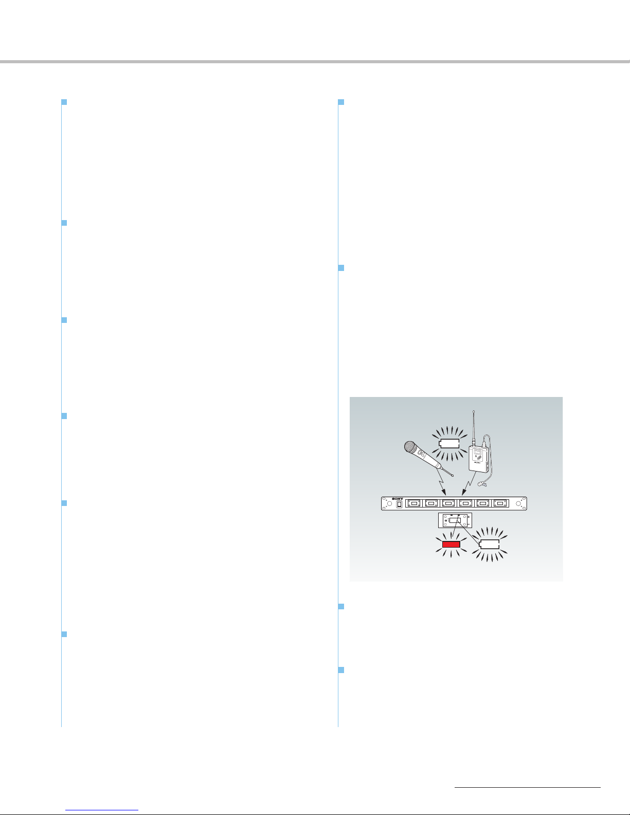
Remote Battery Alarm on Receiver
For added assurance of continued operation,users can
monitor the battery reserves of handheld, body pack and
plug-on transmitters. Remaining battery life is indicated on
both the transmitter and receiver, with additional
indication approximate one hour* before the battery goes
dead. On the receiver, the battery indicator on the LCD
and LED displays also flash, helping to avoid the chance of
battery failure at a critical moment.
*This may vary depending on the operational environment.
Advanced Filtering
The Sony wireless units all employ Helical, Ceramic and/or
SAW (Surface Acoustic Wave) filters as appropriate. This
offers stable reception and superb audio quality, and also
enables the unique miniaturization seen in most of the
Sony products.
Tone Squelch Circuitry
The wireless microphone transmitters also transmit a 32.768
kHz pilot-tone signal along with the audio signal. In the
receivers, a squelch circuit is present, and the audio signal
is only output when the tone signal has been correctly
received.
This squelch function is designed to virtually prevent the
output of unwanted signals or noise from other signal
transmissions in the air,as well as the RF noise and popping
noise that occur when the transmitter is power on or off.
Compander System for Wide Dynamic Range
and Low Noise
A compander (compressor/expander) system is included
for improved audio dynamic range and low noise and
interference. The time constants for attack and release
times are carefully chosen in the various transmitters to
match the application, ensuring minimized noise level
while providing smooth and superb audio quality.
Consistent RF Power Output
A DC-DC convert circuit built into the power supply section
of microphones/transmitters assures consistent output
power over the life of the batteries.
Channel Setting Back Up
Each unit has a convenient memory back up for storing
operating frequencies. When the power switch is turned
on, the previous channel setting is automatically recalled
and displayed.
3
Page 4
System Examples
UHF Antenna
AN-820A
Transmitter x6
Tuner Unit
WRU-806B
Tuner Base Unit
MB-X6
UHF Antenna
AN-820A
Tuner Unit
WRU-8N
Tuner Base Unit
MB-8N
Transmitter x16
UHF Antenna
AN-820A
U
Transmitter x16
T
Tuner Base Unit
MB-X6
Tuner Unit
WRU-806B
Antenna Divider
WD-850
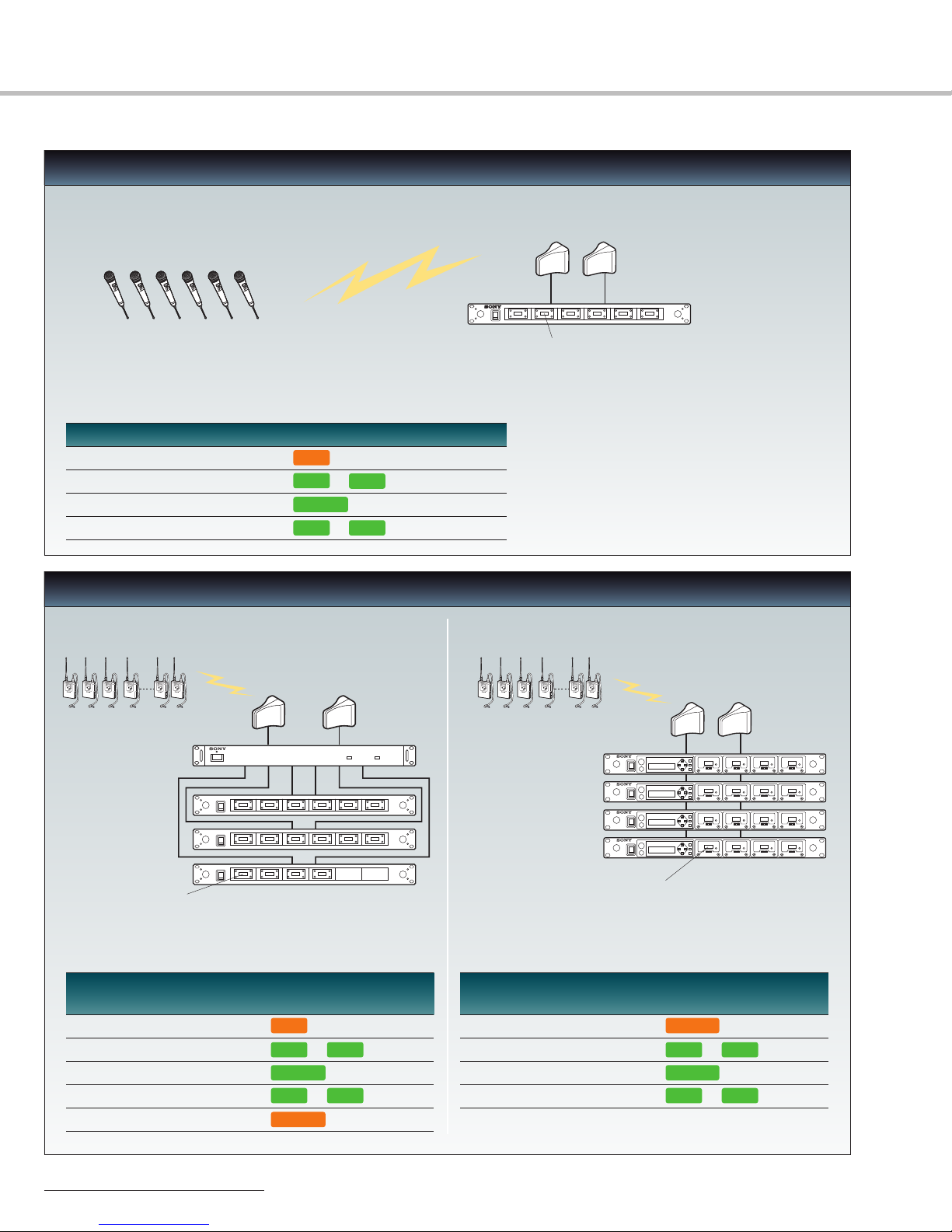
6-channel Simultaneous Operation
MB-X6 System
Required Components
Operation in TV 30-33 or TV 42-45 Channels
Model Number Model Name Operable TV Channel Units
MB-X6 Tuner Base Unit 30-69 1
WRU-806B Tuner Unit 30-33 or 42-45 6
AN-820A UHF Antenna L (30-45) 2
WRT Series Transmitter 30-33 or 42-45 6
16-channel Simultaneous Operation
MB-X6 System MB-8N* System
Required Components
Operation in TV 30-33 or TV 42-45 Channels
Model Model Operable TV Units
Number Name Channel
MB-X6 Tuner Base Unit 30-69 3
WRU-806B Tuner Unit 30-33 or 42-45 16
AN-820A UHF Antenna L (30-45) 2
WRT Series Transmitter 30-33 or 42-45 16
WD-850 Antenna Divider F (30-69) 1
4
Required Components
Operation in TV 30-33 or TV 42-45 Channels
Model Model Operable TV Units
Number Name Channel
MB-8N Tuner Base Unit F (30-69) 4
WRU-8N Tuner Unit 30-33 or 42-45 16
AN-820A UHF Antenna L (30-45) 2
WRT Series Transmitter 30-33 or 42-45 16
* Original MB-8N supports Channel 62-69 operation.
Channel 30-69 operation requires new MB-8N F model.
Page 5
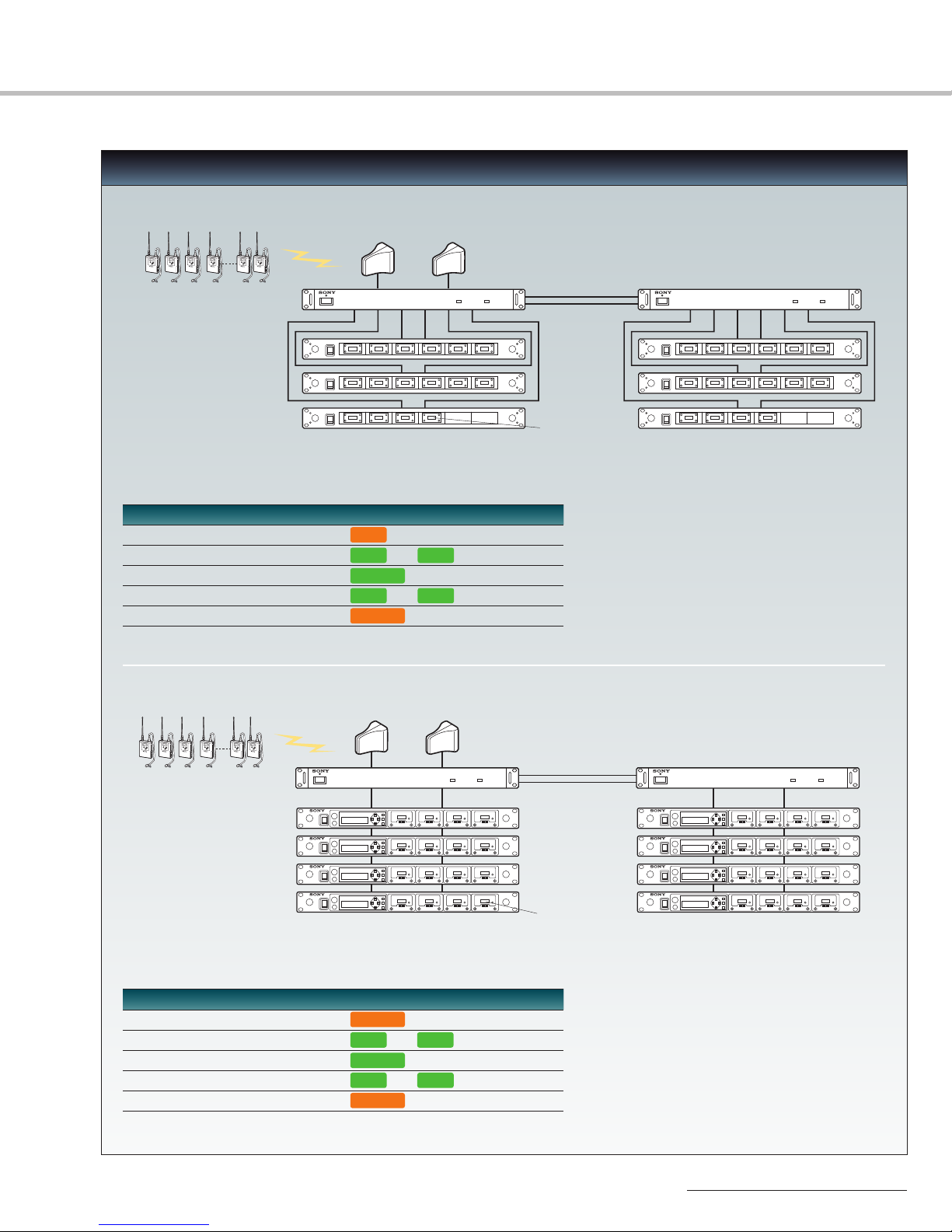
32-channel Simultaneous Operation
UHF Antenna
AN-820A
Transmitter x32
Tuner Base Unit
MB-X6
Tuner Unit
WRU-806B
Antenna Divider
WD-850
Transmitter x32
UHF Antenna
AN-820A
Antenna Divider
WD-850
Tuner Unit
WRU-8N
Tuner Base Unit
MB-8N
MB-X6 System
Required Components
Operation in TV 30-33 and TV 42-45 Channels
Model Number Model Name Operable TV Channel Units
MB-X6 Tuner Base Unit 30-69 6
WRU-806B Tuner Unit 30-33 and 42-45 32
AN-820A UHF Antenna L (30-45) 2
WRT Series Transmitter 30-33 and 42-45 32
WD-850 Antenna Divider F (30-69) 2
MB-8N* System
Required Components
Operation in TV 30-33 and TV 42-45 Channels
Model Number Model Name Operable TV Channel Units
MB-8N Tuner Base Unit F (30-69) 8
WRU-8N Tuner Unit 30-33 and 42-45 32
AN-820A UHF Antenna L (30-45) 2
WRT Series Transmitter 30-33 and 42-45 32
WD-850 Antenna Divider F (30-69) 2
* Original MB-8N supports Channel 62-69 operation. Channel 30-69 operation requires new MB-8N F model.
5
Page 6
Transmitters
100 Hz
1 kHz
6 kHz
0∞
90∞
180∞
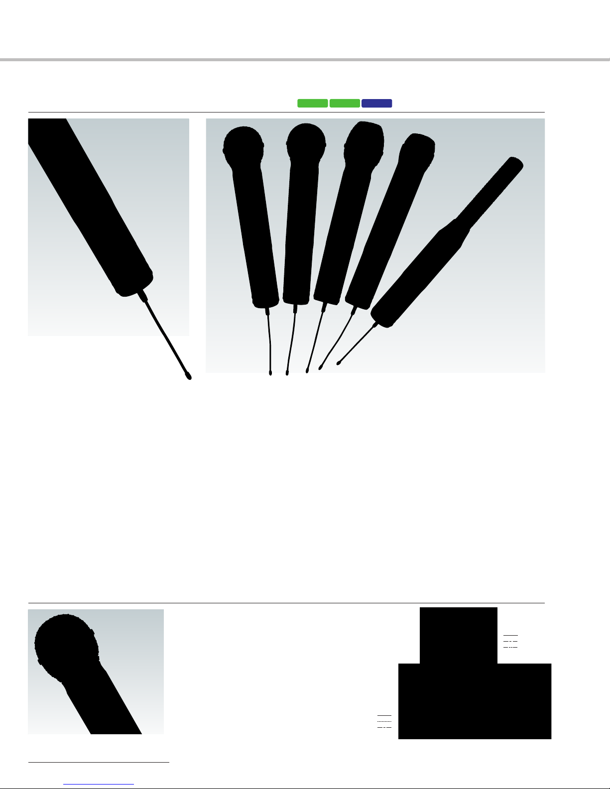
WRT-847A/847BUHF Synthesized Transmitter Unit
WRT-847A/847B
U30/32 U42/44
AU66
Photo shows WRT-847A/847B with optional
microphone capsules attached.
• Five optional microphone capsules are available, providing a choice of characteristics that suit a range of different
applications. Microphone capsules are available individually.(One head is required for the WRT-847A/847B to function.)
• Audio compander time constant is switchable to suit different capsules
• Selectable RF output level: 10 mW for simultaneous multi-channel operation and 50 mW for long distance operation
• Audio gain and attenuation setting from +9 dB to -12 dB in 3 dB steps
• Lockable external power switch (ON/OFF)
• Two AA-size (LR6) alkaline batteries provide approximately eight hours of continuous operation
CU-F780Capsule Unit
• Dynamic microphone capsule with super
cardioid polar pattern
• Uses the same high quality edgewise winding
CCAW voice coil that is employed in the
acclaimed Sony F-780 wired microphone
• Designed for vocal applications including
live music performance
• Frequency response: 50 Hz to 18 kHz
• Max.SPL: 142 dB SPL*
(at audio gain -12 dB)
• Dimensions: ø 2 1/8 x 3 5/8 inches
(ø 51 x 90 mm)
• Weight: 6.3 oz (180 g)
* 0 dB SPL=2 x 10⁻⁵Pa
Response (dB)
Uni-directional
Frequency (Hz)
6
Page 7

CU-G780Capsule Unit
100 Hz
1 kHz
6 kHz
0∞
90∞
180∞
200 Hz
1 kHz
5 kHz
0∞
90∞
180∞
100 Hz/1 kHz
6 kHz
0∞
90∞
180∞
250 Hz
1 kHz
4 kHz
0∞
90∞
180∞
CU-E700Capsule Unit
• Dynamic microphone capsule with super
cardioid polar pattern
• Special design,based on the capsule of F-780
microphone, to cope with high sound pressure
level vocals and incorporating outstanding
feedback rejection
• Designed for vocal use
• Frequency response: 50 Hz to 20 kHz
• Max.SPL: 142 dB SPL*
(at audio gain -12 dB)
• Dimensions: ø 2 1/8 x 3 5/8 inches
(ø 51 x 90 mm)
• Weight: 6.3 oz (180 g)
* 0 dB SPL=2 x 10⁻⁵Pa
• Electret condenser microphone capsule
with super cardioid polar pattern
• Smooth frequency response for natural
sound reproduction
• Suitable for critical vocal and speech
applications
• Frequency response: 50 Hz to 18 kHz
• Max.SPL: 142 dB SPL*
(at audio gain -12 dB)
• Dimensions: ø 2 1/8 x 3 7/8 inches
(ø 51 x 98 mm)
• Weight: 6.0 oz (170 g)
* 0 dB SPL=2 x 10⁻⁵Pa
Uni-directional
Response (dB)
Frequency (Hz)
Uni-directional
Response (dB)
Frequency (Hz)
CU-E672Capsule Unit
CU-F117Capsule Unit
• Electret condenser microphone capsule
with hyper cardioid polar pattern
• A wide variety of applications in newsgathering,sports events and interviews
•
The supplied windscreen reduces wind noise and
popping
• Frequency response: 50 Hz to 16 kHz
• Max.SPL: 120 dB SPL*
• Dimensions: ø 1 1/2 x 6 7/8 inches
(ø 37 x 172 mm)
• Weight: 5.3 oz (150 g)
•
Supplied accessory: Urethane windscreen (1)
* 0 dB SPL=2 x 10⁻⁵Pa
• Dynamic microphone capsule with omnidirectional polar pattern
• Superb rejection of wind noise and popping
• Designed for interview applications
• Frequency response: 50 Hz to 15 kHz
• Max.SPL: 142 dB SPL*
(at audio gain -12 dB)
• Dimensions: ø 1 3/4 x 4 1/4 inches
(ø 44 x 105 mm)
• Weight: 6.0 oz (170 g)
•
Supplied accessory: Urethane windscreen (1)
* 0 dB SPL=2 x 10⁻⁵Pa
Uni-directional
Response (dB)
Omni-directional
Response (dB)
Frequency (Hz)
7
Page 8
Transmitters
20 50 100 200 500 1k 2k 5k 10k 20k Hz
0˚
90˚
180˚
20
10
0
-10
-20
-30
0˚
30˚
60˚
90˚
120˚
150˚
180˚
150˚
120˚
90˚
60˚
30˚
0dB
-20
-10
-5
-15
100 Hz
1 kHz
6 kHz
0∞
90∞
180∞
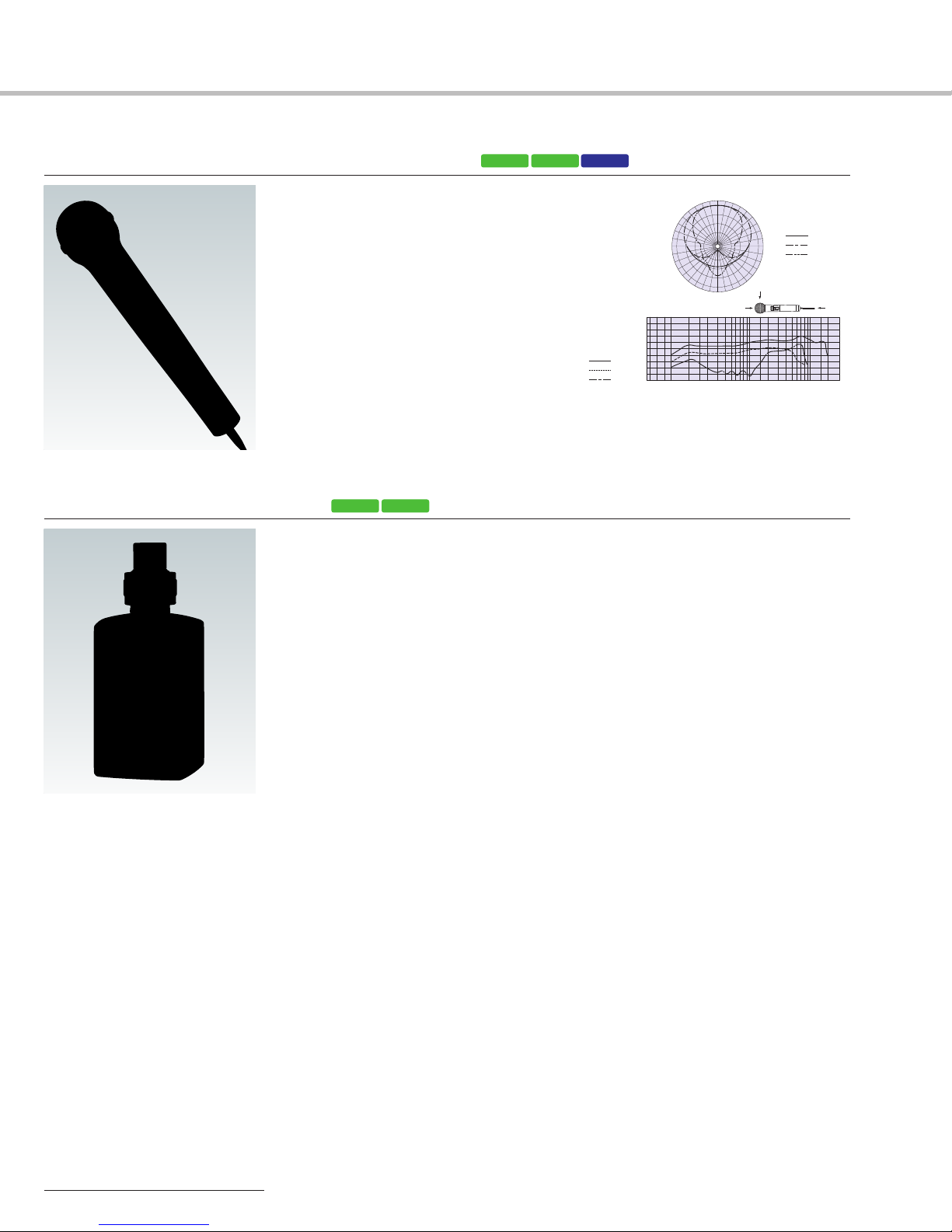
WRT-807A/807BUHF Synthesized Wireless Microphone
• Uses the same dynamic microphone
capsule that is employed in the F-780
professional wired microphone
• High quality sound for vocals – powerful,
crisp and clear
• Single AA-size (LR6) alkaline battery provides
continuous operation for approximately five
hours
• Lockable external power switch (ON/OFF)
WRT-8PUHF Synthesized Transmitter
• Converts a wired microphone to a wireless microphone via an XLR-type connector
• Compact and lightweight metal body provides high durability and good balance
• 250 mW high RF output power for stable long-distance transmission
• Selectable RF output power: 250 mW/50 mW
• +48 V power supply capability
• Switchable input level: MIC/LINE
• Attenuator function allows adjustment of the audio-input level
• A backlit LCD provides extensive information
• Optimized balance when combined with the F-112 dynamic microphone
U30/32 U42/44
with compatible microphones
U30/32 U42/44 AU66
Uni-directional
Response (dB)
Frequency (Hz)
8
Page 9
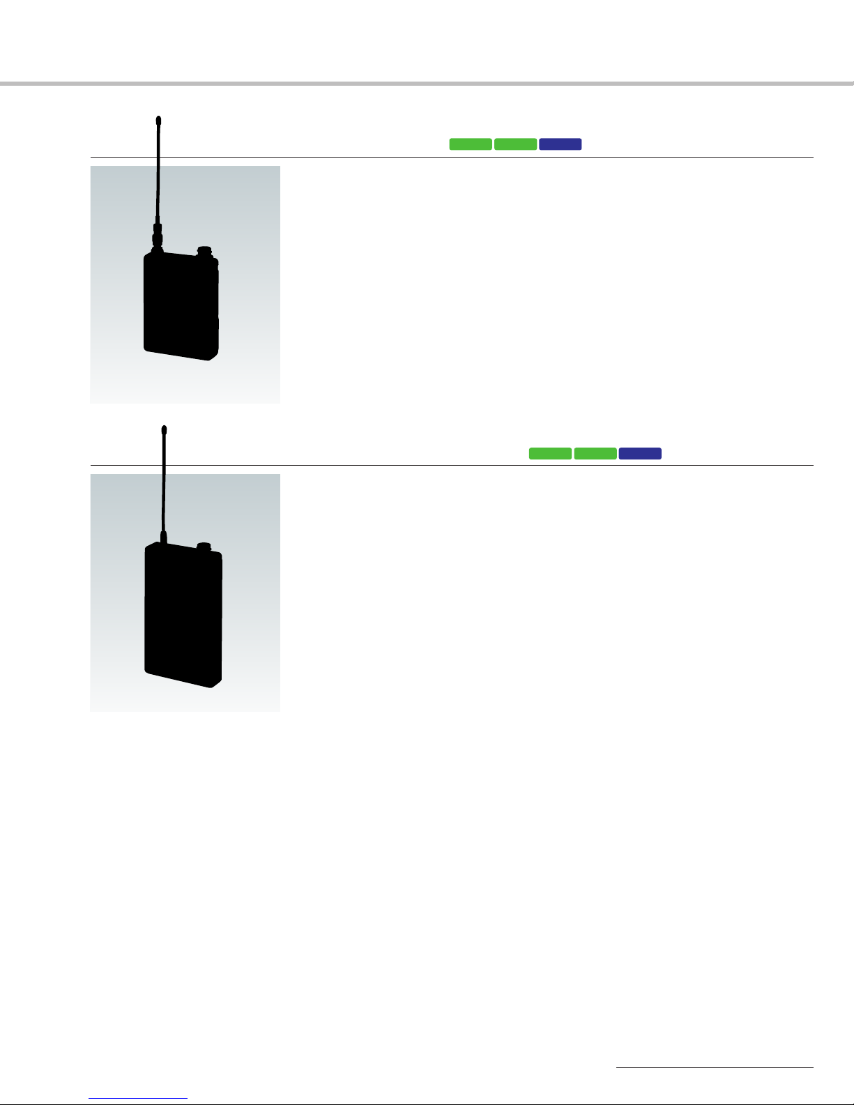
WRT-8BUHF Synthesized Transmitter
• Ultra compact and lightweight: 140 g including batteries (not supplied)
• Selectable RF power output: 50 mW output for long-distance transmission or 10 mW
output for multi-channel simultaneous operation
• Switchable input level (LINE or MIC level) and attenuator level control knob
• SMA-J type, removable antenna
• Approximately 13 hours of continuous operation with two AA-size alkaline (LR6)
batteries at 10 mW output (not supplied)
• Accepts the output of professional lavalier microphones equipped with a Sony
4-pin connector (SMC9-4P)
U30/32 U42/44 AU66
WRT-822A/822BUHF Synthesized Transmitter
• Approximately six* hours of continuous operation with two AA-size (LR6) alkaline
batteries (not supplied)
• Compact,lightweight,magnesium alloy body
• 20** mW RF power output
• Accepts the output of professional lavalier microphones equipped with a Sony
4-pin connector (SMC9-4P)
* In the case of the WRT-822B (USA type).
The WRT-822A (AU type) offers approximately eight hours of continuous operation.
** In the case of the WRT-822B (USA type).
The WRT-822A (AU type) offers 10 mW power output.
U30/32 U42/44 AU66
9
Page 10
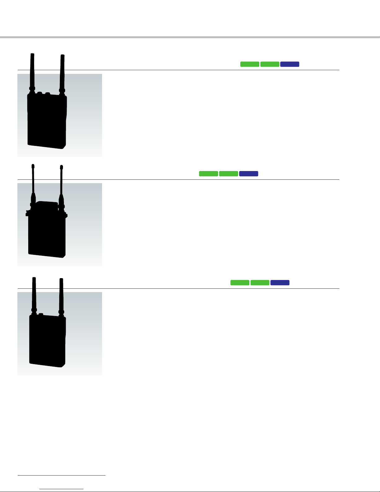
Tuners
WRR-862A/862B UHF Synthesized Dual Diversity Tuner
• Receives two independent RF signals simultaneously on two separate channels
• Compact and lightweight: 14.1 oz (400 g) including batteries (not supplied)
• Two way powering: Internal battery operation or operation on external power from
Sony camcorders via the supplied cable
• A red LED starts flashing approximately one* hour before the transmitter’s battery is
exhausted
• Two Sony 4-pin (SMC9-4S) audio output connectors are provided on the top panel
• Switchable RF squelch levels: ON (5 dBµ,10 dBµ, 15 dBµ) or OFF
• Stereo mini jack for monitoring the output sound (switchable: Tuner 1/Tuner 2/Mixed)
with headphones
• Monitor volume control provided
*This time may vary depending on the operational environment.
WRR-855S UHF Synthesized Diversity Tuner
• Space Diversity Tuner for camcorder use
• Easily mounts onto Sony HDCAM
MPEG IMX
adapter
• Compact and lightweight design: 11 oz (280 g)
• A D-sub 15-pin connector for audio output to a Sony professional camcorder and for
receiving its power supply from the camcorder
• A LCD provides various information such as RF input level and audio output status
®
camcorders without need for audio/power cables or a mounting
®
/XDCAM®HD422/Digital Betacam®/XDCAM SD/
U30/32 U42/44 AU66
AU66U30/32 U42/44
WRR-861A/861B UHF Synthesized Diversity Tuner
• Single-channel version of the WRR-862A/862B
• Two way powering: Internal battery operation or operation on external power from
Sony camcorders via the supplied cable
• A red LED starts flashing approximately one* hour before the transmitter’s battery is
exhausted
• Switchable RF squelch levels: ON (5 dBµ,10 dBµ, 15 dBµ) or OFF
• Stereo mini jack for monitoring the output sound
• Monitor volume control provided
*This time may vary depending on the operational environment.
AU66U30/32 U42/44
10
Page 11

MB-8N*Tuner Base Unit
F(U30-69)AU66
• Accommodates up to four WRU-8N tuner modules in a 1U
high,rack-mountable chassis
• Built-in antenna-divider allows four MB-8Ns to be
daisy-chained for up to 16-channel simultaneous
operation without the need of an external divider.
• Control settings such as audio output levels,RF squelch
levels, attenuator levels for the installed tuner modules,and
power supply setting (ON/OFF) for the connected AN820A antennas are available from the front panel
• An auto channel assignment function for extra receiver
modules with self-detection and skipping of unusable
channels
• A headphone monitor jack and level control knob are
located on the front panel. The monitor output can be
selected from individual WRU-8N tuner modules or mixed
sound from all installed modules
• Computer-based remote control is also possible via a
standard Ethernet (10BASE-T) connection. The supplied
software allows full monitoring of the operating status and
all control settings available on both the MB-8N and
WRU-8N. Multi-channel settings can be stored as files
* Original MB-8N supports Channel 62-69 operation. Channel 30-69 operation
requires new MB-8N F model.
Front Panel: MB-8N with four WRU-8N tuner units installed
Rear Panel
MB-8N supplied software GUI
WRU-8NUHF Synthesized Tuner Unit
U30/32
U42/44 AU66
• Plug-in diversity tuner module for the MB-8N tuner base unit
• A jog dial allows operators to quickly choose the desired channel setting
• Pre-programmed groups for interference-free, multi-channel operation
• A red LED starts flashing approximately one* hour before the transmitter’s battery is
exhausted
• Precise RF squelch level setting: 10 dBµ, 20 dBµ, 30 dBµ or OFF
• Space diversity reception for dependable RF reception
* This time may vary depending on the operational environment.
11
Page 12
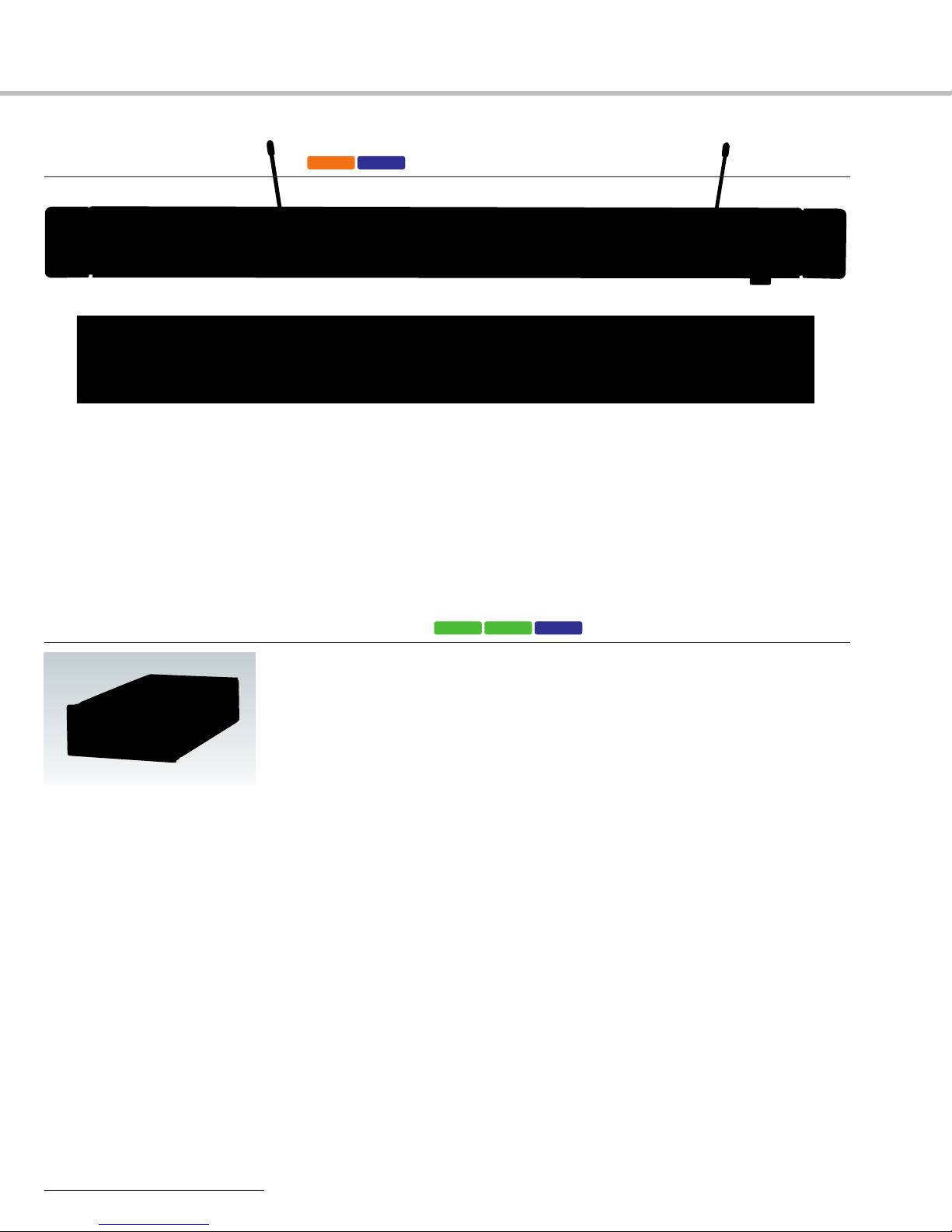
Tuners
MB-X6 Tuner Base Unit
• Accommodates up to six WRU-806A/806B for up to six
channels of simultaneous operation
• Addition of the WD-850 allows multi-channel operation
with even more channels
• Easy mechanism for attaching and detaching tuner
modules
• RF input attenuator switch (10 dB/0 dB)
U30-69 AU66
Front Panel: MB-X6 with six WRU-806A/806B tuner units installed
Rear Panel
• Balanced XLR output connector for each tuner and mix
output
• Selectable output level: -58 dBu (for MIC) or -20 dBu (for
LINE) at ±5 kHz deviation at 1 kHz modulation
• Auto channel search function automatically selects
unoccupied channels
• Supplied with passive antennas
• Modular, 1U high, 19-inch rack unit
WRU-806A/806B*UHF Synthesized Tuner Unit
• Plug-in diversity receiver module for MB-X6 tuner base unit
• Pre-programmed groups for interference free, multi-channel operation
• RF input status,audio output status,and battery alarm indications by both LED and
LCD to double check operating condition
• Space diversity reception for dependable RF reception
* Channel 30-33 and 42-45 operation is available when the WRU-806B (U30/32 or U42/44) is installed in the MB-X6.
U30/32 U42/44
AU66
12
Page 13

Distributors and Antenna
WD-850UHF Antenna Divider
• Provides diversity output for up to four receivers/tuner
base units
• Multi-channel operation by combination with the MB-8N
and WRU-8N or the MB-X6 and WRU-806A/806B
• Cascade output can be used for an additional antenna
divider or receiver/tuner base unit
* Original WD-850 supports Channel 62-69 operation. Channel 30-69 operation requires new WD-850 F model.
F(U30-69)AU
• Two pair of antenna input connectors for up to four
AN-820A antennas to expand the operating area of a
wireless microphone system
Front Panel
Rear Panel
AN-820AUHF Antenna
L(U30-45)AU66
• Built-in RF amplifier (10 dB gain)
•
Easy installation on a wall or on a microphone stand with the supplied stand adapter
• Used in pairs for diversity reception
• LED indication for installation check
•
External power supply provided from the MB-8N/806A/X6 or the WD-850 via a coaxial
cable
13
Page 14
Optional Accessories
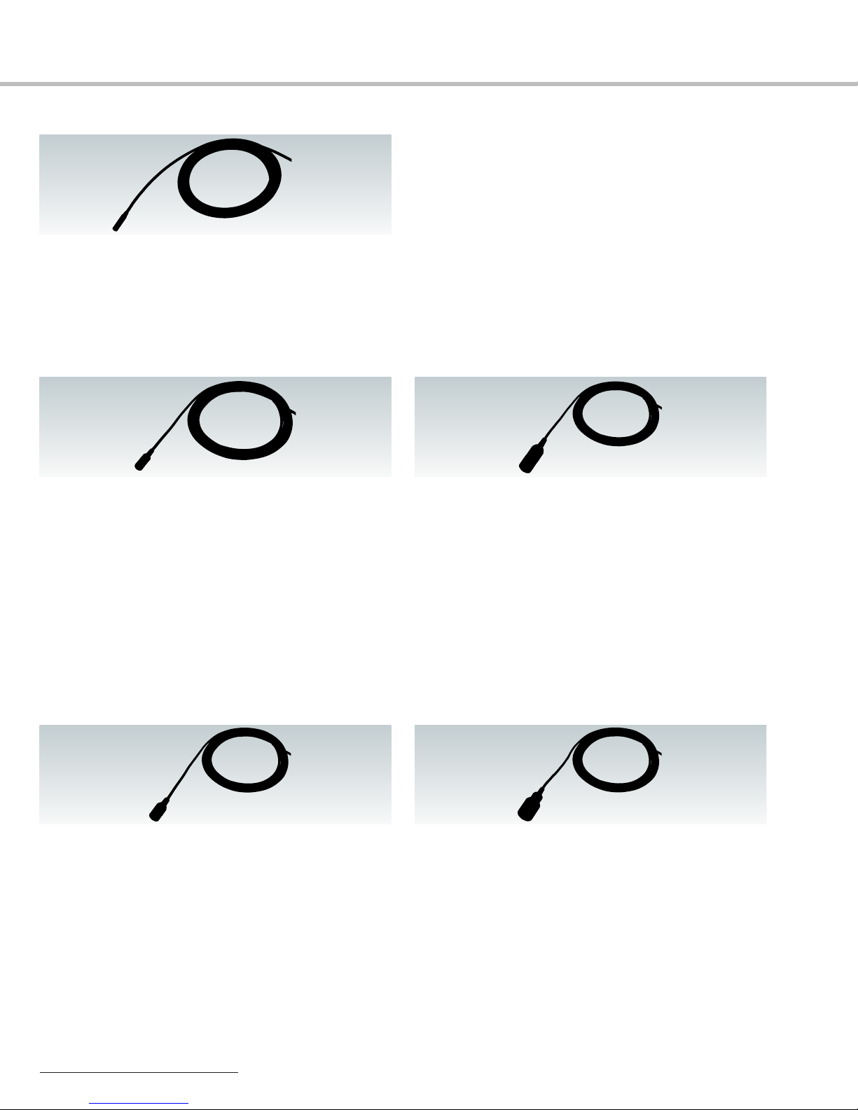
ECM-88 Series
Lavalier Microphone
• Ultra-miniature, omni-directional microphone
• Rectangular dual-diaphragm mechanism contributes to a
significant reduction in handling noise
• Water-resistant design
• Flat-and-wide frequency response: 20 Hz to 20 kHz
ECM-77 Series
Lavalier Microphone
• High performance, miniature microphone
• Omni-directional, electret condenser microphone
• Frequency response: 40 Hz to 20 kHz
• Sensitivity: -39.0 dB (11.2 mV) (0 dB = 1V/Pa, at 1 kHz)
• Microphone head: 1/4 inch (5.6 mm) dia. x 1/2 inch (12.5 mm),
approx. 0.05 oz (1.5 g)
•
Cable length: ECM-77BC: 3.9 feet (1.2 m), ECM-77BPT: 9.8 feet (3.0 m)
•
Two types available:
ECM-77BC: Black-colored model supplied with a Sony 4-pin
ECM-77BPT: Black-colored model supplied without a connector
connector (SMC9-4P), for use with the
WRT-8B/822A/822B
(pigtail), enabling users to choose connectors
according to their transmitter
• Sensitivity: -52 dB ±2 dB (in combination with optional DC-78)
-39 dB (12.6 mW)
• Signal-to-noise ratio: 68 dB or more (A-weighted, 1 kHz,1 Pa)
• Inherent nose: 26 dB SPL or less (A-weighted,1 kHz,1 Pa)
• Microphone head: 5/32 inch (3.5 mm) x 5/32 inch (3.5 mm) x
11/16 inch (16.8 mm),approx. 0.02 oz(0.6 g)
• Cable length: ECM-88BC: 3.9 feet (1.2 m), ECM-88BPT/88FPT:
8.2 feet (2.5 m)
• Three types available:
ECM-88BC: Black-colored model supplied with a Sony 4-pin
connector (SMC9-4P), for use with the
WRT-8B/822A/822B
ECM-88BPT: Black-colored model supplied without a connector
(pigtail), enabling users to choose connectors
according to their transmitter
ECM-88FPT: Beige-colored model supplied without a connector
(pigtail)
ECM-66BC
Lavalier Microphone
• Uni-directional,electret condenser microphone
• Resistant to howling by rejecting indirect sound
• Wide dynamic range (101 dB), and high maximum input-soundpressure level (130 dB SPL)
• Frequency: 70 Hz to 14 kHz
• Sensitivity: -36.5 dB (15 mV) (0 dB = 1 V/Pa, at 1 kHz)
• Low inherent-noise characteristics
• Microphone head: 7/16 inch (10.6 mm) dia. x 31/32 inch
(24.2 mm),approx. 0.25 oz (7 g)
• Cable length: 3.9 feet (1.2 m)
• Black-colored model supplied with a Sony 4-pin connector
(SMC9-4P), for use with the WRT-8B/822A/822B
ECM-44 Series
Lavalier Microphone
• Omni-directional, electret condenser microphone
• Superior sound quality
• Frequency response: 40 Hz to 15 kHz
• Sensitivity: -40 dB SPL (10 mV) (0 dB = 1V/Pa,at 1 kHz)
• Microphone head: 11/32 inch (8.5 mm) dia. x 19/32 inch
(14.5 mm),approx. 0.07 oz (2 g)
•
Cable length: ECM-44BC: 3.9 feet (1.2 m), ECM-44BPT: 9.8 feet (3.0 m)
• Two types available:
ECM-44BC: Black-colored model supplied with a Sony 4-pin
ECM-44BPT:
14
connector (SMC9-4P), for use with the
WRT-8B/822A/822B
Black-colored model supplied without a
connector (pigtail)
ECM-166BC
Lavalier Microphone
• Uni-directional,electret condenser microphone
• Resistant to howling by rejecting indirect sound
• Ideal for institutional uses and sound contracting applications
such as speeches,lectures and conferences
• Frequency response: 100 Hz to 10 kHz
• Sensitivity: -45 dB (5.6 mV) (0 dB = 1V/Pa, at 1 kHz)
• Microphone head: 1/2 inch (12.5 mm) dia. x 15/16 inch
(23.5 mm),approx. 0.12 oz (3.5 g)
• Cable length: 3.9 feet (1.2 m)
• Supplied with the Sony 4-pin (SMC9-4P) connector for use with
the WRT-8B/822A/822B
Page 15
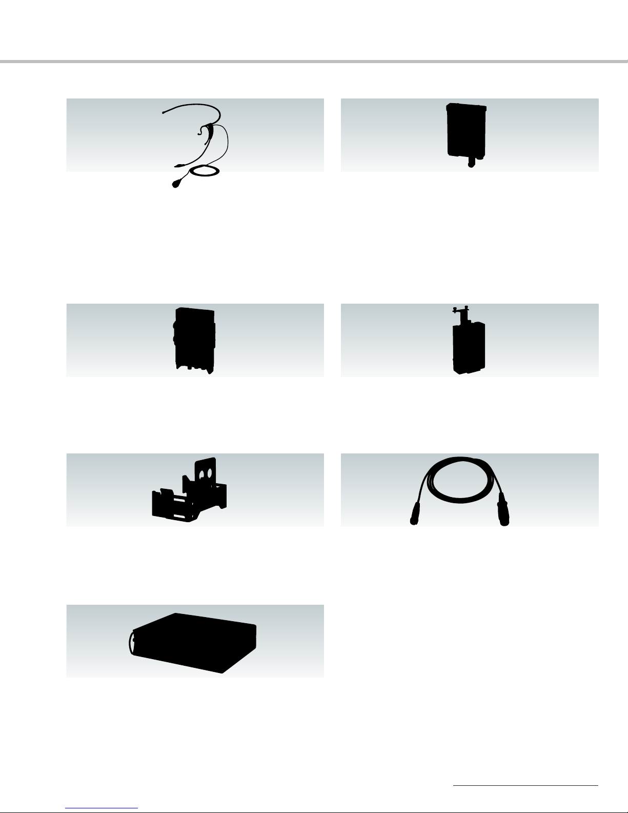
ECM-322BC
Headset Microphone
• Omni-directional, electret condenser microphone
• Ear-clip style design wearable on either the left or right ear
• Secure and comfortably fit with the adjustable soft-texture ear
hook and detachable headband
• Ideal for a variety of multimedia presentation applications
• Frequency response: 50 Hz to 18 kHz
• Sensitivity: -42 dB (7.94 mV) (0 dB = 1 V/Pa, at 1 kHz)
• Cable length: 3.9 feet (1.2 m)
• Supplied with the Sony 4-pin connector (SMC9-4P) for use with
the WRT-8B/822A/822B
BTA-801
Portable Tuner Mount Adapter
• Allows a WRR-855S portable tuner to be mounted on a Sony
professional camcorder
• External DC power input via the supplied 4-pin cable
DWA-01D
Digital Wireless Adapter
• Allows a WRR-855S portable tuner to be mounted on a Sony
profefssional camcorder
• External DC power input via the supplied 4-pin cable
• Headphone output for monitoring (stereo mini jack)
A-8278-057-B
Mounting Bracket
• For mounting any Sony portable tuner to Sony professional
camcorders which operate on Sony Lithium-Ion battery packs
DMX-P01
Digital Portable Mixer
• Portable, digital field-mixer designed for ENG/EFP application
• Compact and lightweight: 101/2 x 23/4 x 81/8 inches
(266 x 68 x 206 mm) and approx.4 lb 13 oz (2.2 kg)
• 24-bit A/D and D/A converters and internal 32-bit DSP for
excellent sound quality
• 4 microphone/line inputs with +48 V mic power (on/off)
CA-WR855
Camera Adapter
• Enables a WRR-855S portable tuner to be mounted on Sony
DSR-450WS/450WSP/400/400P DVCAM camcorders and
PDW-F355/F335 XDCAM®HD camcorders with direct
audio/power connection interfaces
EC-1.5CF
Microphone Cable
•
Fitted with an XLR-3-11 connector and SMC9-4P connector
• Allows a microphone with a 3-pin male XLR output connector to
be connected to WRT-8B/822A/822B bodypack transmitter
• Cable length: 4.9 feet (1.5 m)
• 2 channels of balanced analog output and AES/EBU digital
output (stereo) via XLR-type connectors
• Digital cascade input with phono connector
• Coaxial output connector for mix-bus output or S/PDIF digital
output
• Selectable sampling rate: 48 kHz or 96 kHz
• Full control of every parameter from the front panel using
physical and menu-driven controls
• Digital limiters on both inputs and outputs, and digital
compressors on outputs
• A scene memory recall feature to instantly recall up to ten
different user-defined parameter settings or factory default
settings
• Camera-audio return-level check via 12-pin connector
• Adjustable HPF with two user settings
• Operates on eight AA-size alkaline (LR6) batteries or external
DC 10 to 15 V power
15
Page 16

Frequency Lists
AU66 (AU type)
66-01 792.250
66-02 792.375
66-03 792.500
66-04 792.625
66-05 792.750
66-06 792.875
66-07 793.000
66-08 793.125
66-09 793.250
66-10 793.375
66-11 793.500
66-12 793.625
66-13 793.750
66-14 793.875
66-15 794.000
66-16 794.125
66-17 794.250
66-18 794.375
66-19 794.500
66-20 794.625
66-21 794.750
66-22 794.875
66-23 795.000
66-24 795.125
66-25 795.250
66-26 795.375
66-27 795.500
66-28 795.625
66-29 795.750
66-30 795.875
66-31 796.000
66-32 796.125
66-33 796.250
66-34 796.375
66-35 796.500
66-36 796.625
66-37 796.750
66-38 796.875
66-39 797.000
66-40 797.125
66-41 797.250
66-42 797.375
66-43 797.500
66-44 797.625
66-45 797.750
66-46 797.875
66-47 798.000
66-48 798.125
66-49 798.250
66-50 798.375
66-51 798.500
67-01 799.250
67-02 799.375
67-03 799.500
67-04 799.625
67-05 799.750
67-06 799.875
67-07 800.000
67-08 800.125
67-09 800.250
67-10 800.375
67-11 800.500
67-12 800.625
67-13 800.750
67-14 800.875
67-15 801.000
67-16 801.125
67-17 801.250
67-18 801.375
67-19 801.500
67-20 801.625
67-21 801.750
67-22 801.875
67-23 802.000
67-24 802.125
67-25 802.250
67-26 802.375
67-27 802.500
67-28 802.625
67-29 802.750
67-30 802.875
67-31 803.000
67-32 803.125
67-33 803.250
67-34 803.375
67-35 803.500
67-36 803.625
67-37 803.750
67-38 803.875
67-39 804.000
67-40 804.125
67-41 804.250
67-42 804.375
67-43 804.500
67-44 804.625
67-45 804.750
67-46 804.875
67-47 805.000
67-48 805.125
67-49 805.250
67-50 805.375
67-51 805.500
30-01 566.125
30-02 566.250
30-03 566.375
30-04 566.500
30-05 566.625
30-06 566.750
30-07 566.875
30-08 567.000
30-09 567.125
30-10 567.250
30-11 567.375
30-12 567.500
30-13 567.625
30-14 567.750
30-15 567.875
30-16 568.000
30-17 568.125
30-18 568.250
30-19 568.375
30-20 568.500
30-21 568.625
30-22 568.750
30-23 568.875
30-24 569.000
30-25 569.125
30-26 569.250
30-27 569.375
30-28 569.500
30-29 569.625
30-30 569.750
30-31 569.875
30-32 570.000
30-33 570.125
30-34 570.250
30-35 570.375
30-36 570.500
30-37 570.625
30-38 570.750
30-39 570.875
30-40 571.000
30-41 571.125
30-42 571.250
30-43 571.375
30-44 571.500
30-45 571.625
30-46 571.750
30-47 571.875
B30/32 (USA type)
31-01 572.125
31-02 572.250
31-03 572.375
31-04 572.500
31-05 572.625
31-06 572.750
31-07 572.875
31-08 573.000
31-09 573.125
31-10 573.250
31-11 573.375
31-12 573.500
31-13 573.625
31-14 573.750
31-15 573.875
31-16 574.000
31-17 574.125
31-18 574.250
31-19 574.375
31-20 574.500
31-21 574.625
31-22 574.750
31-23 574.875
31-24 575.000
31-25 575.125
31-26 575.250
31-27 575.375
31-28 575.500
31-29 575.625
31-30 575.750
31-31 575.875
31-32 576.000
31-33 576.125
31-34 576.250
31-35 576.375
31-36 576.500
31-37 576.625
31-38 576.750
31-39 576.875
31-40 577.000
31-41 577.125
31-42 577.250
31-43 577.375
31-44 577.500
31-45 577.625
31-46 577.750
31-47 577.875
32-01 578.125
32-02 578.250
32-03 578.375
32-04 578.500
32-05 578.625
32-06 578.750
32-07 578.875
32-08 579.000
32-09 579.125
32-10 579.250
32-11 579.375
32-12 579.500
32-13 579.625
32-14 579.750
32-15 579.875
32-16 580.000
32-17 580.125
32-18 580.250
32-19 580.375
32-20 580.500
32-21 580.625
32-22 580.750
32-23 580.875
32-24 581.000
32-25 581.125
32-26 581.250
32-27 581.375
32-28 581.500
32-29 581.625
32-30 581.750
32-31 581.875
32-32 582.000
32-33 582.125
32-34 582.250
32-35 582.375
32-36 582.500
32-37 582.625
32-38 582.750
32-39 582.875
32-40 583.000
32-41 583.125
32-42 583.250
32-43 583.375
32-44 583.500
32-45 583.625
32-46 583.750
32-47 583.875
33-01 584.125
33-02 584.250
33-03 584.375
33-04 584.500
33-05 584.625
33-06 584.750
33-07 584.875
33-08 585.000
33-09 585.125
33-10 585.250
33-11 585.375
33-12 585.500
33-13 585.625
33-14 585.750
33-15 585.875
33-16 586.000
33-17 586.125
33-18 586.250
33-19 586.375
33-20 586.500
33-21 586.625
33-22 586.750
33-23 586.875
33-24 587.000
33-25 587.125
33-26 587.250
33-27 587.375
33-28 587.500
33-29 587.625
33-30 587.750
33-31 587.875
33-32 588.000
33-33 588.125
33-34 588.250
33-35 588.375
33-36 588.500
33-37 588.625
33-38 588.750
33-39 588.875
33-40 589.000
33-41 589.125
33-42 589.250
33-43 589.375
33-44 589.500
33-45 589.625
33-46 589.750
33-47 589.875
42-01 638.125
42-02 638.250
42-03 638.375
42-04 638.500
42-05 638.625
42-06 638.750
42-07 638.875
42-08 639.000
42-09 639.125
42-10 639.250
42-11 639.375
42-12 639.500
42-13 639.625
42-14 639.750
42-15 639.875
42-16 640.000
42-17 640.125
42-18 640.250
42-19 640.375
42-20 640.500
42-21 640.625
42-22 640.750
42-23 640.875
42-24 641.000
42-25 641.125
42-26 641.250
42-27 641.375
42-28 641.500
42-29 641.625
42-30 641.750
42-31 641.875
42-32 642.000
42-33 642.125
42-34 642.250
42-35 642.375
42-36 642.500
42-37 642.625
42-38 642.750
42-39 642.875
42-40 643.000
42-41 643.125
42-42 643.250
42-43 643.375
42-44 643.500
42-45 643.625
42-46 643.750
42-47 643.875
B42/44 (USA type)
43-01 644.125
43-02 644.250
43-03 644.375
43-04 644.500
43-05 644.625
43-06 644.750
43-07 644.875
43-08 645.000
43-09 645.125
43-10 645.250
43-11 645.375
43-12 645.500
43-13 645.625
43-14 645.750
43-15 645.875
43-16 646.000
43-17 646.125
43-18 646.250
43-19 646.375
43-20 646.500
43-21 646.625
43-22 646.750
43-23 646.875
43-24 647.000
43-25 647.125
43-26 647.250
43-27 647.375
43-28 647.500
43-29 647.625
43-30 647.750
43-31 647.875
43-32 648.000
43-33 648.125
43-34 648.250
43-35 648.375
43-36 648.500
43-37 648.625
43-38 648.750
43-39 648.875
43-40 649.000
43-41 649.125
43-42 649.250
43-43 649.375
43-44 649.500
43-45 649.625
43-46 649.750
43-47 649.875
44-01 650.125
44-02 650.250
44-03 650.375
44-04 650.500
44-05 650.625
44-06 650.750
44-07 650.875
44-08 651.000
44-09 651.125
44-10 651.250
44-11 651.375
44-12 651.500
44-13 651.625
44-14 651.750
44-15 651.875
44-16 652.000
44-17 652.125
44-18 652.250
44-19 652.375
44-20 652.500
44-21 652.625
44-22 652.750
44-23 652.875
44-24 653.000
44-25 653.125
44-26 653.250
44-27 653.375
44-28 653.500
44-29 653.625
44-30 653.750
44-31 653.875
44-32 654.000
44-33 654.125
44-34 654.250
44-35 654.375
44-36 654.500
44-37 654.625
44-38 654.750
44-39 654.875
44-40 655.000
44-41 655.125
44-42 655.250
44-43 655.375
44-44 655.500
44-45 655.625
44-46 655.750
44-47 655.875
45-01 656.125
45-02 656.250
45-03 656.375
45-04 656.500
45-05 656.625
45-06 656.750
45-07 656.875
45-08 657.000
45-09 657.125
45-10 657.250
45-11 657.375
45-12 657.500
45-13 657.625
45-14 657.750
45-15 657.875
45-16 658.000
45-17 658.125
45-18 658.250
45-19 658.375
45-20 658.500
45-21 658.625
45-22 658.750
45-23 658.875
45-24 659.000
45-25 659.125
45-26 659.250
45-27 659.375
45-28 659.500
45-29 659.625
45-30 659.750
45-31 659.875
45-32 660.000
45-33 660.125
45-34 660.250
45-35 660.375
45-36 660.500
45-37 660.625
45-38 660.750
45-39 660.875
45-40 661.000
45-41 661.125
45-42 661.250
45-43 661.375
45-44 661.500
45-45 661.625
45-46 661.750
45-47 661.875
16
Page 17

Feature Comparisons
Handheld Microphones
WRT-847A WRT-807A
WRT-847B WRT-807B
UHF, PLL synthesized system ●●
Operating frequency band 24 MHz band (WRT-847B,USA type) 24 MHz band (WRT-807B,USA type)
Tone signal ●●
Compander system (compressor) ●●
Microphone capsule Dynamic,uni-directional
Audio-attenuator levels -12 dB to +9 dB (in 3 dB steps) 0 dB to 21 dB (in 3 dB steps)
Antenna
RF power output 50 mW or 10 mW 10 mW
LCD panel Channel number, Channel number,
LED indicators ——
Transmission of battery status ●●
Battery life Approx.8 hours Approx. 5 hours
Channel setting back-up ●●
Supplied accessories Microphone holder (1), Microphone holder (1),
14 MHz band (WRT-847A,AU type) 14 MHz band (WRT-807A, AU type)
Dynamic, omni-directional (with optional CU-F117)
Electret condenser, uni-directional (with optional CU-E700/E672)
1/4 wavelength whip antenna
Frequency in MHz, Frequency in MHz,
Audio input status, Audio input status,
RF-output level setting (Low or High), RF output status,
RF output status, Attenuator level,
Compander time constant, Battery reserve,
Attenuator level, A
Battery reserve,
Accumulated operating time
Stand adapter (1), Metal-screw stand adapter (1),
Channel color seal (1), Operating instructions (1)
Soft case (1),
Operating instructions (1)
(with optional CU-F780/G780)
Dynamic, uni-directional
1/4 wavelength whip antenna
ccumulated operating time
Bodypack/Plug-on Transmitters
WRT-8B WRT-822A WRT-8P
UHF, PLL synthesized system ●●●
Operating frequency band 24 MHz band (USA type) 24 MHz band (WRT-822B,USA type) 24 MHz band (USA type)
Tone signal ●● ●
Compander system (compressor) ●● ●
Audio-attenuator levels 0 dB to 40 dB, continuous 0 dB to 21 dB (in 3 dB steps) 0 dB to 25 dB,continuous
Antenna
RF power output 50 mW or 10 mW 10 mW with WRT-822A 250 mW or 50 mW
LCD panel Channel number, Channel number, Channel number,
LED indicators Audio input level (peak level) —
Transmission of battery status ●● ●
Audio input connectors Sony 4-pin (SMC9-4S) Sony 4-pin (SMC9-4S) XLR type 3-pin
Battery life* Approx. 13 hours at 10 mW output Approx. 8 hours with WRT-822A Approx. 2.5 hours at 250 mW output
Channel setting back-up ●●●
Supplied accessories Soft case (1), Leatherette case (1), Soft case (1),
14 MHz band (AU type) 14 MHz band (WRT-822A,AU type)
1/4 wavelength whip antenna (removable)
Frequency in MHz, Frequency in MHz, Frequency in MHz,
Audio input status, Audio input status, Audio input status,
RF output level setting RF output status, Audio input status (MIC/LINE),
(Low or High), Attenuator level, RF output level setting (Low or High),
RF output status, Battery reserve, RF output status,
Battery reserve, A
A
ccumulated operating time
Approx. 6 hours at 50 mW output Approx.6 hours with WRT-822B Approx.4 hours at 50 mW output
Spare battery case (1), Operating instructions (1) Operating instructions (1)
Microphone cable (SMC9-4P to XLR 3-pin) (1),
Operating instructions (1)
WRT-822B
1/4 wavelength whip antenna Integrated type
20 mW with WRT-822B
ccumulated operating time
Battery reserve,
+48 V power status
Audio input level (reference level or peak level)
+48 V power supply
*When not supplying power to the microphone
17
Page 18

Feature Comparisons
Portable Tuners
WRR-862A WRR-855S WRR-861A
WRR-862B WRR-861B
UHF, PLL synthesized system ●●●
Operating frequency band 24 MHz band (WRR-862B, USA type) 24 MHz band (USA type) 24 MHz band (WRU-861B, USA type)
Space diversity reception system ●●●
Pre-programmed frequency groups ●●●
Advanced filtering (SAW filters) ●●●
Tone squelch circuitry ●●●
Compander system (expander) ●●●
RF squelch levels 5 dBµ, 10 dBµ,15 dBµ or OFF 10 dBµ or OFF 5 dBµ, 10 dBµ,15 dBµ or OFF
LCD panel Channel number, Channel number, Channel number,
LED indicators RF input level, RF input level, RF input level,
Remote battery alarm of transmitters
Audio output connectors Sony 4-pin (SMC9-4S) D-sub 15-pin Sony 4-pin (SMC9-4S)
Battery life Approx.5 hours —* Approx. 8 hours
Channel setting back-up ●●●
Supplied accessories Attachment case (1), Antennas (1 pair), Attachment case (1),
14 MHz band (WRR-862A, AU type) 14 MHz band (AU type) 14 MHz band (WRU-861A, AU type)
Frequency in MHz, RF input level, Frequency in MHz,
RF input level, Audio output status RF input level,
Audio output status, Audio output status,
Tuner battery reserve, Tuner battery reserve,
Accumulated operating time Accumulated operating time
Diversity reception status, Audio output status, Diversity reception status,
Transmitter battery alarm
● ●●
Mounting plate for use with optional Operating instructions (1) Mounting plate for use with optional
A-8278-057-B Mounting bracket (1), A-8278-057-B Mounting bracket (1),
Antennas (1 pair), Antennas (1 pair),
Output cable (SMC9-4S to XLR 3-pin) (2), Output cable (SMC9-4S to XLR 3-pin) (1),
DC cable (1), DC cable (1),
Operating instructions (1) Operating instructions (1)
Transmitter battery alarm
*The WRR-855S receives power from a camcorder via the D-sub 15-pin connector.
Transmitter battery alarm
Tuners
MB-8N with MB-X6 with
WRU-8N WRU-806A/WRU-806B
UHF, PLL synthesized system ●●
Operating frequency band 24 MHz band (USA type) 24 MHz band (WRU-806B, USA type)
Space diversity reception system ●●
Pre-programmed frequency groups ●●
Advanced filtering (SAW filters) ●●
Tone squelch circuitry ●●
Compander system (expander) ●●
RF squelch levels 10 dBµ, 20 dBµ,30 dBµ or OFF 30 dBµ
LCD panel MB-8N: Menus for parameter setup WRU-806A/806B: Channel number,
LED indicators WRU-8N: Diversity reception status, WRU-806A/806B: RF input status,
Remote battery alarm of transmitters ●●
Audio output connectors XLR 3-pin type (main) and D-sub 15-pin, female (sub) XLR 3-pin type
Computer-based control ● —
Channel setting back-up ●●
Supplied accessories MB-8N: AC power cord (1), MB-X6: AC power cord (1),
14 MHz band (AU type) 14 MHz band (WRU-806A, AU type)
WRU-8N: Channel number, Frequency in MHz,
Frequency in MHz, RF input level,
RF input level, Audio output status,
Audio output status, Transmitter battery reserve
Audio output status, Audio output status,
Transmitter battery alarm Transmitter battery alarm
CD-ROM containing operating instructions and Antennas (1 pair),
MB-8N supplied software (1) Operating instructions (1)
WRU-8N: — WRU-806A/806B: —
18
Page 19

Specifications
Handheld Microphones
WRT-847A/847B WRT-807A/807B
Carrier frequency range 566 MHz to 590 MHz (U30/32) 566 MHz to 590 MHz (U30/32)
Oscillator Crystal controlled PLL synthesizer Crystal controlled PLL synthesizer
Type of emission F3E F3E
RF power output 10 mW/50 mW selectable (50 Ω load) 10 mW (50 Ω load)
Antenna 1/4 wave length wire antenna 1/4 wave length wire antenna
Reference deviation ±5 kHz (94 dB SPL,1 kHz) ±5 kHz (94 dB SPL, 1 kHz)
Frequency response 50 Hz to 18 kHz (typical) 50 Hz to 15 kHz (typical)
Signal-to-noise ratio 60 dB or more 60 dB or more
Audio attenuator -12 dB to +9 dB variable in 3 dB steps 0 to 21 dB,variable in 3 dB steps
adjustment range (pad)
Max.input sound pressure level 142 dB SPL (with CU-F780/G780/E700/F117 at 151 dB SPL (with 21 dB attenuator)
Microphone capsule Interchangeable (Optional) Dynamic
Directivity — Uni-directional
Operating voltage DC 3.0 V (two LR6 AA-size alkaline batteries) DC 1.5 V (one LR6 AA-size alkaline battery)
Battery life (at 25 °C (77 °F),with
Sony LR6 AA-size alkaline batteries)
Dimensions ø 11/2 x 6 inches (ø 37 x 150 mm) ø 21/8 x 93/8 inches (ø 51 x 238 mm)
Weight Approx.6.7 oz (190 g) including batteries Approx.15.5 oz (440 g) including battery
Supplied accessories Microphone holder (1), Stand adapter (1), Microphone holder (1),
Channel color seal (1), Softcase (1), Metal-screw stand adapter (1),
638 MHz to 662 MHz (U42/44) 638 MHz to 662 MHz (U42/44)
792 MHz to 806 MHz (AU66) 792 MHz to 806 MHz (AU66)
(A-weighted,at reference deviation) (A-weighted, at reference deviation)
audio gain -12 dB)
120 dB SPL (with CU-E672)
Approx. 8 hours Approx. 5 hours
Operating instructions (1) Operating instructions (1)
Bodypack/Plug-on Transmitters
WRT-8B WRT-822A/822B WRT-8P
Carrier frequency range 566 MHz to 590 MHz (U30/32) 566 MHz to 590 MHz (U30/32) 566 MHz to 590 MHz (U30/32)
Oscillator Crystal controlled PLL synthesizer Crystal controlled PLL synthesizer Crystal controlled PLL synthesizer
Type of emission F3E F3E F3E
RF power output 10 mW or 50 mW (e.r.p.) selectable 10 mW (AU-type) (50 Ω load) 250 mW or 50 mW selectable
Antenna 1/4 wave length wire antenna 1/4 wave length wire antenna Integrated type
Reference deviation ±5 kHz (-60 dBV, 1 kHz input,MIC position) ±5 kHz (-60 dBV, 1 kHz input) ±10 kHz (-60 dBV, 1 kHz input,MIC position)
Frequency response 40 Hz to 20 kHz (typical) 70 Hz to 15 kHz (typical) 50 Hz to 18 kHz (typical)
Signal-to-noise ratio 60 dB or more 60 dB 60 dB or more
Audio attenuator 0 to 40 dB,continuous 0 to 21 dB, variable in 3 dB step 0 dB to 25 dB, continuous
adjustment range (pad)
Max.input level -2 dBV (1 kHz input, MIC position) -3 dBV (with 21 dB attenuator) -20 dBV (1 kHz input, MIC position, ATT=0 dB)
Input connectors Sony 4-pin (SMC9-4S) (1) Sony 4-pin (SMC9-4S) (1) XLR type 3-pin, female
Operating voltage DC 3.0 V DC 3.0 V DC 9.0 V
Battery life (at 77 °F (25 °C),with
Sony LR6 AA-size alkaline batteries)*
Dimensions (W x H x D) 2
Weight Approx.4.9 oz (140 g) including batteries Approx.5.1 oz (145 g) including batteries Approx. 8.1 oz (230 g) including battery
Supplied accessories Soft case (1) , Leatherette case (1), Soft case (1),
638 MHz to 662 MHz (U42/44) 638 MHz to 662 MHz (U42/44) 638 MHz to 662 MHz (U42/44)
792 MHz to 806 MHz (AU66) 792 MHz to 806 MHz (AU66)
20 mW (USA-type) (50 Ω load)
(SMA-J type connector)
±5 kHz (-20 dBu,1 kHz input, LINE position) ±10 kHz (-18 dBu, 1 kHz input,LINE position)
(A-weighted,at reference deviation) (A-weighted, at reference deviation) (A-weighted,at reference deviation)
+38 dBu (1 kHz input,LINE position) +22 dBu (1 kHz input,LINE position, ATT=0 dB)
(two LR6 AA-size alkaline batteries) (two LR6 AA-size alkaline batteries) (one 6LR61 alkaline battery)
Approx. 6 hours at 50 mW output Approx. 8 hours (AU-type) Approx.2.5 hours at 250 mW output
Approx. 13 hours at 10 mW output Approx.6 hours (USA-type) Approx. 4 hours at 50 mW output
1
/2 x 33/8 x11/16 inches 21/2 x 41/8 x11/16 inches 13/4 x 41/4 x 13/4 inches
(63 x 83 x 17 mm) (63 x 103 x 17 mm) (44 x 106 x 44 mm)
Spare battery case (1), Operating instructions (1) Operating instructions (1)
Microphone cable (1),
Operating instructions (1)
*When not supplying power to the microphone
19
Page 20

Specifications
Portable Tuners
WRR-862A/862B WRR-855S WRR-861A/861B
Receiving channels 2 channels 1 channel 1 channel
Receiving frequency range 2 frequencies within 566 MHz to 590 MHz (U30/32) 566 MHz to 590 MHz (U30/32) 566 MHz to 590 MHz (U30/32)
Local oscillators 1st: PLL synthesizer, 1st: PLL synthesizer, 1st: PLL synthesizer,
De-emphasis 50 µs 50 µs 50 µs
Reference deviation ±5 kHz deviation at 1 kHz modulation ±5 kHz deviation at 1 kHz modulation ±5 kHz deviation at 1 kHz modulation
Selectivity 60 dB or more at ±250 kHz 60 dB or more at ±250 kHz 60 dB or more at ±250 kHz
Spurious rejection 70 dB or more 80 dB or more 70 dB or more
Frequency range 40 Hz to 18 kHz (typical) 40 Hz to 18 kHz (typical) 40 Hz to 18 kHz (typical)
Signal-to-noise ratio 60 dB or more (65 dB typical) at 60 dBµ RF input 60 dB or more at 60 dBµ RF input 60 dB or more (65 dB typical) at 60 dBµ RF input
RF muting (squelch) level 5 dBµ,10 dBµ,15 dBµ or OFF 10 dBµ or OFF 5 dBµ, 10 dBµ,15 dBµ or OFF
Audio output level -58 dBm at reference deviation -40 dBu at reference deviation -58 dBm at reference deviation
Audio output connector SMC9-4S (Sony 4-pin) (2),balanced D-sub 15-pin (1),unbalanced SMC9-4S (Sony 4-pin) (1),balanced
Antenna connector BNC-R type (2), 50 Ω (nominal) BNC-R type (2),50 Ω (nominal) BNC-R type (2),50 Ω (nominal)
Monitor output connector 3.5 mm dia.mini jack, 1, 5 mW (1) —
Operating voltage Batteries: DC 6 V External: DC 7 V Batteries: DC 6 V
Battery life (at 25 °C (77 °F),with
Sony LR6 AA-size alkaline batteries)
Current (power) consumption Batteries: approx.230 mA at DC 6 V 200 mA or less at external DC 7 V Batteries: approx.140 mA at DC 6 V
Dimensions (W x H x D) 3
Weight Approx.14.1 oz (400 g) Approx.10.0 oz (280 g) Approx. 14.1 oz (400 g)
Supplied accessories Attachment case (1), Antennas (1 pair), Attachment case (1),
2 frequencies within 638 MHz to 662 MHz (U42/44) 638 MHz to 662 MHz (U42/44) 638 MHz to 662 MHz (U42/44)
2 frequencies within 792 MHz to 806 MHz (AU66) 792 MHz to 806 MHz (AU66) 792 MHz to 806 MHz (AU66)
2nd: Crystal oscillator 2nd: PLL synthesizer 2nd: Crystal oscillator
(Maximum deviation: ±40 kHz deviation (Maximum deviation: ±40 kHz deviation (Maximum deviation: ±40 kHz deviation
at 1 kHz modulation) at 1 kHz modulation) at 1 kHz modulation)
at reference deviation,A-weighted at reference deviation,A-weighted at reference deviation, A-weighted
Tuner 1/2/Mixed selectable
(four LR6 AA-size alkaline batteries) (four LR6 AA-size alkaline batteries)
External: DC 12 V External: DC 12 V
Approx. 5 hours — Approx. 8 hours
External: approx. 135 mA at DC 12 V External: approx. 85 mA at DC 12 V
5
/8 x 43/4 x 13/16 inches 31/2 x 43/4 x 11/4 inches 35/8 x 43/4 x 13/16 inches
(89.0 x 120.0 x 29.5 mm) (88.0 x 119.0 x 31.3 mm) (89.0 x 120.0 x 29.5 mm)
including batteries including batteries
Mounting plate for use with optional Operating instructions (1) Mounting plate for use with optional
A-8278-057-B mounting bracket (1), A-8278-057-B mounting bracket (1),
Antennas (1 pair),Output cables (2), Antennas (1 pair),output cable (1),
DC cable (1), DC cable (1),
Operating instructions (1) Operating instructions (1)
3.5 mm dia.stereo mini jack
, 1, 5 mW (1)
Tuners
WRU-8N WRU-806A/806B
Receiving channels 1 channel 1 channel
Receiving frequency range 566 MHz to 590 MHz (U30/32) 566 MHz to 590 MHz (U30/32)
Local oscillators PLL synthesizer 1st: PLL synthesizer,
De-emphasis 50 µs 50 µs
Reference deviation ±5 kHz deviation at 1 kHz modulation ±5 kHz deviation at 1 kHz modulation
Selectivity 60 dB or more at ±250 kHz 60 dB or more at ±250 kHz
Frequency range 40 Hz to 20 kHz (typical) 70 Hz to 18 kHz (typical)
Signal-to-noise ratio 60 dB or more (65 dB typical) at 60 dBµ RF input 60 dB or more at 60 dBµ RF input at
RF muting (squelch) level 10 dBµ, 20 dBµ,30 dBµ or off 30 dBµ
Operating voltage DC 5 V (supplied from MB-8N) DC 9 V (supplied from MB-X6)
Current (power) consumption 260 mA or less 225 mA or less
Dimensions (W x H x D) 2
Weight Approx.5.8 oz (165 g) Approx. 5.7 oz (160 g)
Supplied accessories — Operating instructions (1)
638 MHz to 662 MHz (U42/44) 638 MHz to 662 MHz (U42/44)
792 MHz to 806 MHz (AU66) 792 MHz to 806 MHz (AU66)
2nd: Crystal oscillator
(Maximum deviation: ±40 kHz deviation at (Maximum deviation: ±40 kHz deviation at
1 kHz modulation) 1 kHz modulation)
at reference deviation,A-weighted reference deviation,deviation,A-weighted
1
/4 x 11/4 x 57/8 inches 21/4 x 11/16 x 47/8 inches
(56.0 x 30.7 x 149.0 mm) (57 x 26 x 122 mm)
20
Page 21
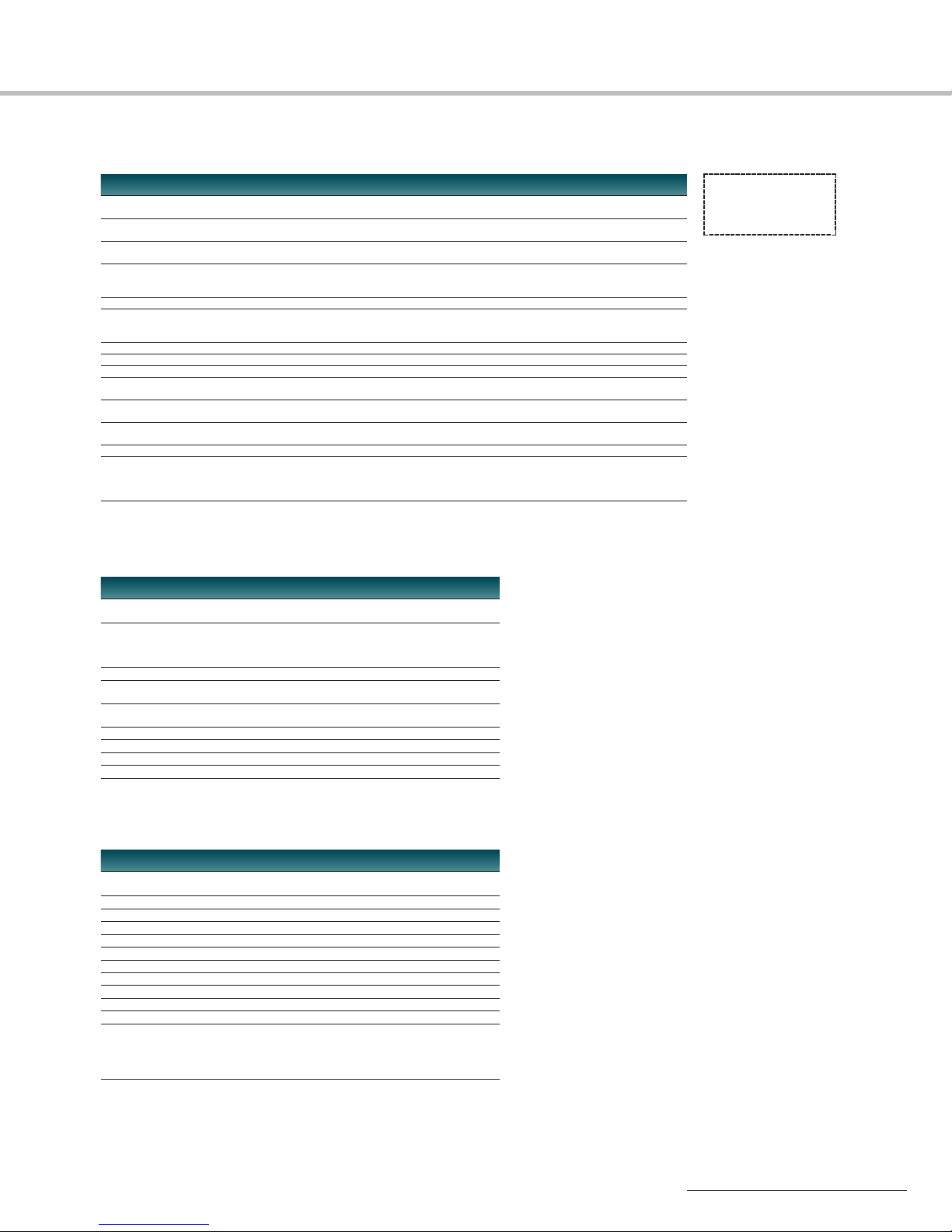
Tuner Base Units
Receiving channels
Receiving frequency range
Audio output level -20 dBm (LINE)/-58 dBm (MIC) at reference -20 dBu (LINE)/-58 dBu (MIC) at reference
Audio output connector XLR-3-32 type (4),balanced XLR-3-32 (7),balanced
Antenna attenuator level 0 dB, 5 dB,10 dB or 15 dB 0 dB or 10 dB
Antenna connector Inputs: BNC-R type (x 2),50 Ω (nominal) Inputs: BNC-R type (2),50 Ω (nominal)
Monitor output level 5 mW or more (24 to 45 Ω load) —
Monitor output connector 6.3 mm dia,stereo mini jack (1) —
Network connector RJ-45 (1), 10BASE-T —
Operating voltage AC 120 V,60 Hz (USA-type) AC 120V, 60 Hz (USA-type)
Current (power) consumption 50 W when accommodating 30 W when accommodating
Dimensions (W x H x D) 19 x 1
Weight Approx.8 lb 6 oz (3.7 kg) Approx.12 lb 2 oz (5.5 kg)
Supplied accessories AC power cord (1), AC power cord (1),
*Original MB-8N supports Channel 62-69 operation. Channel 30-69 operation requires new MB-8N F model.
MB-8N* MB-X6
4 channels when accommodating 6 channels when accommodating
4 WRU-8N tuner modules
566 MHz to 806 MHz (USA type) 566 MHz to 806 MHz (USA type)
758 MHz to 862 MHz (AU type) 758 MHz to 862 MHz (AU type)
deviation deviation
D-sub 15-pin (1) for sub output, female,
unbalanced
Outputs (for cascade connection):
BNC-R type (2), 50 Ω (nominal)
AC 100 to 240V, 50/60 Hz (AU-type) AC 230 V, 50/60 Hz (AU-type)
fourWRU-8N tuner modules six WRU-806A/806B tuner modules
3
/4 x 117/8 inches 19 x 13/4 x 11 1/4 inches
(482 x 44 x 300 mm) (482 x 44 x 285 mm)
Antennas (1 pair), Antennas (1 pair),
CD-ROM (contains operating
MB-8N supplied
software) (1)
instructions and
6 WRU-806A/806B tuner modules
Operating instructions (1)
Antenna Dividers
WD-850*
Frequency range 566 MHz to 806 MHz (USA type)
Channel distribution Inputs: 2 pairs
758 MHz to 862 MHz (AU type)
Outputs: 4 pairs
0 dB SPL = 20µ Pa
0 dBV = 1 Vrms
1 dBu = 0.775 Vrms
1 dBµ = 1µV
EMF
Input/output impedance 50 Ω
Cascade output 1 pair
Power supply for antenna booster DC 9 V/OFF switchable
(supplied from antenna input connectors)
Power consumption 16 W
Dimensions (W x H x D) 19 x 13/4 x 117/8 inches (482 x 44 x 300 mm)
Weight Approx.10 lb 2 oz (4.6 kg)
Supplied accessories 50 Ω BNC terminators (6)
*Original WD-850 supports Channel 62-69 operation.
Channel 30-69 operation requires new WD-850 F model.
Antenna
AN-820A
Frequency range 566 MHz to 662 MHz (USA type,L model)
Antenna gain Approx. 10 dB
Output impedance 50 Ω
Voltage standing-wave ratio Less than 3
Noise figure Less than 6 dB
Third intermodulation More than 60 dB (at 95 dBÉ output)
Output connector BNC-R type
Supply voltage DC 9 V
Current consumption Less than 35 mA
Dimensions (W x H x D) 27/8 x 45/8 x 51/4 inches (70 x 117 x 132 mm)
Weight Approx.9 oz (250 g)
Supplied accessories Attachment A (1),
758 MHz to 862 MHz (AU type)
Attachment B (1),
Microphone stand screw (1),
Microphone stand screw adapter (PF 1/2 to NS 5/8) (1),
Fixing screws (1 set)
21
Page 22

Specifications
Appendix
Multi-channel Simultaneous Operations
Tuner and Camcorder Combinations
Attaching to Camcorders
22
Page 23
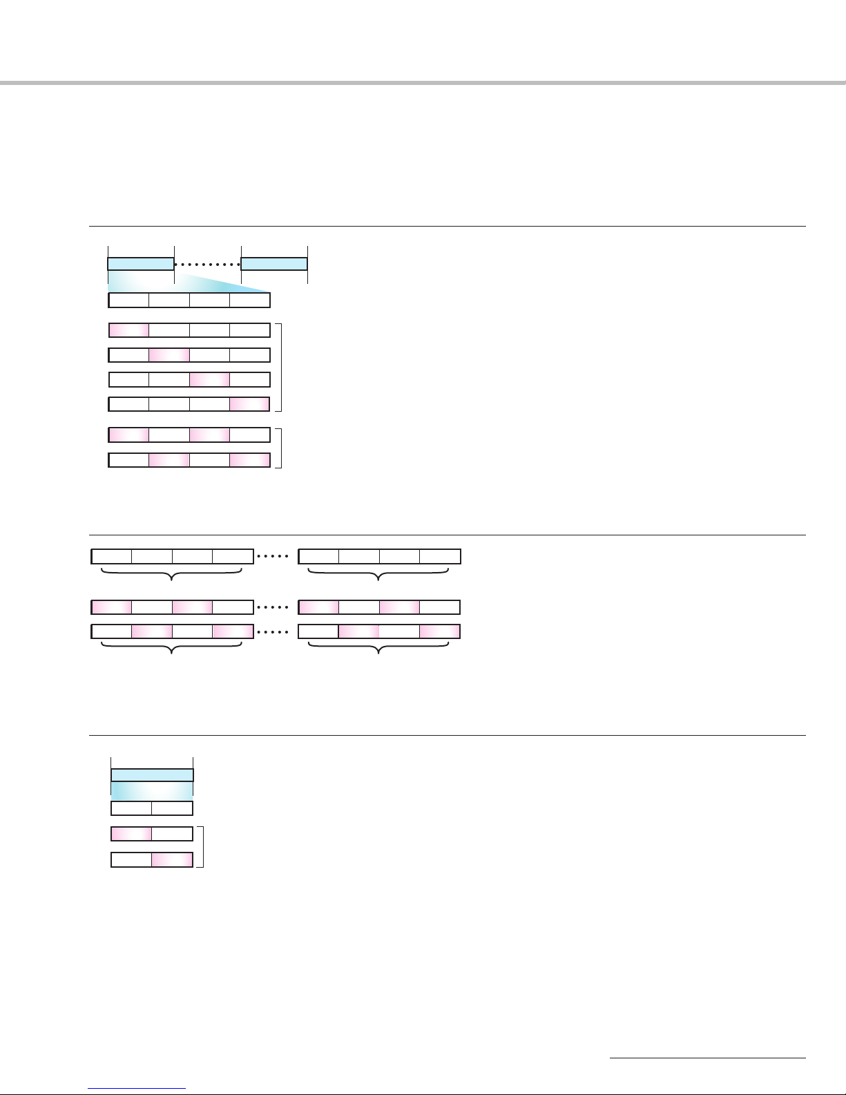
Multi-channel Simultaneous Operations
B30/32
or
or
or
TV 30 ch TV 31 ch TV 32 ch TV 33 ch
TV TV 31 ch TV 33 chTV 32 ch
TV TV 33 chTV 32 ch
TV 32 ch
TV 32 ch
TV 30 ch
TV 30 ch
TV 30 ch
TV 30 ch
TV 31 ch
TV 31 ch
TV TV33 ch
TV
TV
or
TV TV 31 ch TV TV 33 ch
TV
B42/44
566 MHz 662 MHz590 MHz 638 MHz
When all four TV channeles are available,
up to 16-channel simultaneous operation is possible.
When three of four TV channeles are available,
up to 14-channel simultaneous operation is possible.
When either the even or the odd TV channeles are
available, up to 11-channel simultaneous operation
is possible.
(24 MHz band)(24 MHz band)
or
TV 66 ch TV 67 ch
TV
TV
TV 67 ch
TV 66 ch
A66
792 MHz 806 MHz
When both two TV channeles (66 and 67) are available,
up to 12-channel simultaneous operation is available.
When one of the two TV channeles is available,
up to 9-channel simultaneous operation is possible.
(14 MHz band)
or
16-channel
11-channel
TV 30 ch TV 31 ch TV 32 ch TV 33 ch
TV 30 ch TV 32 ch
TV TV 31 ch TV
TV TV
TV 33 ch
11-channel
TV 42 ch TV 44 ch
TV TV
TV TV 43 ch TV TV 45 ch
16-channel
TV 42 ch TV 43 ch TV 44 ch TV 45 ch
When all eight TV channels are available;
up to 32-channel simultaneous operation is possible.
When either all even or all odd TV channels are available;
up to 22-channel simultaneous operation is possible.
The Sony wireless microphone system allows a wide variety of multi-channel systems
to be flexibly configured to meet individual requirements.
The number of channels that can be simultaneously operated using
One Version of B-series (USA-type) Products is as follows;
The number of channels that can be simultaneously operated using
the B30/32 and B42/44 Combination is as follows;
The number of channels that can be simultaneously operated using
the AU Products is as follows;
23
Page 24
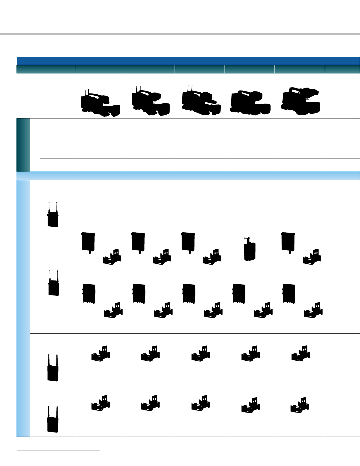
Tuner and Camcorder Combinations
HDCAM
HDW-F900R
HDW-790/790P
HDW-650F/650P
HDW-730S
HD
XDCAM HD422 XDCAM HD
PDW-700
PDW-F355
PDW-F335
HDV
HVR-S270
for Audio
Camcorder Interfaces
Built-in
Wireless Slot
DC Output
Audio Input
Mic Input
WRR-855S
(1ch)
Slot-in
Rear Mount
Yes Yes
Yes
XLR 3-pin (x2)
XLR 5-pin (x1)
No mounting
accessories needed
BTA-801
Wireless
Adapter
A-8278-057-B
Mount
Bracket
Yes
XLR 3-pin (x2)
XLR 3-pin (x1)
No mounting
accessories needed
BTA-801
Wireless
Adapter
A-8278-057-B
Mount
Bracket
Yes
Yes
XLR 3-pin (x2)
XLR 5-pin (x1)
Required Components
No mounting
accessories needed
BTA-801
Wireless
Adapter
A-8278-057-B
Mount
Bracket
No
Yes
XLR 3-pin (x2)
XLR 5-pin (x1)
—
*
CA-WR855
Mount Adapter
XLR 3-pin (x2)
XLR 3-pin (x1)
BTA-801
Wireless
Adapter
No
Yes
—
A-8278-057-B
Mount
Bracket
DWA-01D
Digital Wireless
Adapter
A-8278-057-B
Mount
Bracket
Applicable Wireless Tuners
WRR-861A/861B
(1ch)
Rear Mount
A-8278-057-B
Mount Bracket
WRR-862A/862B
(2ch)
Rear Mount
A-8278-057-B
Mount Bracket
24
DWA-01D
Digital Wireless
Adapter
A-8278-057-B
Mount Bracket
A-8278-057-B
Mount Bracket
A-8278-057-B
Mount
Bracket
DWA-01D
Digital Wireless
Adapter
A-8278-057-B
Mount Bracket
A-8278-057-B
Mount Bracket
A-8278-057-B
Mount
Bracket
DWA-01D
Digital Wireless
Adapter
A-8278-057-B
Mount Bracket
A-8278-057-B
Mount Bracket
A-8278-057-B
Mount
Bracket
DWA-01D
Digital Wireless
Adapter
A-8278-057-B
Mount Bracket
A-8278-057-B
Mount Bracket
A-8278-057-B
Mount
Bracket
Page 25
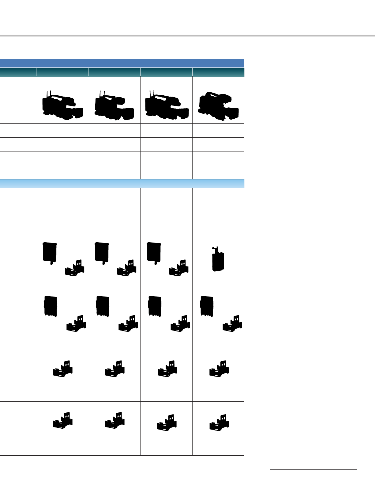
Digital Betacam
DVW-970/970P
XDCAM SD
PDW-530/530P
PDW-510/510P
SD
MPEG IMX DVCAM
MSW-970/970P
DSR-400/400P
DSR-450WS/450WSP
Yes
Yes
XLR 3-pin (x2)
XLR 3-pin (x1)
No mounting
accessories needed
BTA-801
Wireless
Adapter
A-8278-057-B
Mount
Bracket
Yes
Yes
XLR 3-pin (x2)
XLR 3-pin (x1)
No mounting
accessories needed
BTA-801
Wireless
Adapter
A-8278-057-B
Mount
Bracket
Yes
Yes
XLR 3-pin (x2)
XLR 3-pin (x1)
No mounting
accessories needed
BTA-801
Wireless
Adapter
A-8278-057-B
Mount
Bracket
No
Yes
XLR 3-pin (x2)
XLR 3-pin (x1)
—
*
CA-WR855
Mount Adapter
DWA-01D
Digital Wireless
Adapter
A-8278-057-B
Mount
Bracket
A-8278-057-B
Mount Bracket
A-8278-057-B
Mount Bracket
* When using a battery from a third-party manufacturer to operate the camcorder, the BTA-801 or
DWA-01D adapter is recommended instead of the CA-WR855.
DWA-01D
Digital Wireless
Adapter
A-8278-057-B
Mount Bracket
A-8278-057-B
Mount Bracket
A-8278-057-B
Mount
Bracket
DWA-01D
Digital Wireless
Adapter
A-8278-057-B
Mount Bracket
A-8278-057-B
Mount Bracket
A-8278-057-B
Mount
Bracket
DWA-01D
DigitalWireless
Adapter
A-8278-057-B
Mount Bracket
A-8278-057-B
Mount Bracket
A-8278-057-B
Mount
Bracket
25
Page 26
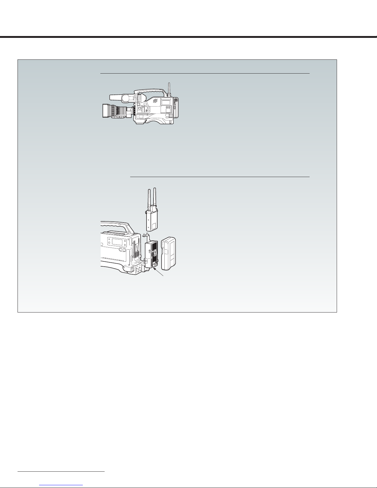
Attaching to Camcorders
Required components
• WRR-855S Portable tuner x 1
Slot-in Configuration
Camera Adapter Configuration
Required components
• WRR-855S Portable tuner x 1
• CA-WR855 Camera adapter x 1
CA-WR855
26
Page 27
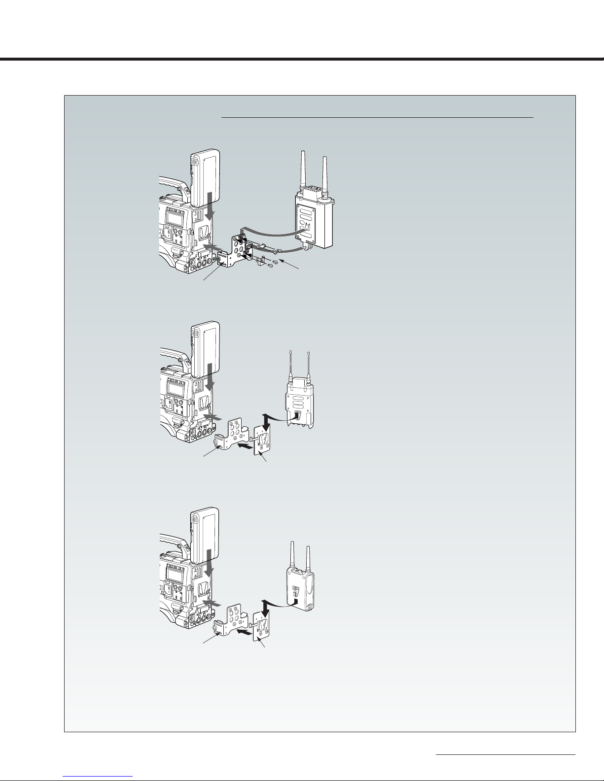
Required components
• WRR-855S Portable tuner x 1
• BTA-801 Wireless adapter x 1
• A-8278-057-B Mounting bracket x 1
• DC Power Cable supplied with BTA-801
• Optional Audio Cable
Required components
• WRR-855S Portable tuner x 1
• DWA-01D Wireless adapter x 1
• A-8278-057-B Mounting bracket x 1
• DC Power Cable and Audio Cable supplied
with DWA-01D
WRR-855S with BTA-801
WRR-855S with DWA-01D
Mounting bracket
(A-8278-057-B)
Mounting bracket
(A-8278-057-B)
Mounting plate
(supplied with DWA-01D)
Attachment kit
(supplied with BTA-801)
Rear-mount Configuration
Required components
• WRR-861A/861B/862A/862B Portable tuner x 1
• A-8278-057-B Mounting bracket x 1
• DC Power Cable and Audio Cable supplied
with WRR-861A/861B/862A/862B
Mounting bracket
(A-8278-057-B)
Mounting plate
(supplied with WRR-861)
27
Page 28

Use of Sony wireless devices in the United States of America is regulated
click:
by the Federal Communications Commission as described in Parts 15
and 74 of the FCC regulations. Users authorized thereby are required to
obtain an appropriate license.
Sony Electronics Inc.
1 Sony Drive
Park Ridge, NJ 07656
sony.com/proaudio
A-1079-E (MK10454V3)
Reproduction in whole or in part without written permission is prohibited.
©2008 Sony Electronics Inc. All rights reserved.
Features and specifications are subject to change without notice.
All non-metric weights and measurements are approximate.
Sony, HDCAM,XDCAM, HDV, Digital Betacam,MPEG IMX and DVCAM are trademarks of Sony.
Printed in USA (3/09)
 Loading...