

Sony WMWE-1 Service manual
WM-WE1
SERVICE MANUAL
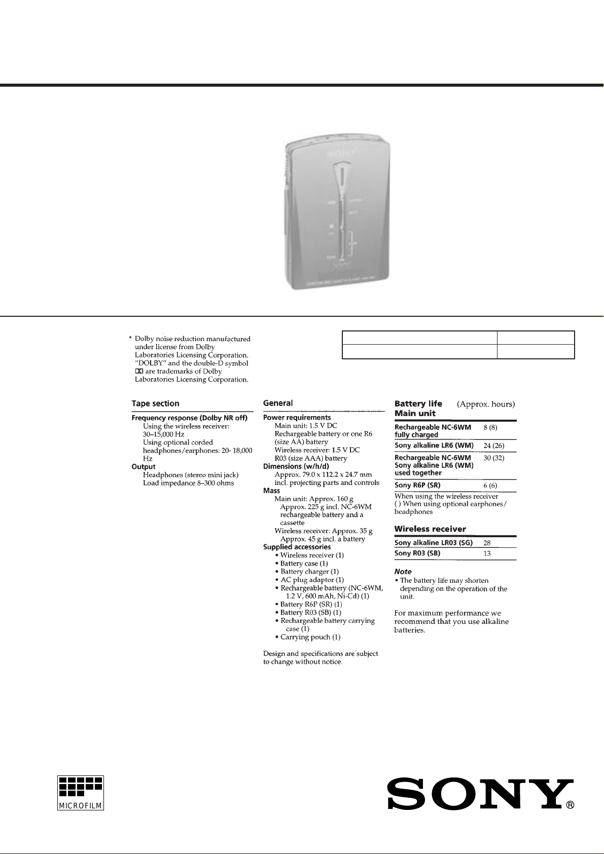
SPECIFICATIONS
Tourist Model
Model Name Using Similar Mechanism NEW
Tape Transport Mechanism Type MT-WMEX550-125
MICROFILM
CASSETTE PLAYER

SECTION 1
SERVICE NOTE
TABLE OF CONTENTS
1. SERVICE NOTE ....................................................... 2
2. GENERAL ................................................................... 5
3. DISASSEMBLY ......................................................... 6
4. MECHANICAL ADJUSTMENT.......................... 11
5. ELECTRICAL ADJUSTMENT............................ 11
6. DIAGRAMS
6-1. Block Diagram ................................................................ 13
6-2. Schematic Diagram –MAIN Section –........................... 15
6-3. Printed wiring Board –MAIN Section –......................... 19
6-4. Printed wiring Board – TMR Section –.......................... 22
6-5. Schematic Diagram – TMR Section –............................ 25
6-6. IC Pin Function Description ........................................... 29
7. EXPLODED VIEWS ................................................ 30
8. ELECTRICAL PARTS LIST ............................... 33
Service Mode
Mode for operating the mechanism section with the MAIN board
and TMR board opened.
1. Setting
1) Refer to “3. Disassembly”, and remove the cabinet and open
the MAIN board and TMR board.
2) Connect the motor and plunger to the MAIN board using
jumper wires. These can be connected easily with the use of
the extension tool (1-769-143-11) (ten in one set).
3) Turn OFF the [BLSKIP] switch (S703).
4) Connect the MAIN board to the TMR board using flexible
board for service only.
5) Press the œREPEAT switch (S3), [FF] switch (S2) and
supply 1.2V to the ‘ and ’ terminals of the battery using a
regulated power supply.
2. Preset state
T o set the PLAY , FF, REW modes, the preset state must be set.
1) Check that the lever (SW) and F/R switch (S702) are set to the
center position. If not, set the preset state as follows.
2) Move the F/R switch (S702) to the side which the lever (SW)
is facing.
3) The lever (SW) will move when the regulated power supply
switch is set to OFF once and then set to ON. Move the F/R
switch (S702) according to this timing and set to the center
position.
Notes on chip component replacement
• Never reuse a disconnected chip component.
• Notice that the minus side of a tantalum capacitor may be dam-
aged by heat.
Flexible Circuit Board Repairing
• Keep the temperature of the soldering iron around 270 ˚C dur-
ing repairing.
• Do not touch the soldering iron on the same conductor of the
circuit board (within 3 times).
• Be careful not to apply force on the conductor when soldering
or unsoldering.
3. FF, REW Modes
1) Check that the preset state is set and press the
and [REW] switches.
4. PLAY mode
1) Check that the preset state is set.
2) Pressing the œREPEAT switch on the keyboard unit will
move the lever (SW) once to war ds the F side and then to the R
side. Moving the F/R switch (S702) according to this timing
will set the PLA Y mode (R side). Pressing the œREPEA T
switch another time and moving the F/R switch (S702) according to the movement of the lev er (SW) will set the PLAY
(F side) mode.
Note 1: If the above fails, perform from preset again.
Note 2: Do not touch the œ, p, FF, REW switches with your
hands, but using a stick with a round tip.
Note 3: When using headphones, the timing for moving the S702
can be determined from the beep sound.
[FF]
SAFETY-RELATED COMPONENT WARNING!!
COMPONENTS IDENTIFIED BY MARK ! OR DOTTED
LINE WITH MARK ! ON THE SCHEMATIC DIAGRAMS
AND IN THE PARTS LIST ARE CRITICAL TO SAFE
OPERATION. REPLACE THESE COMPONENTS WITH
SONY PARTS WHOSE PART NUMBERS APPEAR AS
SHOWN IN THIS MANUAL OR IN SUPPLEMENTS PUBLISHED BY SONY.
– 2 –
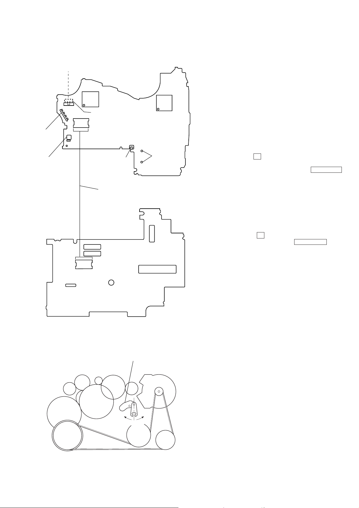
MAIN Board
— Side B —
Side F
N n
Connect to
motor
Battery
terminal (+)
TMR Board
— Side A —
Center
Side R
IC701
S702 F/R Switch
(FWD
n
STOPnREW)
Battery
terminal (–)
Flexible board for service only
IC301
Connect to
plunger
Precaution
When act repair, take the main unit and wireless recei ver of a customer, because rewriting ID code to some parts replacement.
After repair check the main unit action control from the wireless
receiver.
Rewriting ID Code
The main unit action control from the wireless receiver in this set.
Make a 14 ID codes (0001 ~ 1110) and each set include, because
protecting wrong action from another set operation signals.
The ID code rewrite to wireless receiver replacement and EEPR OM
(IC704) replacement (Lost of ID code data.)
Method
1. Turn ON the WIRELESS switch (S704) of main unit. (Don't
connect to headphones.)
2. Press the two buttons p and [REW] simultaneously and the
LED light of main unit.
3. Straighten headphones cord and press continue
œ
REPEAT
button, then LCD displays ID code. (4 figure, 0 or 1 characters.)
4. Battery remove, the ID code rewriting complete.
5. After repair check the action.
Check ID code main units
1. Turn ON the WIRELESS switch (S704) of main unit. (Don't
connect to headphones.)
2. Straighten headphones cord and close the main unit.
3. Press the two buttons p and [FF] simultaneously and the
LED light ON of main unit, then press œREPEAT button
and LCD displays main units ID code of wireless receiver.
Lever (SW)
CN1
side R
lever (SW)
side F
senter
Check ID code wireless receivers
1. Press continue
[CH] button, and insert battery of wireless re-
ceiver
2. LCD displays wireless receivers ID code.
– 3 –
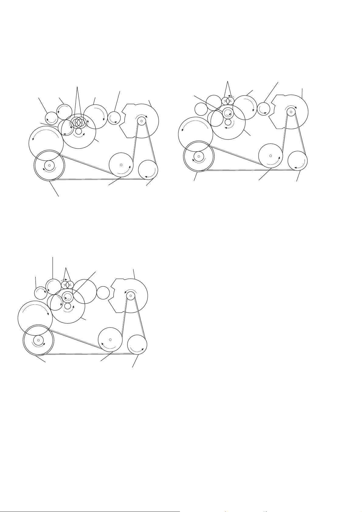
Rotation system
y
Rotation system during PLAY.
gear (NR)
(REV: right side/
gear (REEL)
(T side)
gear (TA)
gear (Y)
FWD: left side)
gear (TB)
flywheel (N) ass’y
gear (REEL)
(S side)
gear (S)
clutch ass’y (M)
Pulley (reverse)flywheel (R) ass’y
motor pulle
Rotation system during REW.
gear (FR)
(REW: right side)
gear (NR)
gear (Y)
flywheel (N) ass’y
gear (S)
clutch ass’y (M)
flywheel (R) ass’y
gear (REEL)
(S side)
motor pulley
pulley (reverse)
Rotation system during FF.
gear (TB)
gear (FR)
gear (REEL)
(T side)
gear (Y)
flywheel (N) ass’y
(FF: left side)
gear (NR)
clutch ass’y (M)
flywheel (R) ass’y
pulley (reverse)
motor pulley
– 4 –
SECTION 2
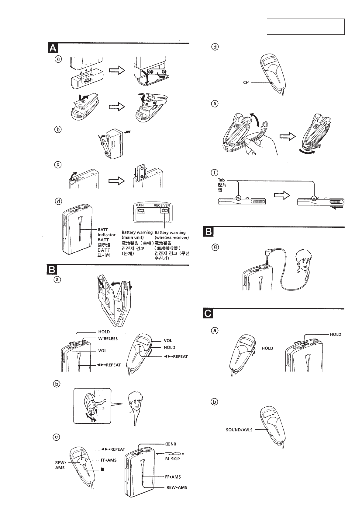
GENERAL
This section is extracted from
instructio n man ual.
– 5 –
• This set can be disassembled in the order shown below.
SECTION 3
DISASSEMBLY
SET
Note: Follow the disassembly procedure in the numerical order given.
CASSETTE
LID ASS'Y
(Page 6)
CASE SUB
ASS'Y
(Page 7)
REEL
ORNAMENT
ASS'Y
(Page 7)
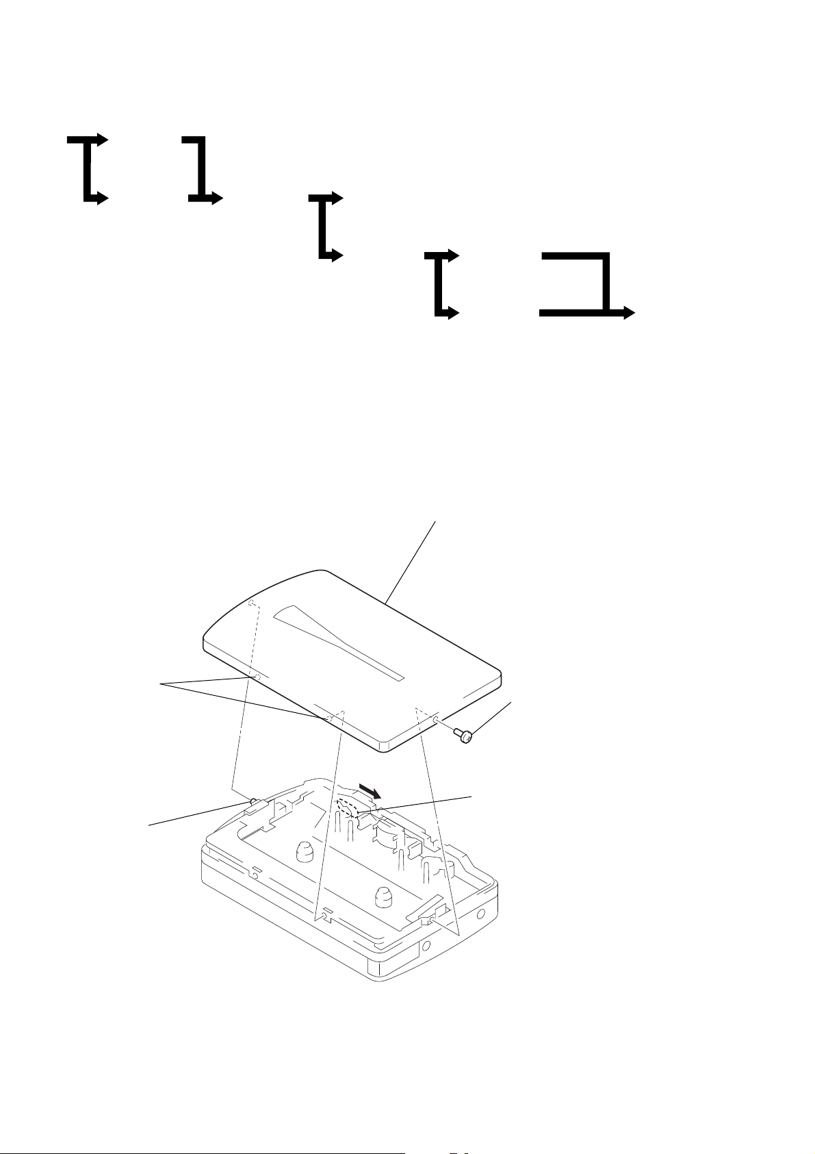
CASSETTE LID ASS’Y
MAGNETIC HEAD (HP901)
(Page 8)
TMR BOARD
(PAGE 8)
5
cassette lid ass'y
MAIN BOARD
(Page 9)
BELT
(Page 10)
MOTOR (M901)
(Page 10)
3
two bosses
4
boss
2
serrat IB lock
1
Open the cassette lid ass'y.
– 6 –
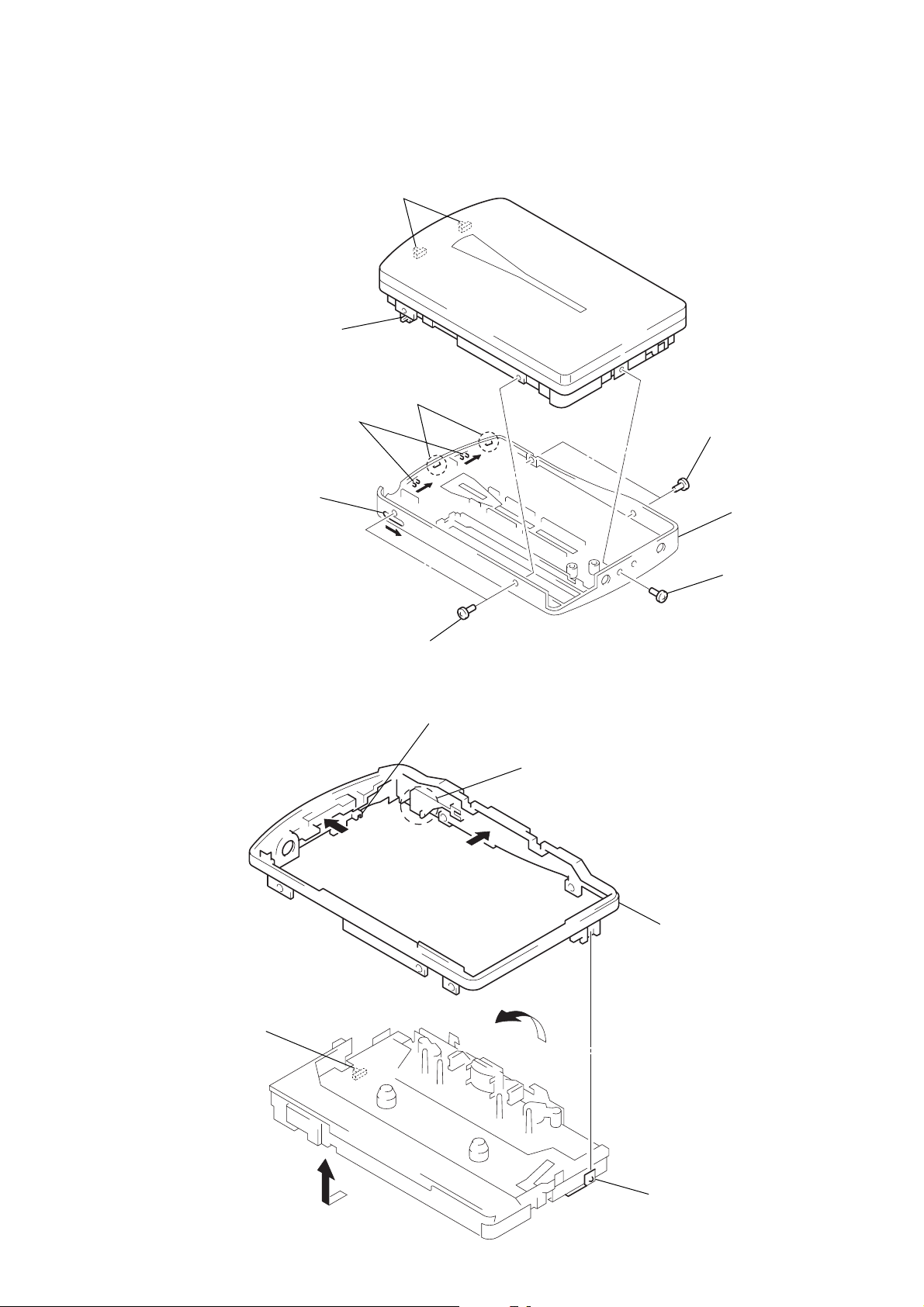
CASE SUB ASS'Y
y
Note on installation:
Adjust to switch A, switch
and knob A, knob B.
B
switch
knob
knob
B
B
switch
A
A
3
two claws
2
two serrat IB locks
4
case sub ass'
REEL ORNAMENT ASS'Y
Note on installation:
Adjust the knob (HOLD) and switch.
switch
2
two serrat IB locks
B
knob (HOLD)
A
1
Push the reel ornamental assembly
toward direction
the pawl of the knob(OPEN).
C
A
, and disengage
3
Opening the reel ornamental
assembly (3) toward direction
shift it toward direction
4
Remove the reel ornament ass'y
to direction of the arrow
1
serrat IB lock
C
D
B
,
.
D
– 7 –
2
terminal board, battery
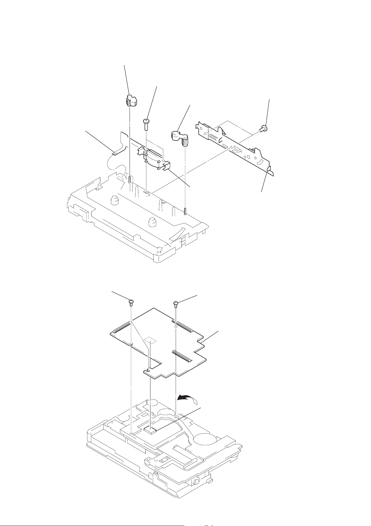
MAGNETIC HEAD (HP901)
4
flexible board
(CN301)
1
pinch lever (N) ass'y
5
two screws (M1.4 × 7.2)
1
pinch lever (R) ass'y
6
magnetic head
(HP901)
2
two screws (IB lock)
3
bracket ass'y
TMR BOARD
1
two special head screws
2
serrat IB lock
4
TMR board
A
Raise the TMR board from direction A
3
to disconnect the connector (CN701).
– 8 –
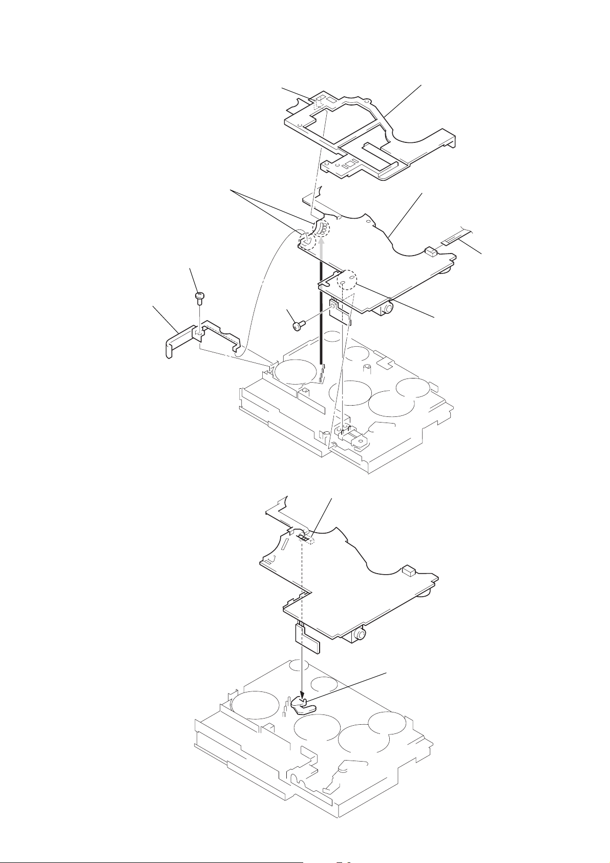
MAIN BOARD
5
terminal board
ass'y, battery
1
claw
3
Remove the solders of motoer (M901) and
terminal board ass'y battery.
4
screw
7
screw
(IB lock)
2
guide (board)
8
MAIN board
3
Remove the solders of
plunger solenoid.
6
flexible board
(CN301)
Note on installation:
When the MAIN board, align
the switch (S702) with the
lever (SW) correctly.
S702
lever (SW)
– 9 –
 Loading...