

Sony WMGX-221 Service manual
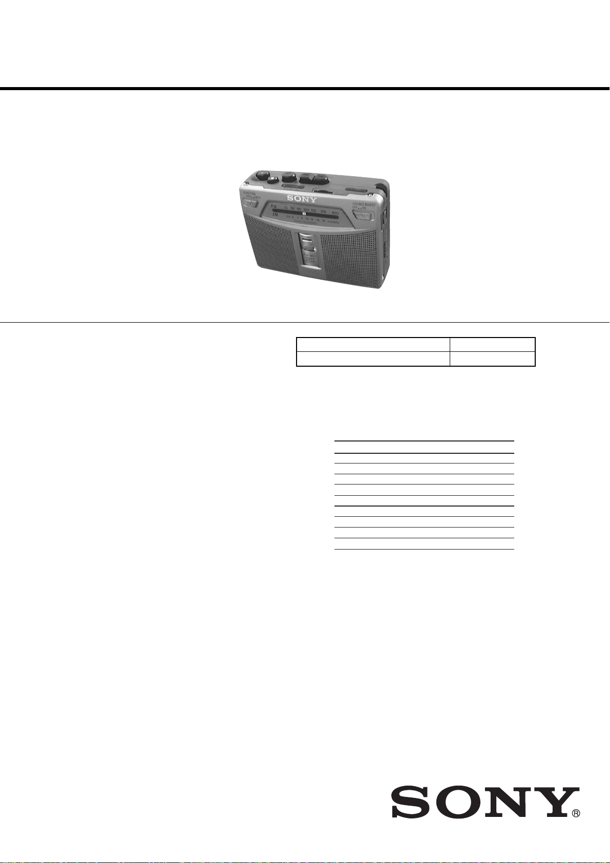
WM-GX221
SERVICE MANUAL
Ver 1.1 2002. 06
Model Name Using Similar Mechanism New
Tape Transport Mechanism Type MT-WMGX221-175
SPECIFICATIONS
US Model
E Model
Chinese Model
Frequency range
FM: 87.5-108 MHz (Italy and Saudi Arabia)
87.6-108 MHz (North, Central and South America)
87.6-107.9 MHz (Other countries)
AM: 526.5-1 606.5 kHz (Italy and Saudi Arabia)
530-1 710 kHz (North, Central and South America)
531-1 602 kHz (Other countries)
Frequency response Playback: 40 - 15 000 Hz
Input Microphone (MIC) jack
Output Headphones (i) jack
Power requirements 3 V DC batteries R6 (size AA)
Dimensions (w/h/d) Approx. 112.0
Mass Approx. 190 g (6.8oz) (main unit
Supplied accessories Stereo headphones or earphones (1)
Design and specifications are subject to change without notice.
Recording: 100 - 8 000 Hz (when
setting 2x REC TIME to NORM)
Load impedance 8 - 300 Ω
External DC 3V power sources
1
(4
/
projecting parts and controls
only)
Stereo microphone (1)
Carrying case (1)
×
3 1/
2
×
82.5 × 38.0 mm
×
1 1/2 inches), excl.
4
×
2
Battery life (Approx. hours) (JEITA*)
Sony alkaline LR6(SG)
(using headphones/earphones)
playback 24 7
radio 48 15
mic recording 20 4.5
radio recording 12 3
(using the speakers)
playback 15 4.5
radio 26 6
radio recording 11.5 3
*Measured value by the standard of JEITA (Japan
Electronics and Information Technology Industries
Association) (using a Sony HF series cassette tape).
**When using Sony LR6(SG) “STAMINA” alkaline dry
batteries (produced in Japan).
Note
•The battery life may be shorter depending on the
operating condition, the surrounding temperature
and battery type.
** Sony R6P(SR)
9-873-412-02
2002F1600-1
© 2002.06
RADIO CASSETTE-CORDER
Sony Corporation
Personal Audio Company
Published by Sony Engineering Corporation

WM-GX221
TABLE OF CONTENTS
1. SERVICE NOTE ··············································································· 3
2. GENERAL ·························································································· 4
3. DISASSEMBLY ················································································ 5
3-1. Panel (Cabinet Front), Cabinet (Front) Assy ·································· 5
3-2. MAIN Board, Mechanism Deck (MT-WMGX221-175) ················ 6
3-3. HE901, HRP901, M601, Belts························································ 7
3-4. SUB Board ······················································································ 7
4. MECHANICAL ADJUSTMENT ·················································· 8
5. ELECTRICAL ADJUSTMENT······················································ 8
6. DIAGRAMS ······················································································ 10
6-1. Block Diagram – Tuner Section –················································· 11
6-2. Block Diagram – Main Section – ················································· 12
6-3. Printed Wiring Boards ·································································· 13
6-4. Schematic Diagram – MAIN Board (1/2) –·································· 14
6-5. Schematic Diagram – MAIN Board (2/2) –·································· 15
6-6. IC Block Diagrams ······································································· 16
7. EXPLODED VIEWS ······································································ 17
7-1. Overall Section ············································································· 17
7-2. Cabinet (Front) Section································································· 18
7-3. Mechanism Deck Block-1 (MT-WMGX221-175) ······················· 19
7-4. Mechanism Deck Block-2 (MT-WMGX221-175) ······················· 20
8. ELECTRICAL PARTS LIST ······················································· 21
Notes on chip component replacement
• Never reuse a disconnected chip component.
• Notice that the minus side of a tantalum capacitor may be
damaged by heat.
Flexible Circuit Board Repairing
• Keep the temperature of soldering iron around 270˚C
during repairing.
• Do not touch the soldering iron on the same conductor of the
circuit board (within 3 times).
• Be careful not to apply force on the conductor when soldering
or unsoldering.
2
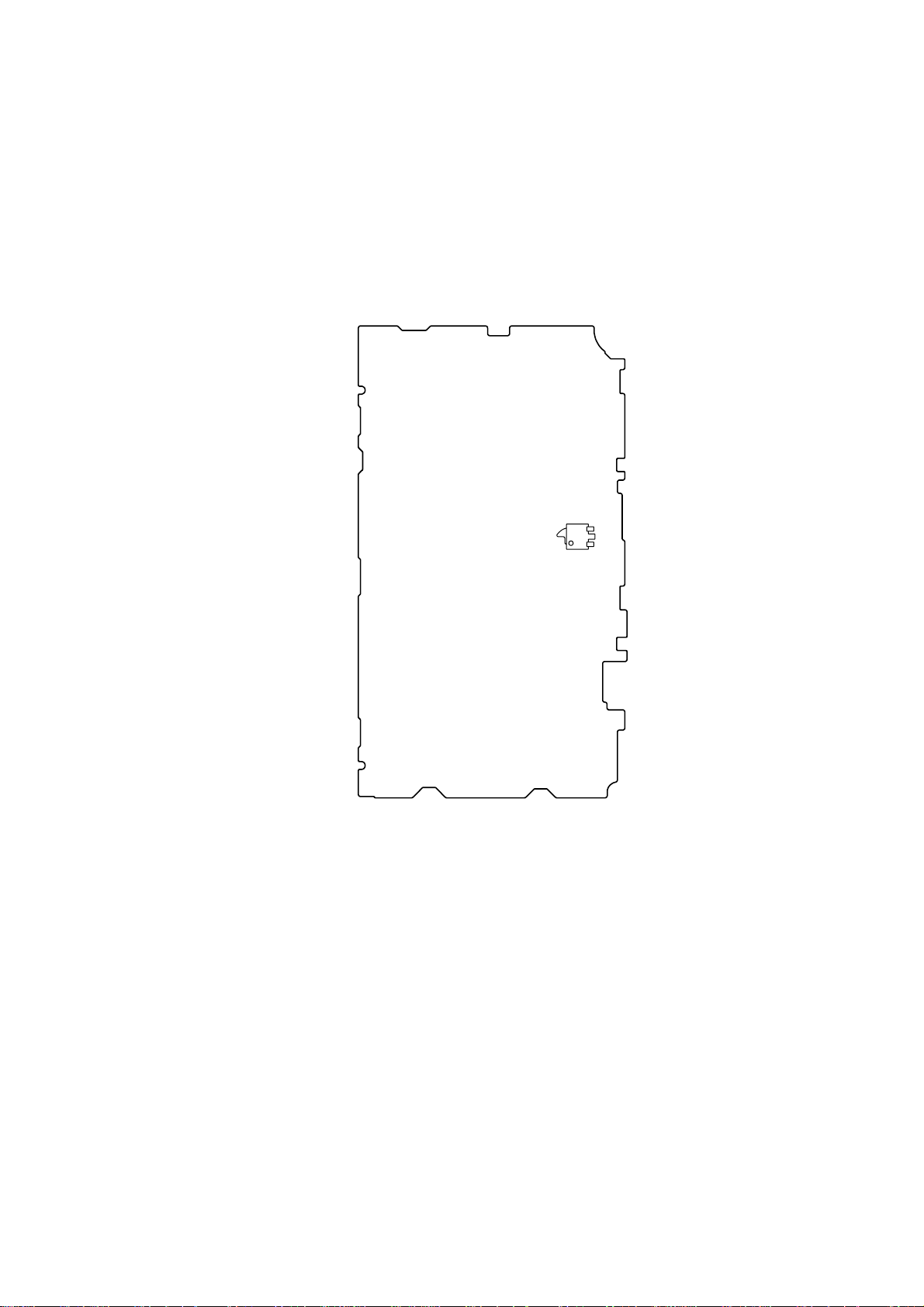
SECTION 1
SERVICE NOTE
In this set, record/play mode is detected using the switch S704 (TAPE POWER).
S704 is mounted on the MAIN board. If MAIN board is removed, it becomes impossible to detect
record/play mode.
Where MAIN board is removed, when you measure operation and voltage of each part of the mechanism
deck, please turn on S704.
– MAIN BOARD (SIDE A) —
WM-GX221
S704
3
WM-GX221
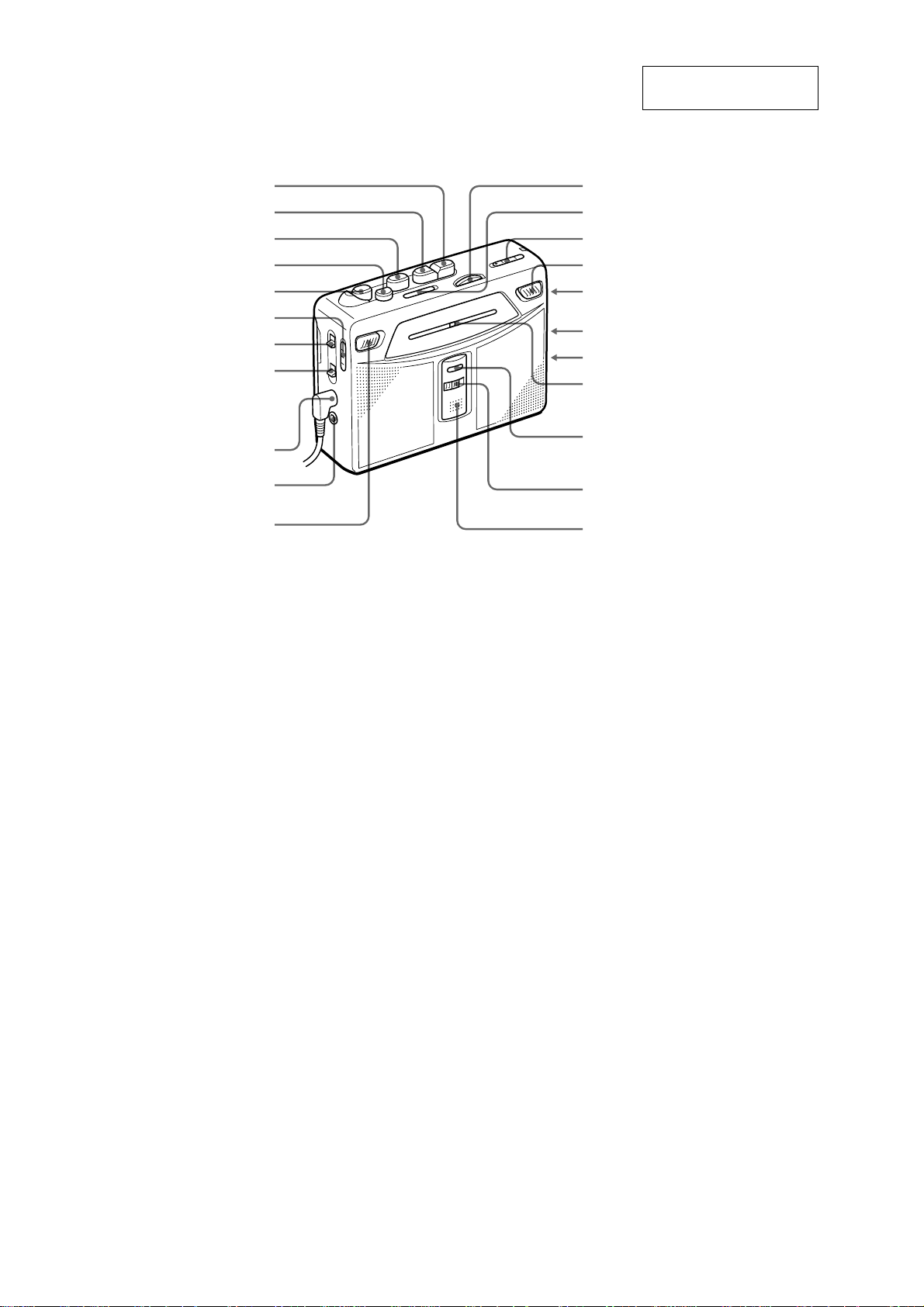
• LOCATION OF CONTROLS
SECTION 2
GENERAL
This section is extracted
from instruction manual.
M FF/CUE
m REW/REVIEW
N PLAY**
x STOP
z REC
AVLS (NORM/LIMIT)
ISS
NORM/CrO2/METAL•
MIC (PLUG IN POWER)**
FLUNCTION (TAPE/RADIO)
FM ST/MONO
DX/LOCAL
* There is a tactile dot beside VOL on the main unit to show the direction to turn up the
volume.
** The button/jack has a tactile dot.
TUNING
PAUSE
BAND (FM/AM)
SOUND BOOST
(OFF/ON)
VOL *
SPEAKER/ i
DC IN 3V
Tuning indicator
REC/BATT indicator
i
2x REC TIME
(NORM/DOUBLE)
Built-in microphone
4
Note : Disassemble the unit in the order as shown below.
)
WM-GX221
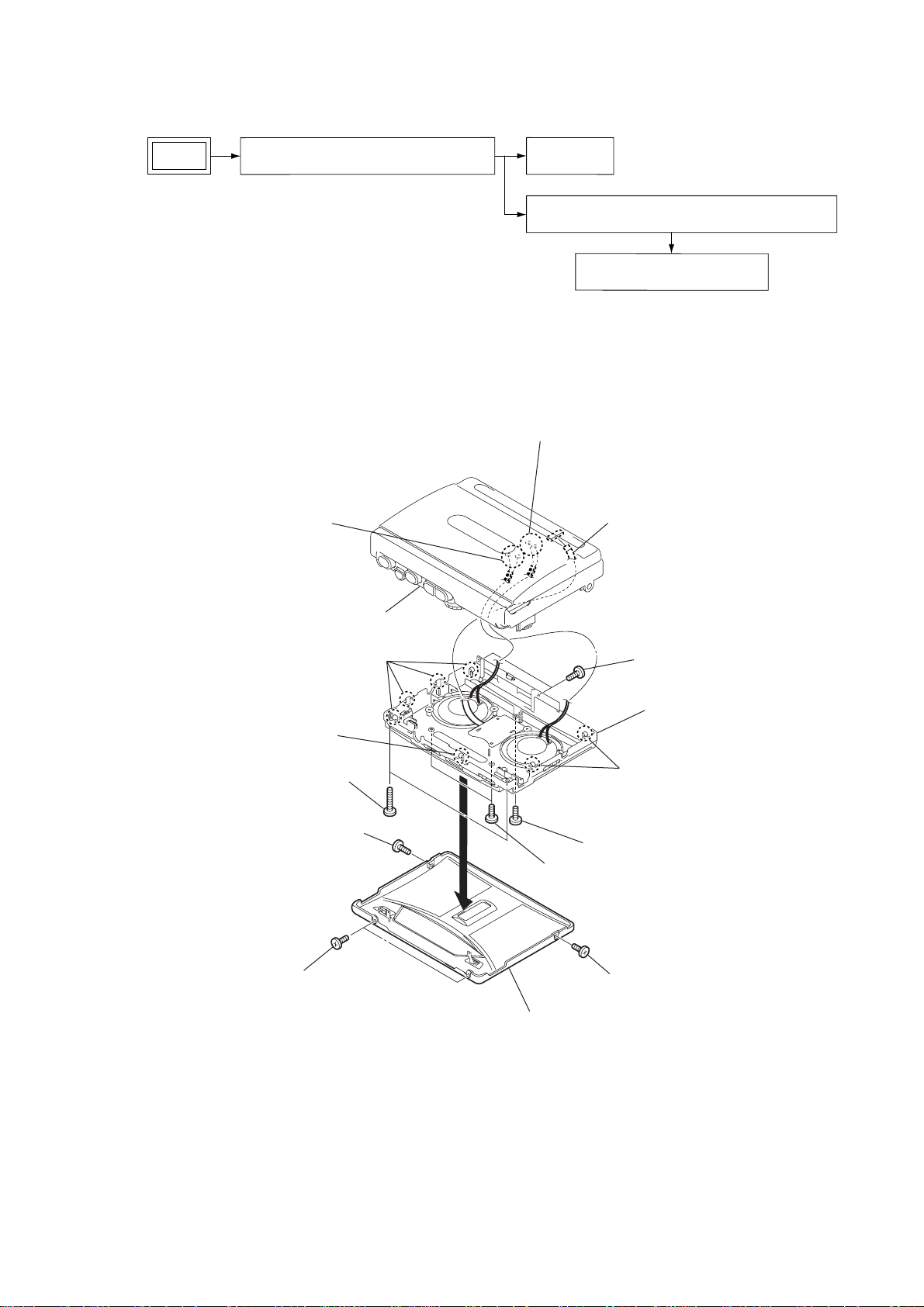
SECTION 3
DISASSEMBLY
Set
Panel (cabinet front), Cabinet (front) assy
Note : Follow the disassembly procedure in the numerical order given.
3-1. PANEL (CABINET FRONT), CABINET (FRONT) ASSY
Remove solder.
6
(two places)
Remove solder.
6
(two places)
SUB board
MAIN board, Mechanism deck (MT-WMGX221-175)
HE901, HRP901, M601, Belts
flexible board
5
4
two screws (B1.7 × 9)
3
screw (B1.7 × 1.4)
1
two screws (B1.7 × 1.4)
1
cabinet center
four claws
4
claw
2
4
screw
3
two screws
3
screw (B1.7 × 1.4)
1
panel (cabinet front)
two screws (B1.7 × 1.4
3
cabinet (front) assy
two claws
5
WM-GX221
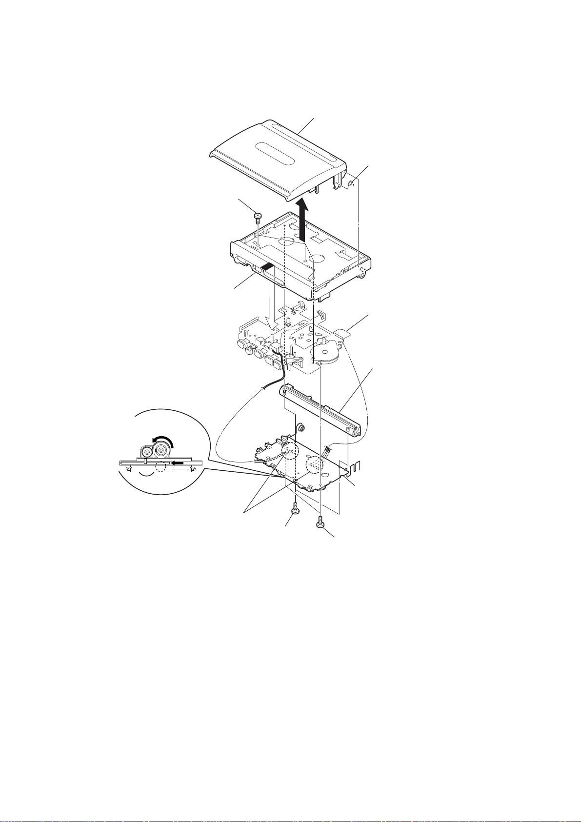
3-2. MAIN BOARD, MECHANISM DECK (MT-WMGX221-175)
three screws (B1.7 × 9)
3
cassette holder sub assy
spring (torsion)
2
1
cabinet center
<Caution of the pointer attachment>
The pointer is slid, even a stopper is
brougth near, and CV1 is turned with
all its might clockwise, and is attached.
Remove solder
8
(four places)
4
5
two screws
9
two screws
6
MT-WMGX221-175
joint cover
7
MAIN board
6
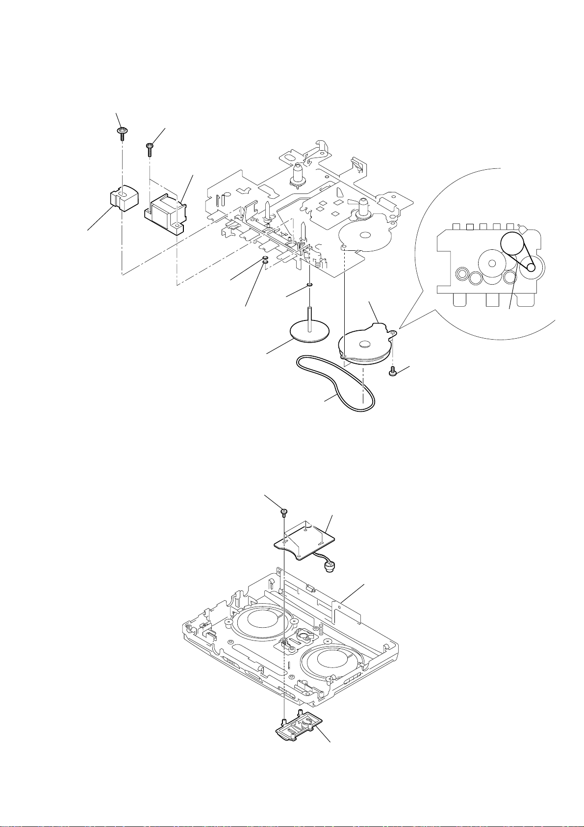
3-3. HE901, HRP901, M601, BELTS
y
screw
0
8
two screws
9
HRP901
(REC/PB head)
HE901
qa
(erase head)
6
washer
(stopper N)
5
washer
7
washer
M601
3
(capstan/reel
motor)
WM-GX221
z
Attaching belt (CAP)
and belt (pulley).
belt (CAP)
3-4. SUB BOARD
capstan fly assy (AR)
6
four screws (B1.7)
1
1
belt (CAP)
SUB board
2
two screws (M1.4)
2
cabinet (front) ass
panel (MIC)
7
WM-GX221
r
SECTION 4
MECHANICAL ADJUSTMENT
SECTION 5
ELECTRICAL ADJUSTMENT
PRECAUTION
1. Clean the following parts with a denatured-alcohol-moistened
swab:
record/playback/erase head pinch roller
rubber belts capstan
2. Demagnetize the record/playback head with a head demagnet-
izer. (Do not bring a head demagnetizer close to the erase
head.)
3. Do not use a magnetized screwdriver for the adjustments.
4. The adjustments should be performed with the rated power
supply voltage unless otherwise noted.
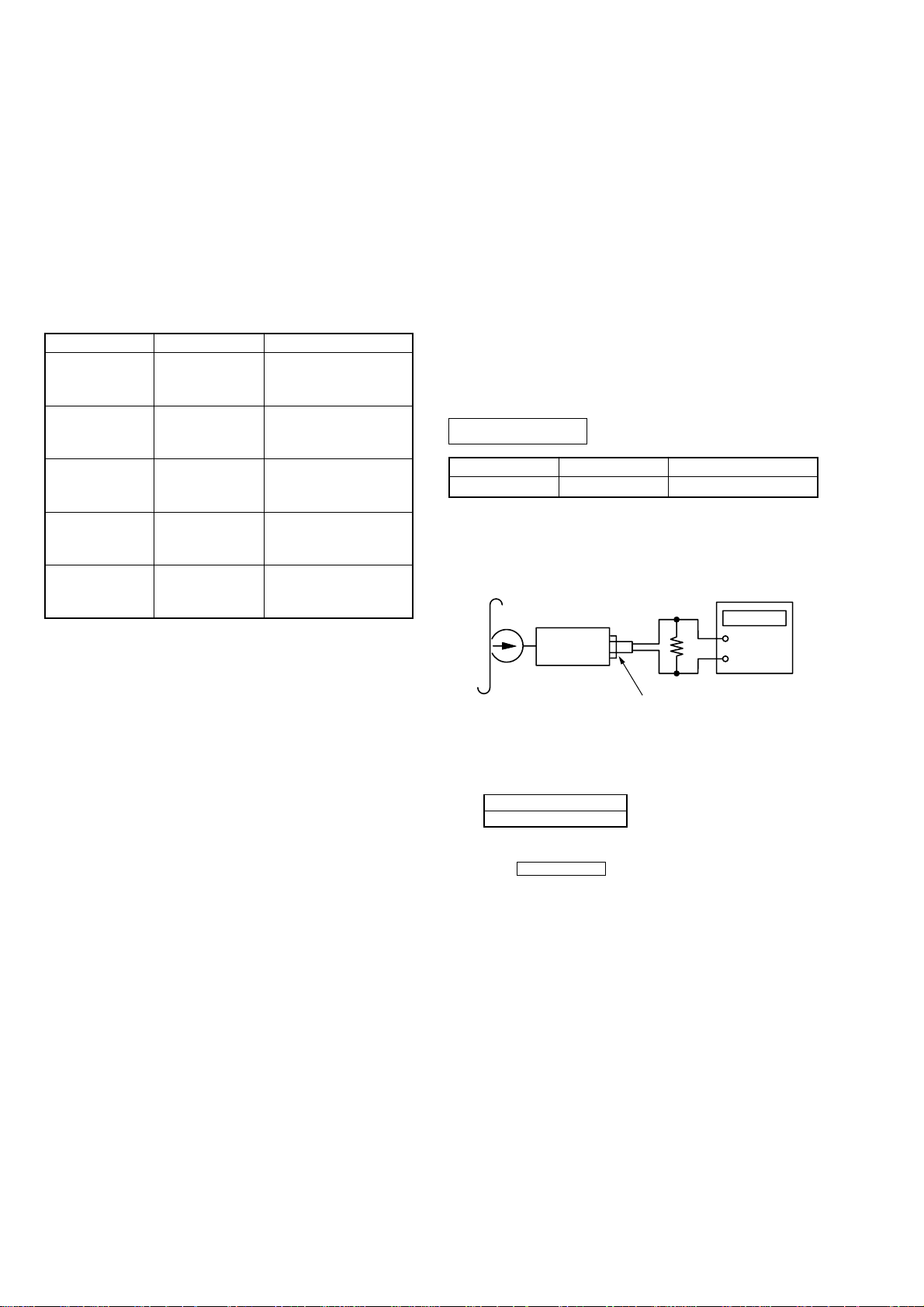
• Torque Measurement
Mode
FWD
FWD
Back Tension
REV
REV
Back Tension
FF, REW
Torque Meter
CQ-102C
CQ-102C
CQ-102RC
CQ-102RC
CQ-201B
Meter Reading
19.6 to 29.4 mN•m
(20 to 30 g•cm)
(0.28 to 0.42 oz•inch)
Less than 1.96 mN•m
(Less than 2.0g•cm)
(Less than 0.028 oz•inch)
19.6 to 29.4 mN•m
(20 to 30 g•cm)
(0.28 to 0.42 oz•inch)
Less than 1.96 mN•m
(Less than 2.0g•cm)
(Less than 0.028 oz•inch)
More than 39.2 mN•m
(More than 40 g•cm)
(More than 0.56 oz•inch)
PRECAUTION
1. Specified voltage: 2.5 V (DC)
2. Switch and control position
VOL : MAX
SPEAKER : OFF
AVLS : NORM
SOUND BOOST : OFF
PB EQ : NORM
PAUSE : OFF
ISS : 1
FM SENSE : DX
(US, 5E)
FM MODE : FM ST
(EXCEPT US, 5E)
2X REC TIME : NORM
• Abbreviation
5E : E model with the indication of the country of origin.
TAPE SECTION
Tape
WS-48A
Tape Speed Adjustment
Procedure:
Test tape
WS-48A
(3kHz, 0dB)
Signal
3 kHz, 0 dB
Ω
(EXCEPT US MODEL)
16
32 Ω (US MODEL)
Used for
Tape Speed Adjustment
Set
2
jack (J301)
1. Enter the FWD playback mode.
2. Adjust RV601 so that the v alue of the frequency counter reading
becomes 3,000 Hz.
Specification value:
Frequency counter
2,985 Hz – 3,015 Hz
3. Check that the frequency deviation at the beginning and ending
of a tape is within 1.5 % (45 Hz).
4. Set the 2x REC TIME switch to DOUBLE (2.4 cm/s).
5. Adjust RV602 so that the v alue of the frequency counter reading
becomes 1,500 Hz.
Adjustment Location : MAIN board (see page 9)
+
–
Frequency counte
8
 Loading...