

Sony WM-GX100 Service Manual
WM-GX100
SERVICE MANUAL
Ver 1.0 2000.10
SPECIFICATIONS
• Frequency range
FM: 65.0 - 107.9 MHz (Eastern Europe)
87.5 - 108 MHz (Italy and Saudi Arabia)
87.6 - 108 MHz (North, Central and South America)
87.6 - 107.9 MHz (Other countries)
AM:526.5 - 1,606.5 kHz (Italy and Saudi Arabia)
530 - 1,710 kHz (North, Central and South America)
531 - 1,602 kHz (Other countries)
• Power requirement
– 3V DC batteries R6 (AA) x 2
– External DC 3 V power sources
• Dimensions
88.8 x 118.6 x 38.0 mm (3 1⁄2 x 4 3⁄4 x 1 1⁄2 inches) (w/h/d)
• Mass
Approx. 160 g (5.7 oz)
• Supplied accessories
Stereo headphones or Stereo earphones (1), Belt clip (1),
Stereo microphone (1)
E Model
Chinese Model
Model Name Using Mechanism Type WM-SR1
Similar Mechanism Tape Transport MF-WMSR1-114
Battery life (approximate hours) (EIAJ*)
Sony alkaline LR6 (SG)** Sony R6P (SR)
playback 24 7
radio 50 16
mic recording 11 3.5
radio recording 10 2.5
* Measured value by the standard of EIAJ (Electronic Industries
Association of Japan). (Using a Sony HF series cassette tape)
** When using LR6 (SG) Sony “STAMINA” alkaline dry batteries
(produced in Japan).
Note
• The battery life may be shorter depending on the operating condition,
the surrounding temperature and battery type.
Design and specifications are subject to change without notice.
RADIO CASSETTE-CORDER
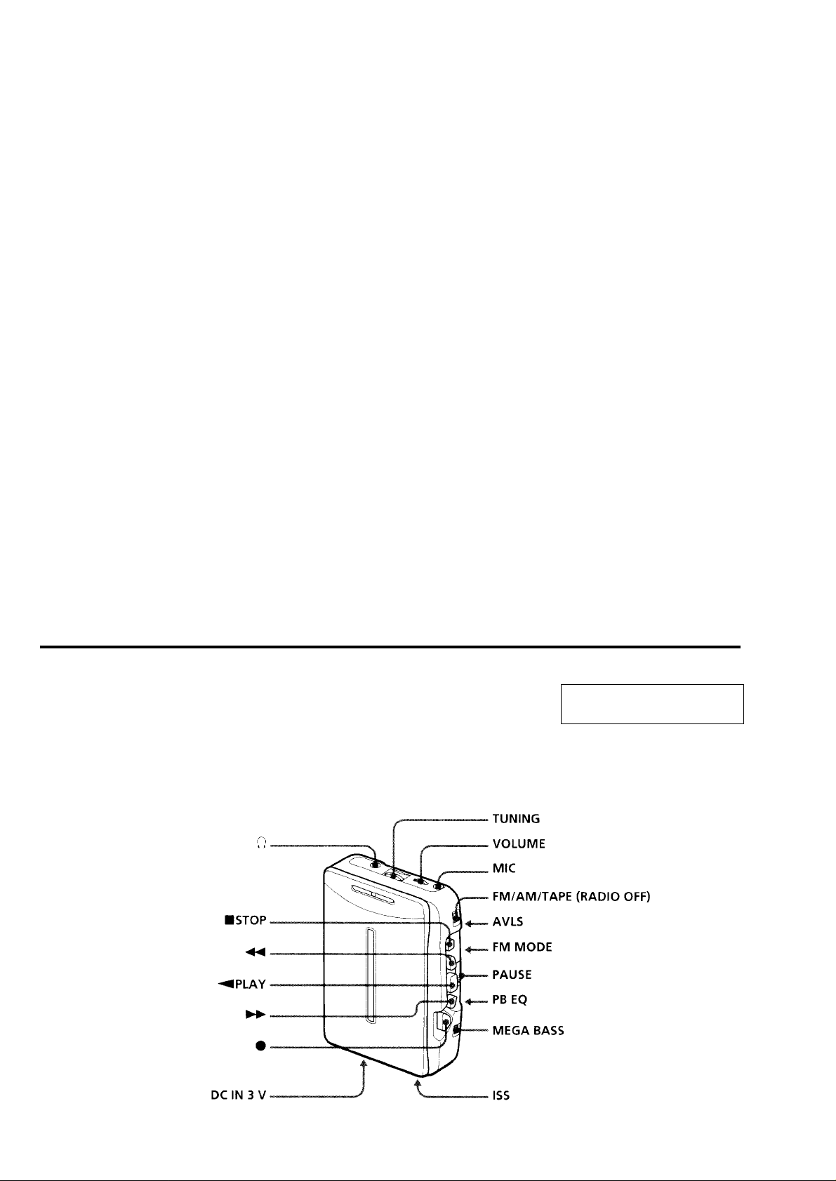
TABLE OF CONTENTS
Specifications ........................................................................... 1
1. GENERAL
Location and Function of Controls .................................... 2
Flexible Circuit Board Repairing
• Keep the temperature of the soldering iron around 270°C during
repairing.
• Do not touch the soldering iron on the same conductor of the
circuit board (within 3 times).
• Be careful not to apply force on the conductor when soldering or
unsoldering.
2. DISASSEMBLY
2-1. Cabinet (Rear)............................................................. 3
2-2. Main Board ................................................................. 4
2-3. Mechanism Deck ........................................................ 4
2-4. Motor (M901), “Head, Magnetic” (HRP901) ............ 5
2-5. Holder Sub ASSY, Cassette ........................................ 5
2-6. Setting the Pointer ...................................................... 6
3. ADJUSTMENTS
3-1. Mechanical Adjustments............................................. 7
3-2. Electrical Adjustments................................................ 7
4. DIAGRAMS
4-1. Block Diagram (1/2) ................................................... 9
4-2. Block Diagram (2/2) ..................................................11
4-3. Printed Wiring Boards .............................................. 13
4-4. Schematic Diagram (1/2).......................................... 15
4-5. Schematic Diagram (2/2).......................................... 17
5. EXPLODED VIEWS
5-1. Cabinet Section......................................................... 21
5-2. Mechanism Deck Section ......................................... 22
6. ELECTRICAL PARTS LIST................................... 23
Notes on chip component replacement
• Never reuse a disconnected chip component.
• Notice that the minus side of a tantalum capacitor may be damaged by heat.
LOCATION AND FUNCTION OF CONTROLS
SECTION 1
GENERAL
This section is extracted from
instruction manual.
SECTION 2
)
DISASSEMBLY
z
The equipment can be removed using the following procedure.
Set
Main boardCabinet (rear)
“Holder sub ASSY, Cassette”
Note : Follow the disassembly procedure in the numerical order given.
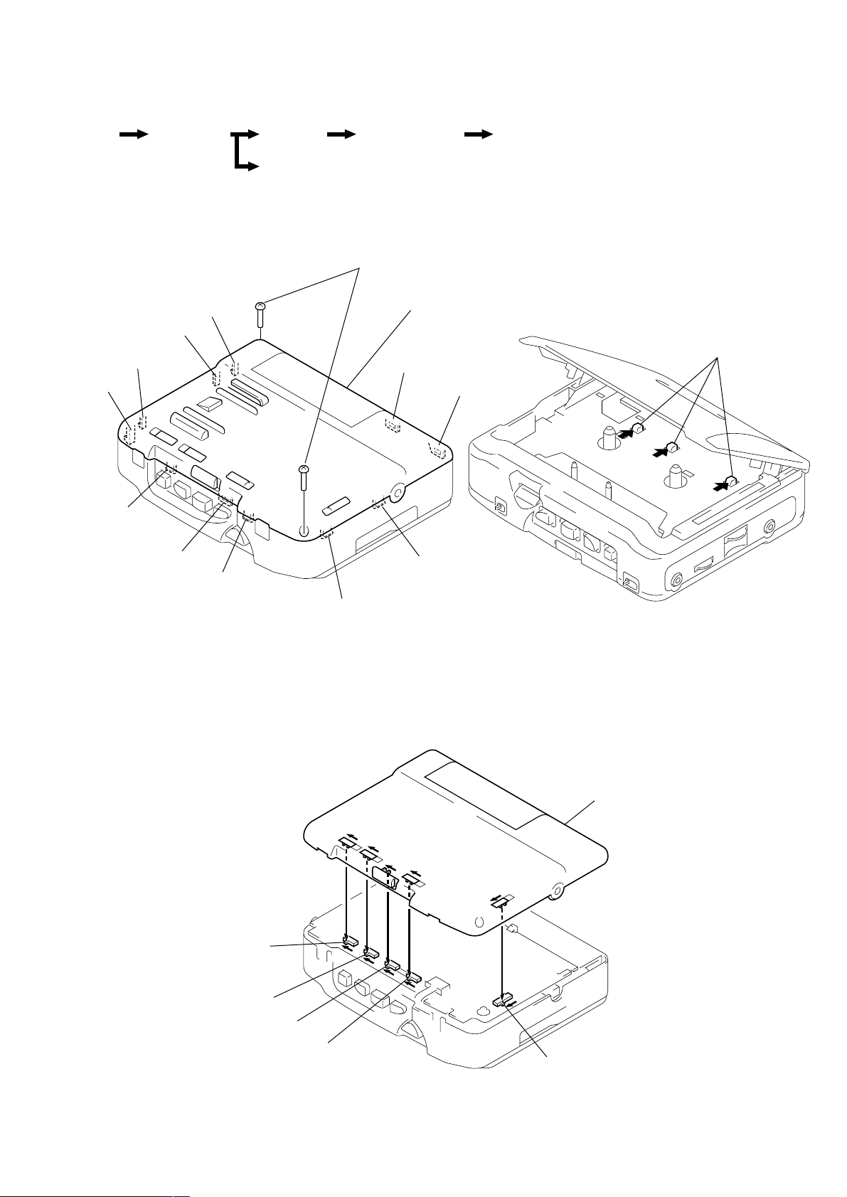
2-1. CABINET (REAR)
L
K
J
I
Mechanism deck
(MF-WMSR1-114)
1
Screws (B 1.7)
2
Cabinet (rear)
A– L
(
B
Motor (M901), “Head, Magnetic” (HRP901)
: Claws
A
C
H
G
F
E
z
CAUTIONS DURING CABINET (REAR) ASSEMBLY
Align switches and knobs with arrow direction
D
Cabinet (Front)
S305
S2
S308
S310
S307
– 3 –
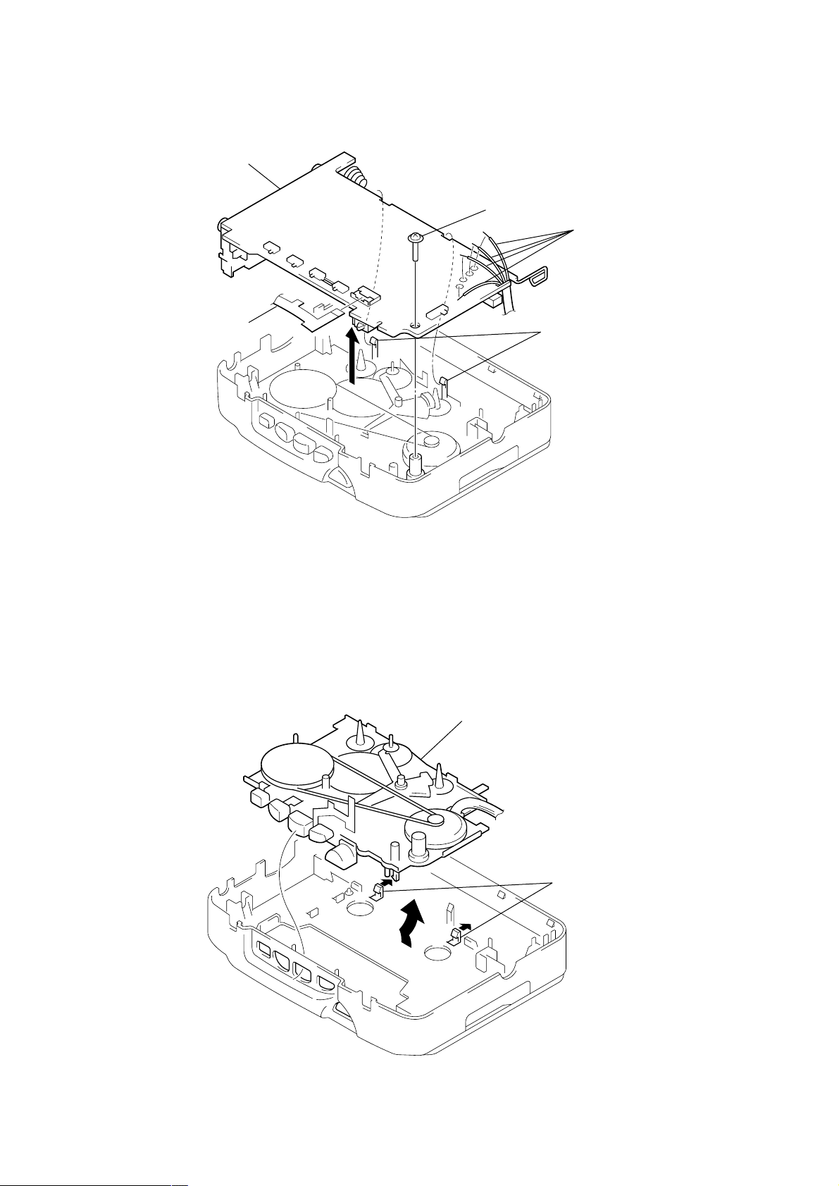
2-2. MAIN BOARD
s
2
Head flexible board
(CN301)
Main board
5
3
Screw (M1.4)
4
1
Remove solder (4 places)
(M901)
Claws
2-3. MECHANISM DECK (MF-WMSR1-114)
2
Mechanism deck
(MF-WMSR1-114)
1
Claw
– 4 –
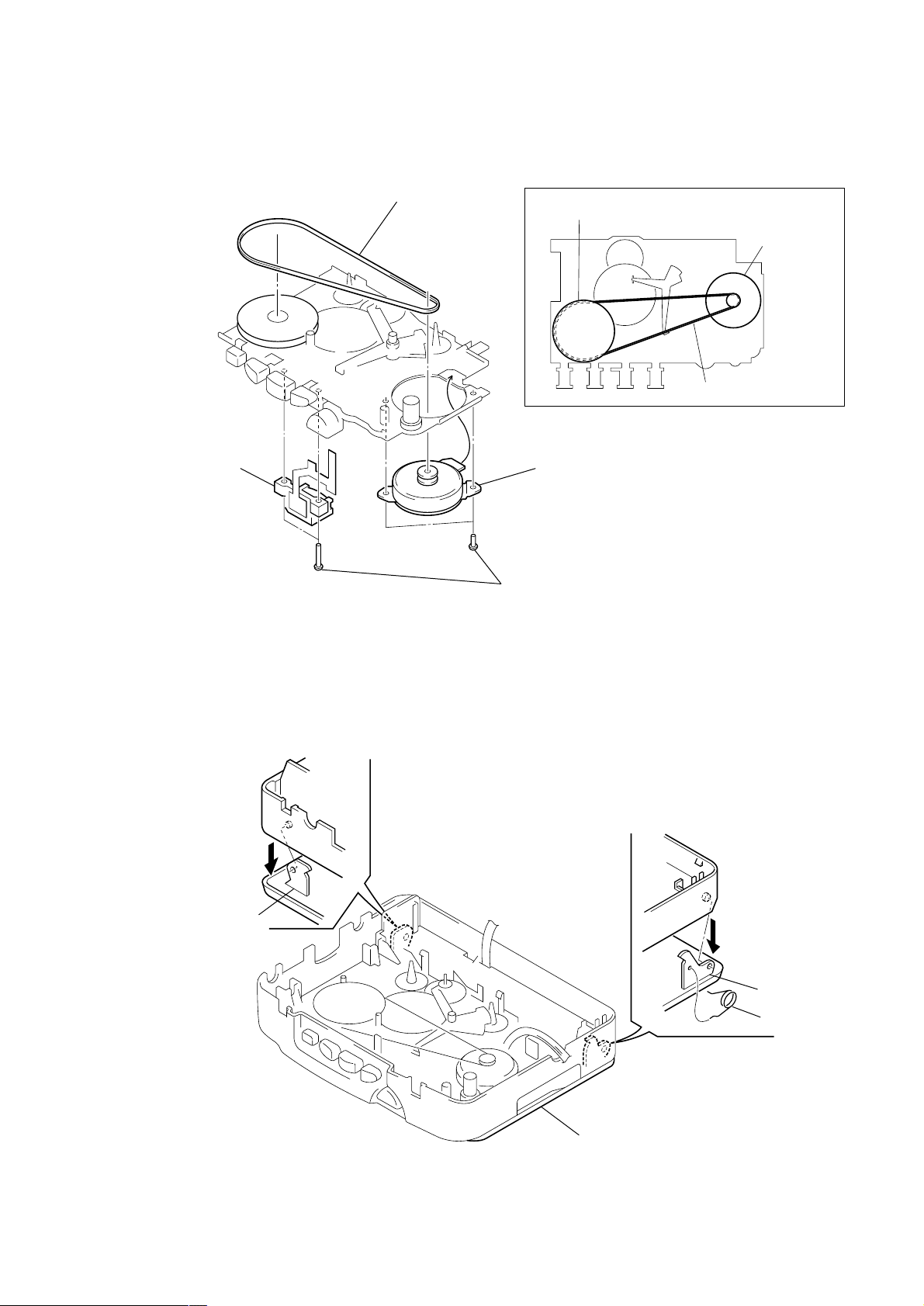
2-4. MOTOR (M901), “HEAD, MAGNETIC” (HRP901)
4
“Head, Magnetic”
(HRP901)
1
Belt
How to apply the belt
Wheel ASSY (NP), capstan
3
Motor (M901)
2
Screws (M1.4)
M901
Belt
2-5. HOLDER SUB ASSY, CASSETTE
1
Move hinge awsy
from projection
Hinge
4
Holder sub ASSY, cassette
2
1
Move hinge awsy
from projection
Hinge
3
Spring (tortion)
– 5 –
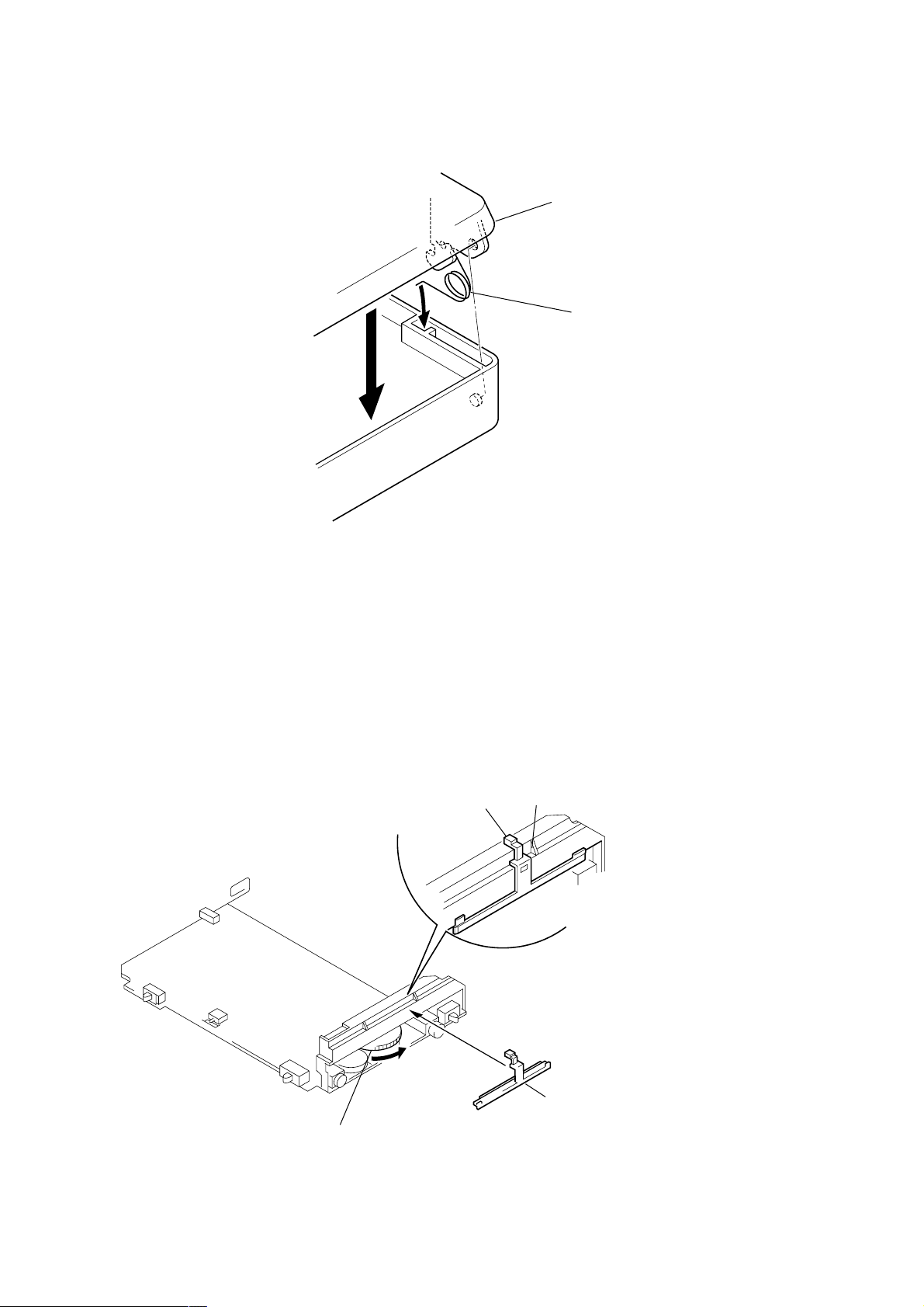
z
e
CAUTIONS DURING “HOLDER SUB ASSY, CASSETTE” ASSEMBLY
4
Holder sub ASSY, cassett
3
Close the “Holder sub ASSY,
cassette” then press it
2-6. SETTING THE POINTER
2
1
Spring (tortion)
Pointer
1
Turn the tuning knob in the arrow direction
A
Pointer
2
Install the pointer and
align it with
A
section
– 6 –
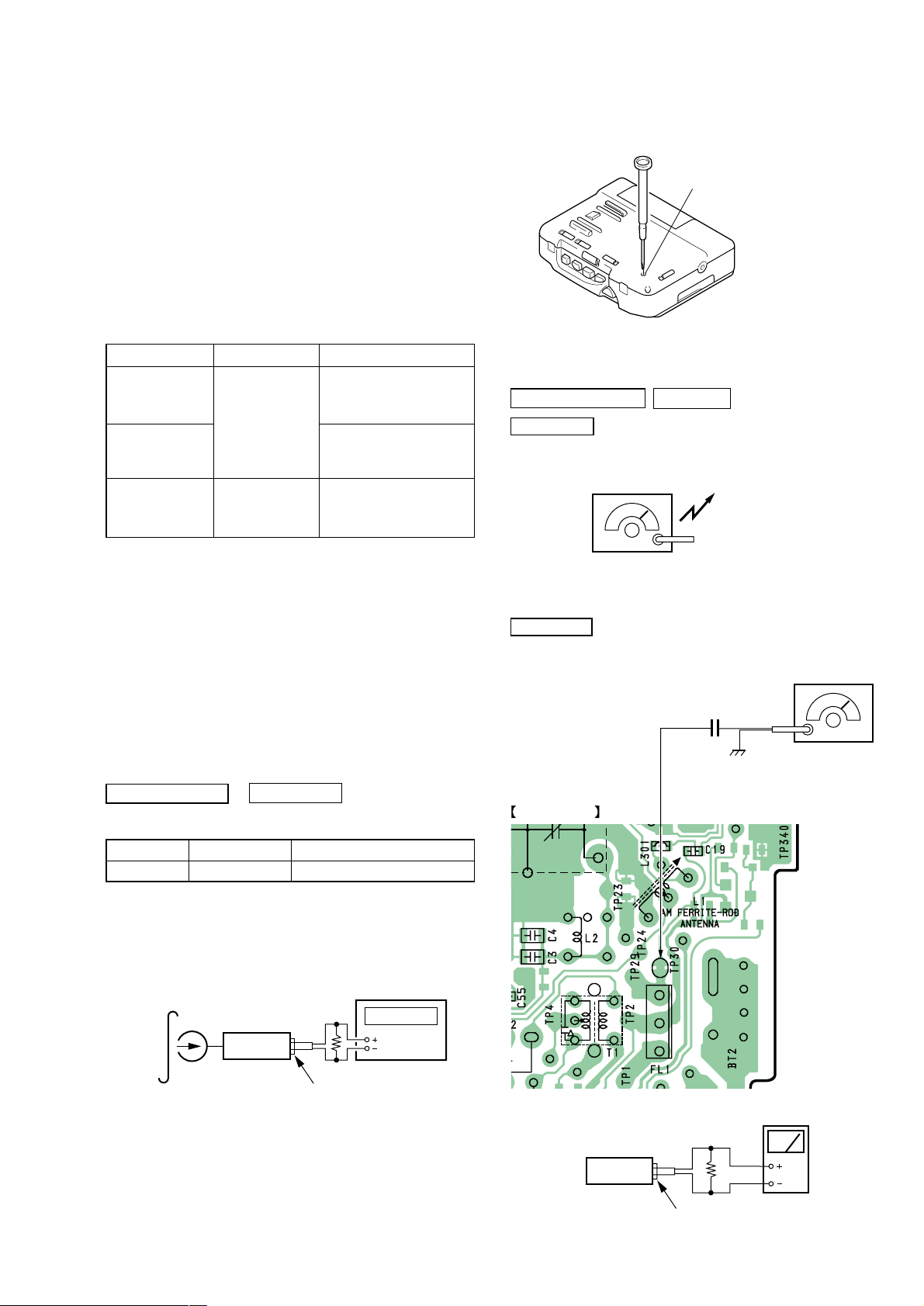
SECTION 3
r
RV601 : Tape speed Adjustment
FM RF signal
generator
22.5kHz frequency
deviation by 400Hz signal.
Output level :
as low as possible
ANT (TP30)
0.01
µ
F
MAIN BOARD (SIDE A)
ADJUSTMENTS
3-1. MECHANICAL ADJUSTMENTS
PRECAUTION
1. Clean the following parts with a denatured-alcohol-moistened
swab :
playback head pinch roller
capstan rubber belt
2. Demagnetize the playback head with a head demagnetizer.
Do not use a magnetized screwdriver for the adjustments.
3. These measurement and adjustment should be performed with
the rated power supply voltage (2.5 V) unless otherwise noted.
Torque Measurement
Mode Torque meter Meter reading
1.97 – 2.94 mN•m
FWD (20 – 30 g • cm)
CQ-102D
FWD
back tension
FF, REW CQ-201B (more than 40 g • cm)
(0.28 – 0.41 oz• inch)
less than 0.19 mN•m
(less than 2 g • cm)
(less than 0.027 oz• inch)
more than 3.93 mN•m
(more than 0.56 oz• inch)
3-2. ELECTRICAL ADJUSTMENTS
PRECAUTION
• Supplied voltage : 2.5V.
• Switch and control position
MEGA BASS : OFF
VOLUME control : maximum
AVLS : NORM
PB EQ : NORM
ISS : 1
FM MODE : ST
Adjustment Location :
TUNER SECTION
AM Section
BAND : AM
AM RF signal
generator
30% amplitude modulation by 400Hz
signal.
Output level : as low as possible
FM Section
BAND : FM
0 dB = 1µV
Put the lead-wire
antenna close to
the set.
TAPE SECTION
Test T ape
Type Signal Used for
WS-48A 3kHz, 0dB Tape Speed Adjustment
Tape Speed Adjustment
Procedure :
1. Playback WS-48A (tape center part) and adjust RV601 so that
the frequency counter reading becomes 3,000Hz.
Standard value : 2,985–3,015Hz
2. Playback WS-48A (tape top and end) .
Check that frequency counter reading is within ±1.5% of the
reading of step 1.
0 dB = 0.775V
test tape
WS-48A
(3kHz, 0dB)
set
phones jack (J301)
frequency counte
16
Ω
CT1-2
set
level meter
16
Ω
phones jack (J301)
– 7 –
 Loading...