

Sony WMFX-888 Service manual
WM-FX888
SERVICE MANUAL
Ver 1.1 2002.06
Manufactured under license from Dolby Laboratories.
“Dolby” and the double-D symbol are tr ademarks of
Dolby Laboratories.
SPECIFICATIONS
Radio section
Frequency range
FM: 87.5 - 108 MHz
AM: 530 - 1 710 kHz (North, Central, and South America)
531 - 1 602 kHz (other countries)
Tape section
Frequency response (Dolby NR off)
Playback: 40 - 15 000 Hz
Output
Headphones (i) jack
Load impedance 8 - 300 Ω
General
Power requirements
1.5 V
Rechargeable battery
One R6 (size AA) battery
Dimensions (w/h/d)
Approx. 108.4 × 77.7 × 23.0 mm
3
(4
⁄8 × 31⁄8 × 29⁄32 inches)
Mass
Approx. 160 g (5.7 oz)
Supplied accessories
• AC power adaptor (1)
• Battery case (1)
• Stereo headphones or earphones with remote control (1)
• Charging stand (1)
• Rechargeable battery (NC-6WM, 1.2 V, 600 mAh, Ni-Cd) (1)
• Rechargeable battery carrying case (1)
• Carrying pouch (1)
Design and specifications are subject to change without notice.
E Model
Chinese Model
Tourist Model
Model Name Using Similar Mechanism WM-FX675
Tape Transport Mechanism T ype MF-WMFX671-162
Battery life (Approx. hours) (JEITA*)
Sony alkaline LR6 (SG)**
Tape playback 36
Radio reception 32
Rechargeable battery (NC-6WM)
Tape playback 10
Radio reception 10
Sony alkaline LR6 (SG)** and
Rechargeable NC-6WM
Tape playback 45
Radio reception 42
* Measured value by the standard of JEITA (Japan
Electronics and Information Technology Industries
Association). (Using a Sony HF series cassette tape)
**When using a Sony LR6 (SG) “STAMINA” alkaline dry
battery (produced in Japan).
Note
• The battery life may be shorter depending on the
operating condition, the surrounding temperature and
battery type.
9-873-396-02 Sony Corporation
2002F0500-1 Personal Audio Company
C 2002.06 Published by Sony Engineering Corporation
RADIO CASSETTE PLAYER

WM-FX888
TABLE OF CONTENTS
1. SERVICING NOTES ............................................... 3
2. GENERAL ................................................................... 5
3. DISASSEMBLY
3-1. Disassembly Flow ........................................................... 6
3-2. Case Section .................................................................... 6
3-3. MAIN Board ................................................................... 7
3-4. Belt (F2) .......................................................................... 7
3-5. Motor (Capstan/Reel) (M601) ........................................ 8
3-6. Cassette Lid Sub Assy ..................................................... 8
3-7. Reel Ornament Block Assy ............................................. 9
3-8. Holder (F) Assy (/M) ...................................................... 9
3-9. Pinch Lever (RA)/(NA) Assy ......................................... 10
3-10. Magnetic Head (Playback) (HP901) .............................. 10
4. MECHANICAL ADJUSTMENTS....................... 11
5. ELECTRICAL ADJUSTMENTS......................... 11
6. DIAGRAMS
6-1. Block Diagram – TUNER Section – ............................. 13
6-2. Block Diagram – MAIN Section –................................ 14
6-3. Note for Printed Wiring Board
and Schematic Diagrams ................................................ 15
6-4. Printed Wiring Board – MAIN Board (Side A) – ......... 16
6-5. Printed Wiring Board – MAIN Board (Side B) – ......... 17
6-6. Schematic Diagram – MAIN Board (1/2) –.................. 18
6-7. Schematic Diagram – MAIN Board (2/2) –.................. 19
6-8. IC Pin Function Description ........................................... 21
Note on the AC power adaptor
Use only the supplied AC power adaptor. Do not use
any other AC power adaptor.
Polarity of
the plug
Notes on chip component replacement
• Never reuse a disconnected chip component.
• Notice that the minus side of a tantalum capacitor may be damaged by heat.
Flexible Circuit Board Repairing
• Keep the temperature of the soldering iron around 270 ˚C during repairing.
• Do not touch the soldering iron on the same conductor of the
circuit board (within 3 times).
• Be careful not to apply force on the conductor when soldering
or unsoldering.
7. EXPLODED VIEWS
7-1. Case Section .................................................................... 23
7-2. Chassis Section ............................................................... 24
7-3. Main Section ................................................................... 25
7-4. Mechanism Deck Section-1 (MF-WMFX671-162)....... 26
7-5. Mechanism Deck Section-2 (MF-WMFX671-162)....... 27
7-6. Mechanism Deck Section-3 (MF-WMFX671-162)....... 28
8. ELECTRICAL PARTS LIST ............................... 29
SAFETY-RELATED COMPONENT WARNING!!
COMPONENTS IDENTIFIED BY MARK 0 OR DOTTED
LINE WITH MARK 0 ON THE SCHEMATIC DIA GRAMS
AND IN THE PARTS LIST ARE CRITICAL TO SAFE
OPERATION. REPLACE THESE COMPONENTS WITH
SONY PARTS WHOSE PART NUMBERS APPEAR AS
SHOWN IN THIS MANUAL OR IN SUPPLEMENTS PUBLISHED BY SONY.
2
SECTION 1
SERVICING NOTES
WM-FX888
This set detects the rotation of the idler gear (A) (side S) using the
PH1 (photo reflector). The PH1 is mounted on the MAIN board,
therefore the idler gear (A) (side S) cannot be detected with the
MAIN board removed. As a result, the motor (M601) cannot be
controlled, causing malfunction.
Further, the DIRECTION switch (S1) is also mounted on the MAIN
board, and with the board removed, the mechanism position cannot be detected and the operation is not changed over.
Therefor, when the voltage check is e xecuted with the MAIN board
removed, follow the procedure provided below.
1. Setting
(1) Refer to “3. DISASSEMBL Y”, and remove the MAIN board.
(2) Connect the MAIN board to the motor (M601) and the
plunger (PM901) using jumper wires. These can be connected
easily with the use of the extension tool (Part No. 1-769143-11) (ten in one set).
(3) Short the TAPE DETECT switch (S901-1) terminals and the
ATS switch (S901-2) terminals.
(4) Connect the AF oscillator to the Q15-1 (COLLECTOR) and
the TP23 (GND).
(5) Supply 1.3 V to the battery terminals using the regulated
power supply.
2. Preset state
T o set the PLAY , FF, REW modes, the preset state must be set.
(1) Check that the slider (NR) and the DIRECTION switch (S1)
are set to the center position. If not, set the preset state as
follow.
(2) Move the DIRECTION switch (S1) to the side, which the
slider (NR) is facing.
(3) The slider (NR) will move when the regulated power supply
switch is set to OFF once and then set to ON. Move the DIRECTION switch (S1) according to this timing and set to
the center position.
3. FF, REW modes
(1) Check that the preset state is set.
(2) Input the square wave or sine wave to the Q15-1 (COLLEC-
TOR) and the TP23 (GND).
(3) Press the [ RADIO OFF] button (S3) to set the STOP mode.
x
(4) Press the [+ FF] button (S4) or the [-- REW] button (S5).
4. PLAY mode
(1) Check that the preset state is set.
(2) Input the square wave or sine wave to the Q15-1(COLLEC-
TOR) and the TP23 (GND).
(3) Press the [ RADIO OFF] button (S3) to set the ST OP mode.
(4) Press the [ REPEAT] button (S9) will move the slider
x
Y
(NR) once towards the side R and then to the side F. Move
the DIRECTION switch (S1) according to this timing will
set the PLA Y mode (side F). Press the [ REPEAT] button
Y
(S9) another time and move the DIRECTION switch (S1)
according to the movement of the slider (NR) will set the
PLAY (R mode).
Note 1: If the above fails, perform from preset again.
Note 2: Use the [ REPEAT] (S9), [ RADIO OFF] (S3), [+ FF] (S4),
Note 3: When using headphones, the timing for move the DIRECTION
Yx
and [-- REW] (S5) buttons on the remote controller as much as
possible. If no remote controller, do not touch the buttons with
your hands, but using a stick with a round tip.
switch (S1) can be determined from the beep sound.
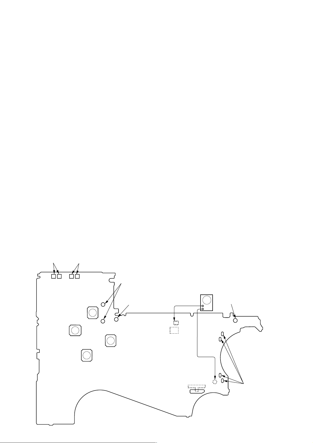
– MAIN Board (side B) –
TAPE DETECT
(S901-1)
(S901-2)
– REW
(S5)
ATS
+ FF
(S4)
x
RADIO OFF
(S3)
Y
REPEAT
(S9)
connect to the plunger
(PM901)
battery
terminal #
square wave
(sine wave)
10 Hz, – 3.5 dB
Q15
PH1
DIRECTION
FWDTSTOPtREV
AF oscillator
S1
+
–
(GND)
TP23
battery
terminal 3
connect to the
motor (M601)
3
WM-FX888
y
y
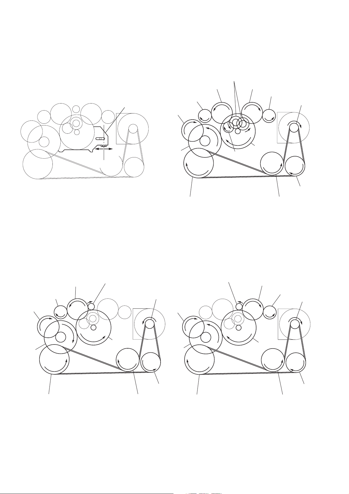
Slider (NR) Rotation system
Rotation system during PLAY.
idler gear (A) (side T)
gear (REEL) (side T)
slider (NR)
cam gear
gear (NR)
(FWD : left side/
REV : right side)
idler gear (A) (side S)
gear (REEL) (side S)
motor pulley
side F
side R
center
gear (Y)
insert flywheel (N) insert flywheel (R)
idler gear (B)
Rotation system during FF. Rotation system during REW.
gear (FR)
(REW: right side)
idler gear (A) (side T)
gear (REEL) (side T)
cam gear
gear (FR)
(FF: left side)
motor pulley
cam gear
clutch assy (F)
idler gear (A)
(side S)
reverse pulley
gear (REEL)
(side S)
motor pulle
clutch assy (F)
gear (Y)
insert flywheel (N) insert flywheel (R)
4
gear (Y)
reverse pulle
clutch assy (F)
reverse pulley
insert flywheel (N) insert flywheel (R)
SECTION 2
GENERAL
WM-FX888
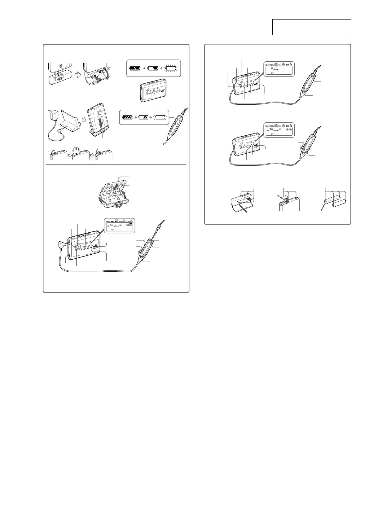
This section is extracted from
instruction manual.
A
B
D
REW (AMS)
FF (AMS)
Y•REPEAT**
CHARGE
C
FWD (forward) side
REV (reverse) side
Plug in firmly.
E
F
G
TUNE/PRESET –
RADIO OFF
TUNE/PRESET +
BAND•
RADIO ON
ENTER
SETMENU
HOLD
HOLD
SET
MENU
Terminals Terminals Terminals
RADIO ON/
BAND•OFF
SOUND
MODE
+
–
i
VOL*
* There is a tactile dot beside VOL on the main unit to show the direction to turn up the volume.
**The button has a tactile dot.
MENU SET
x
HOLD
HOLD
VOL
FF
REW
Y•x**
5
WM-FX888
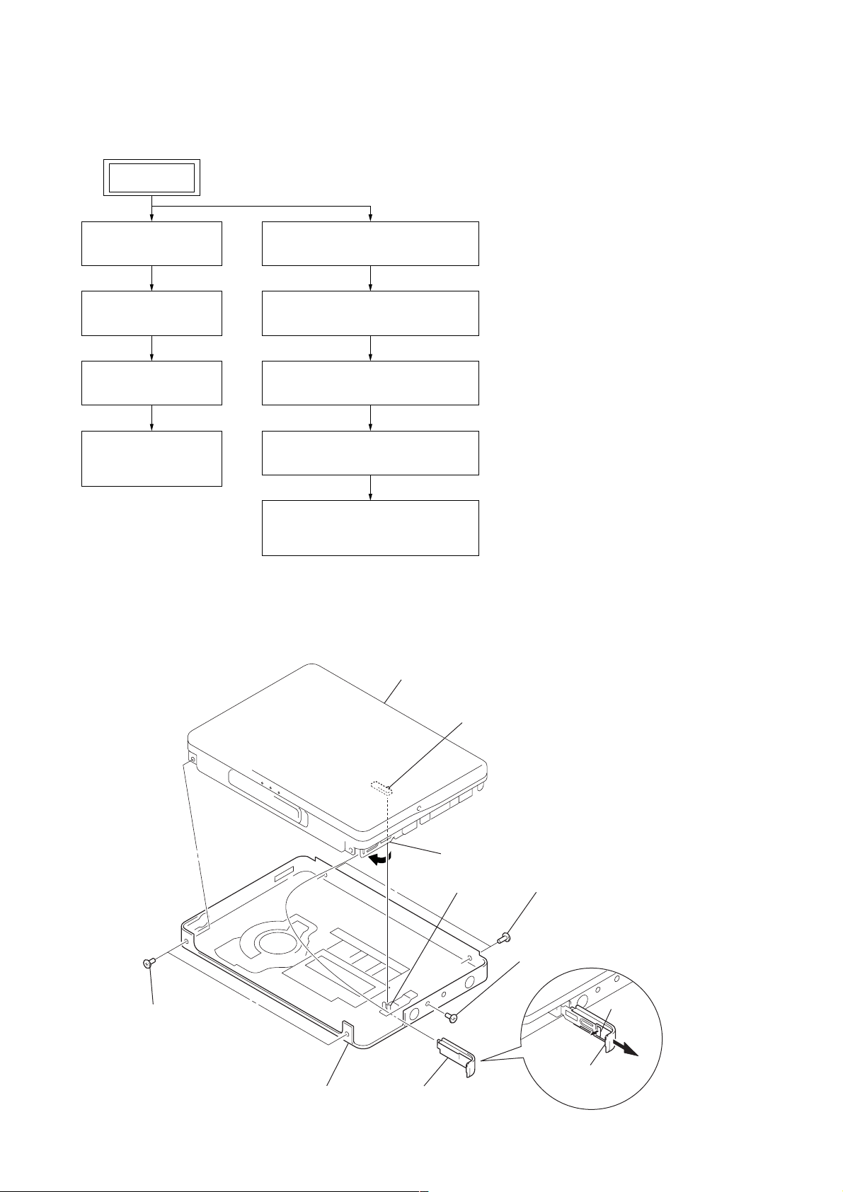
• This set can be disassembled in the order shown below.
3-1. DISASSEMBLY FLOW
set
SECTION 3
DISASSEMBLY
3-2. CASE SECTION
(page 6)
3-3. MAIN BOARD
(page 7)
3-4. BELT (F2)
(page 7)
3-5. MOTOR
(CAPSTAN/REEL)
(page 8)
Note: Follow the disassembly procedure in the numerical order given.
3-6. CASSETTE LID SUB ASSY
(page 8)
3-7. REEL ORNAMENT BLOCK ASSY
(page 9)
3-8. HOLDER (F) ASSY (/M)
(page 9)
3-9. PINCH LEVER (RA)/(NA) ASSY
(page 10)
3-10.MAGNETIC HEAD
(PLAYBACK) (HP901)
(page 10)
3-2. CASE SECTION
5
two screws (M1.4)
cassette lid assy
4
Close terminal board assy.
lever (hold)
S2
Note: On installation
cassette lid assy adjust
the S2 and lever (hold).
5
two screws (M1.4)
6
screw (M1.4)
2
claw
1
open battery lid.
3
7
case section
battery lid
6
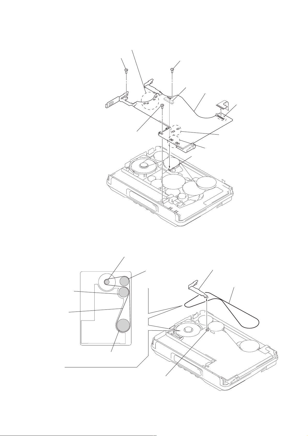
3-3. MAIN BOARD
1
2
screw (1.7 × 3)
2
Remove four solders of motor (M601).
screw (1.7 × 3)
2
screw (M1.4) (toothed lock)
S2
3
MAIN board
1
Remove four solders of
slider
leaf switch (S901).
1
Remove six solders of
head flexible board.
1
Remove two solders of
plunger solenoid (PM901).
WM-FX888
Note: On installation
MAIN board adjust
the S2 and slider.
3-4. BELT (F2)
insert
flywheel (R)
belt (F2)
motor pulley
reverse pulley
2
battery terminal board
3
belt (F2)
insert flywheel (N)
1
Remove solder of
battery terminal board.
7
WM-FX888
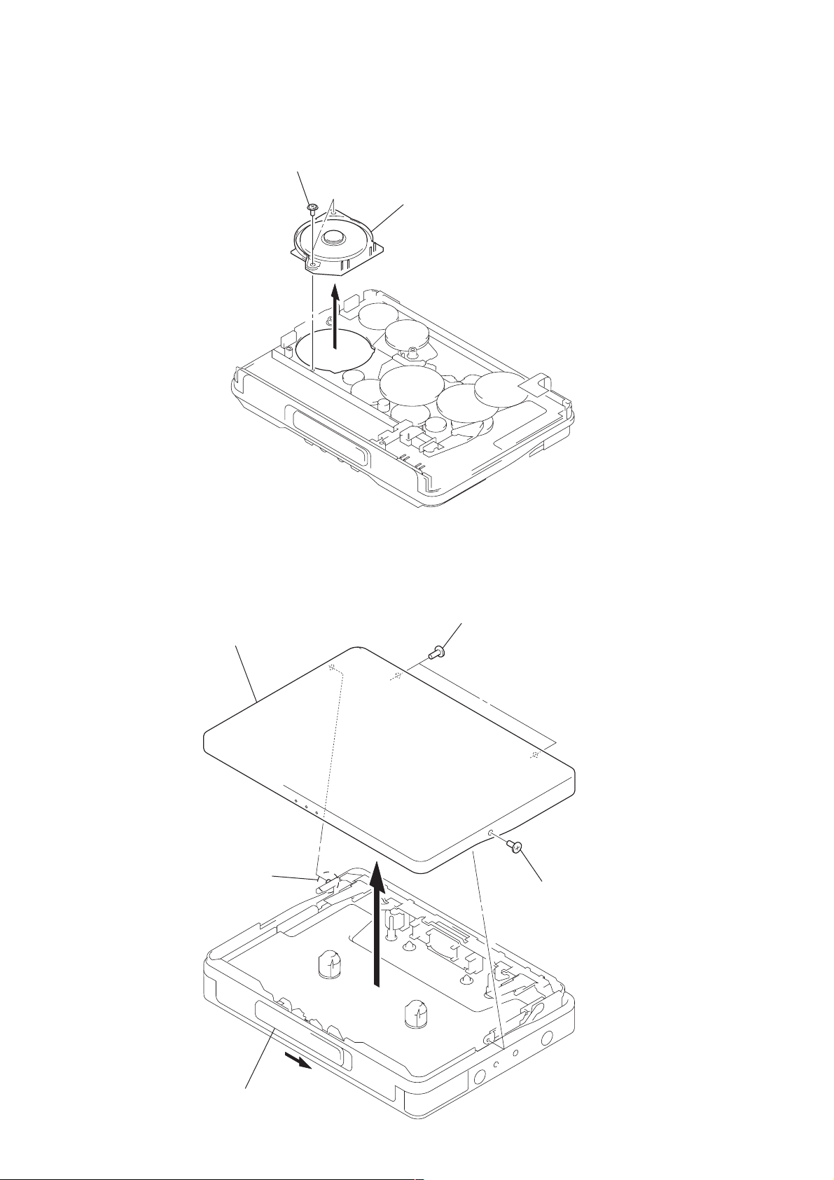
3-5. MOTOR (CAPSTAN/REEL) (M601)
1
two screws (M1.4)
2
motor (capstan/reel) (M601)
3-6. CASSETTE LID SUB ASSY
4
cassette lid sub assy
3
boss
2
two screws (M1.4)
2
screw (M1.4)
1
Open knob (open).
8
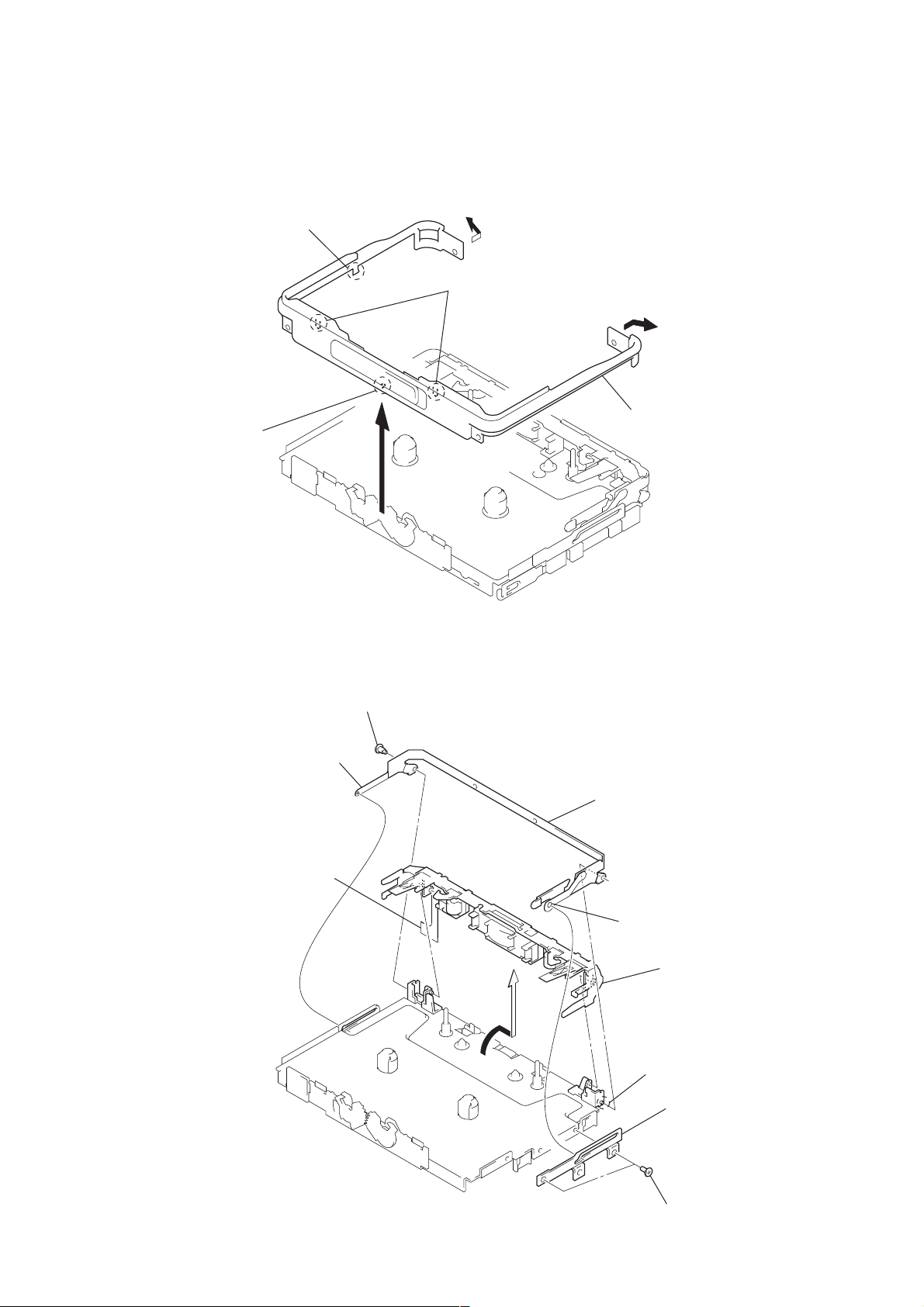
3-7. REEL ORNAMENT BLOCK ASSY
WM-FX888
2
claw
3
boss
3-8. HOLDER (F) ASSY (/M)
4
two claws
1
1
5
reel ornament block assy
5
lock lever (S) (/M)
8
Remove six solders of
head flexible board.
4
screws (M1.4)
7
bracket (cassette) assy (/M)
2
boss
9
holder (F) assy (/M)
6
boss
3
lock lever (B) (/M)
1
two screws (IB lock)
9
WM-FX888
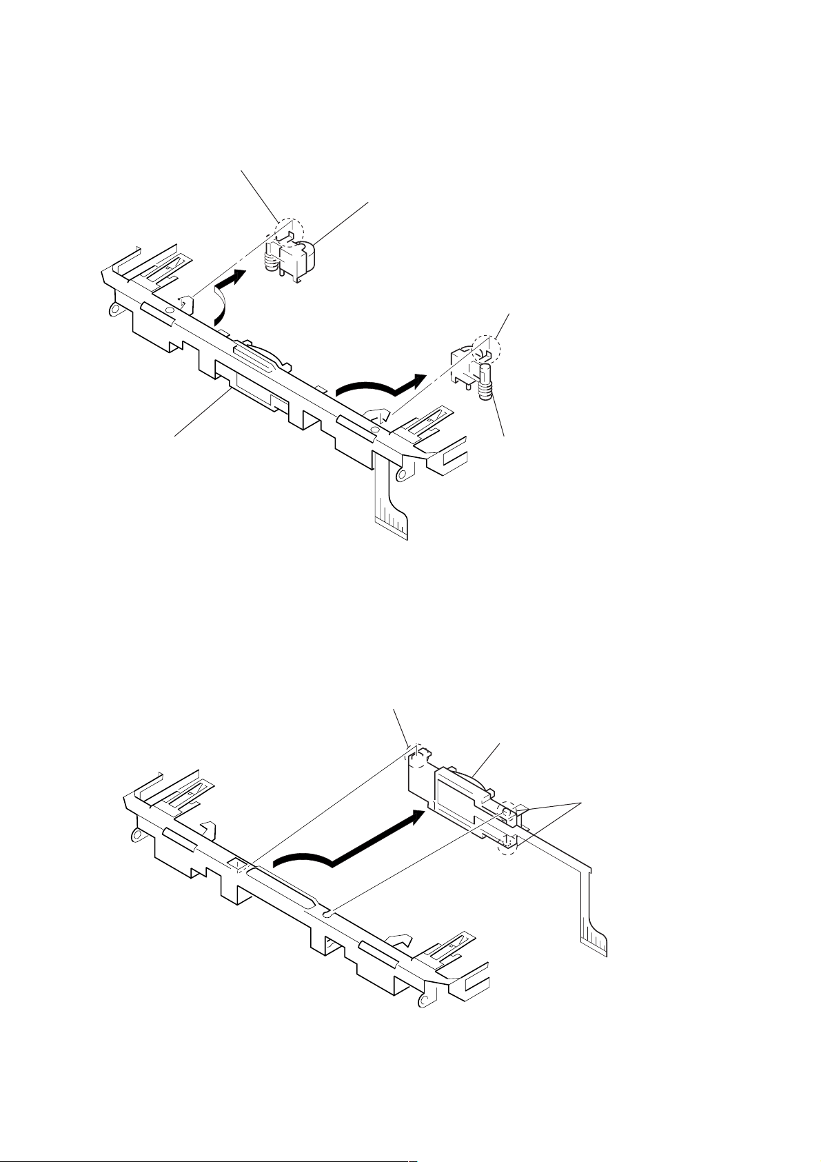
3-9. PINCH LEVER (RA)/(NA) ASSY
1
claw
2
Remove pinch lever (RA) assy
in the direction of the arrow.
3
claw
holder (F) assy/M
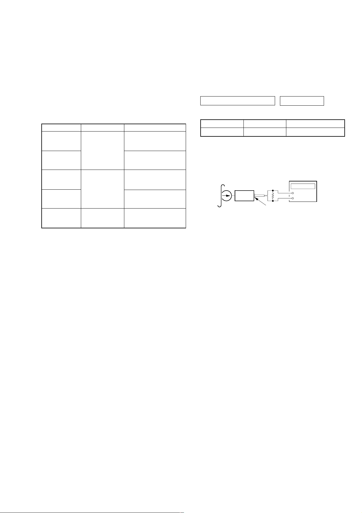
3-10. MAGNETIC HEAD (PLAYBACK) (HP901)
1
claw
2
4
Remove pinch lever (NA) assy
in the direction of the arrow.
magnetic head (playback)
4
(HP901)
3
claw
10
SECTION 4
r
MECHANICAL ADJUSTMENTS
WM-FX888
SECTION 5
ELECTRICAL ADJUSTMENTS
PRECAUTION
1. Clean the following parts with a denatured-alcohol-moistened
swab:
playback head pinch roller
rubber belts capstan
2. Demagnetize the playback head with a head demagnetizer.
(Do not bring the head demagnetizer close to the erase head.)
3. Do not use a magnetized screwdriver for the adjustments.
4. The adjustments should be performed with the rated power
supply voltage (1.3 V) unless otherwise noted.
Torque Measurement
Mode Torque Meter Meter Reading
FWD 15 – 25 g•cm
CQ-102C
FWD
Back Tension
REV 15 – 25 g•cm
CQ-102RC
REV
Back Tension
FF, REW CQ-201B more than 35 g•cm
(1.47 – 2.94 mN•m)
(0.22 – 0.36 oz•inch)
(0.029 – 0.196 mN•m)
0.3 – 2.0 g•cm
(0.004 – 0.01 oz•inch)
(1.47 – 2.94 mN•m)
(0.22 – 0.36 oz•inch)
(0.029 – 0.196 mN•m)
0.3 – 2.0 g•cm
(0.004 – 0.01 oz•inch)
(more than 3.43 mN•m)
(more than 0.5 oz•inch)
PRECAUTION
1. Specified voltage : 1.3 V (DC)
2. Setting
SOUND RV/MB/GRV : OFF
AVLS : OFF
;NR : OFF
BL SKIP : OFF
TAPE DECK SECTION 0 dB=0.775 V
Test tape
Type Signal Used for
WS-48A 3 kHz, 0 dB Tape Speed Adjustment
Tape Speed Adjustment
Setting:
Function: TAPE
Test tape
WS-48A
(3 kHz, 0 dB)
set
Procedure:
1. Playback WS-48A (tape center) in the FWD state.
2. Adjsut RV601 so tha t the frequenc y counter reading becomes
3,000 Hz.
frequency counte
16 Ω
+
–
i jack (J701)
Specification Values: 2,970 to 3,030 Hz
3. Playback WS-48A (tape center) in the REV state.
Check that the frequency counter reading is within 2%
(approx.60 Hz) of the reading of step 1.
Adjustment Location: MAIN BOARD (See page 12)
11
 Loading...