

Sony WMFX-663 Service manual
WM-FX661/FX663/FX665
SERVICE MANUAL
Ver 1.1 2002. 01
Photo : WM-FX661
AEP Model
WM-FX661/FX663/FX665
E Model
Chinese Model
WM-FX663/FX665
UK Model
Australian Model
WM-FX665
Canadian Model
WN-FX663
9-924-908-12
2002A1600-1
© 2002.1
RADIO CASSETTE PLAYER
Sony Corporation
Personal Audio Company
Published by Sony Engineering Corporation

TABLE OF CONTENTS
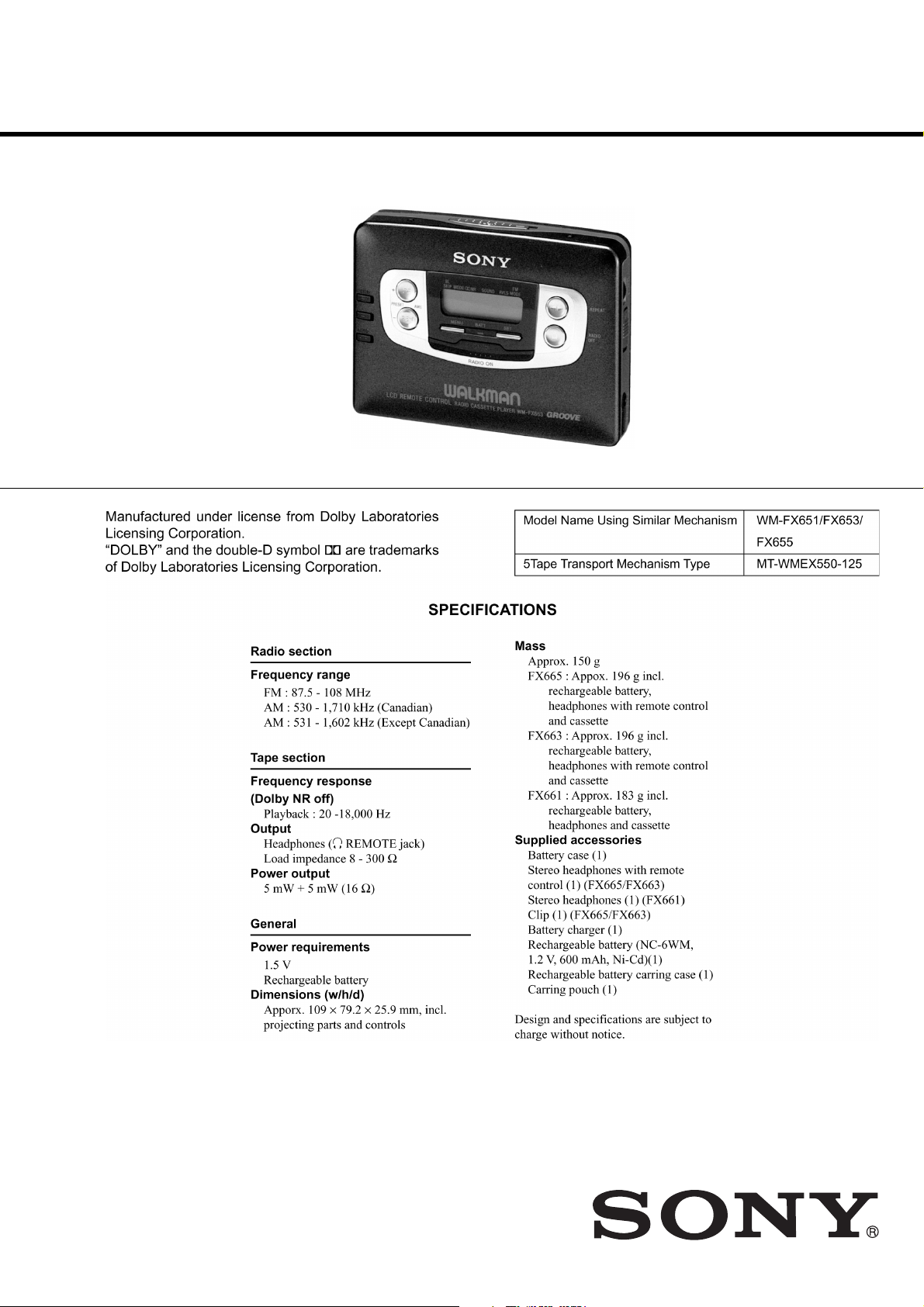
Specification ················································································· 1
1. GENERAL ·········································································· 3
2. SERVICE NOTE ······························································· 3
3. DISASSEMBLY
3-1. Case Assy Removal ······················································· 4
3-2. Tuner Board Removal ··················································· 4
3-3. Audio Board Removal··················································· 5
3-4. Cassette Lid Assy Removal ··········································· 5
3-5. Mechanism Deck Removal ··········································· 6
4. MECHANICAL ADJUSTMENT ·································· 7
5. ELECTRICAL ADJUSTMENT ···································· 7
6. DIAGRAMS········································································ 9
6-1. Block Diagram ······························································ 9
6-2. IC Pin Function Description········································ 11
6-3. Printed Wiring Boards (Tuner Section) ······················· 13
6-4. Schematic Diagram (Tuner Section) ··························· 17
6-5. Schematic Diagram (Audio Section)···························20
6-6. Printed Wiring Board (Audio Section) ························ 23
SAFETY-RELATED COMPONENT WARNING!!
COMPONENTS IDENTIFIED BY MARK ! OR DOTTED LINE WITH
MARK ! ON THE SCHEMATIC DIAGRAMS AND IN THE PARTS
LIST ARE CRITICAL TO SAFE OPERATION. REPLACE THESE
COMPONENTS WITH SONY PARTS WHOSE PART NUMBERS
APPEAR AS SHOWN IN THIS MANUAL OR IN SUPPLEMENTS
PUBLISHED BY SONY.
ATTENTION AU COMPOSANT AYANT RAPPORT
À LA SÉCURITÉ!
LES COMPOSANTS IDENTIFÉS PAR UNE MARQUE ! SUR LES
DIAGRAMMES SCHÉMATIQUES ET LA LISTE DES PIÈCES SONT
CRITIQUES POUR LA SÉCURITÉ DE FONCTIONNEMENT. NE
REMPLACER CES COMPOSANTS QUE PAR DES PIÈSES SONY
DONT LES NUMÉROS SONT DONNÉS DANS CE MANUEL OU
DANS LES SUPPÉMENTS PUBLIÉS PAR SONY.
7. EXPLODED VIEWS
7-1. Cabinet Section ··························································· 29
7-2. Audio, Tuner Board Section ········································ 30
7-3. Mechanism Section (MT-WMEX550-125) ·················31
8. ELECTRICAL PARTS LIST ······································· 32
Flexible Circuit Board Repairing
• Keep the temperature of the soldering iron aroud 270˚ C during
repairing.
• Do not touch the soldering iron on the same conductor of the
circuit board (within 3 times).
• Be careful not to apply force on the conductor when soldering
or unsoldering.
Notes on chip component replacement
• Never reuse a disconnected chip component.
• Notice that the minus side of a tantalum capacitor may be
damaged by heat.
— 2 —
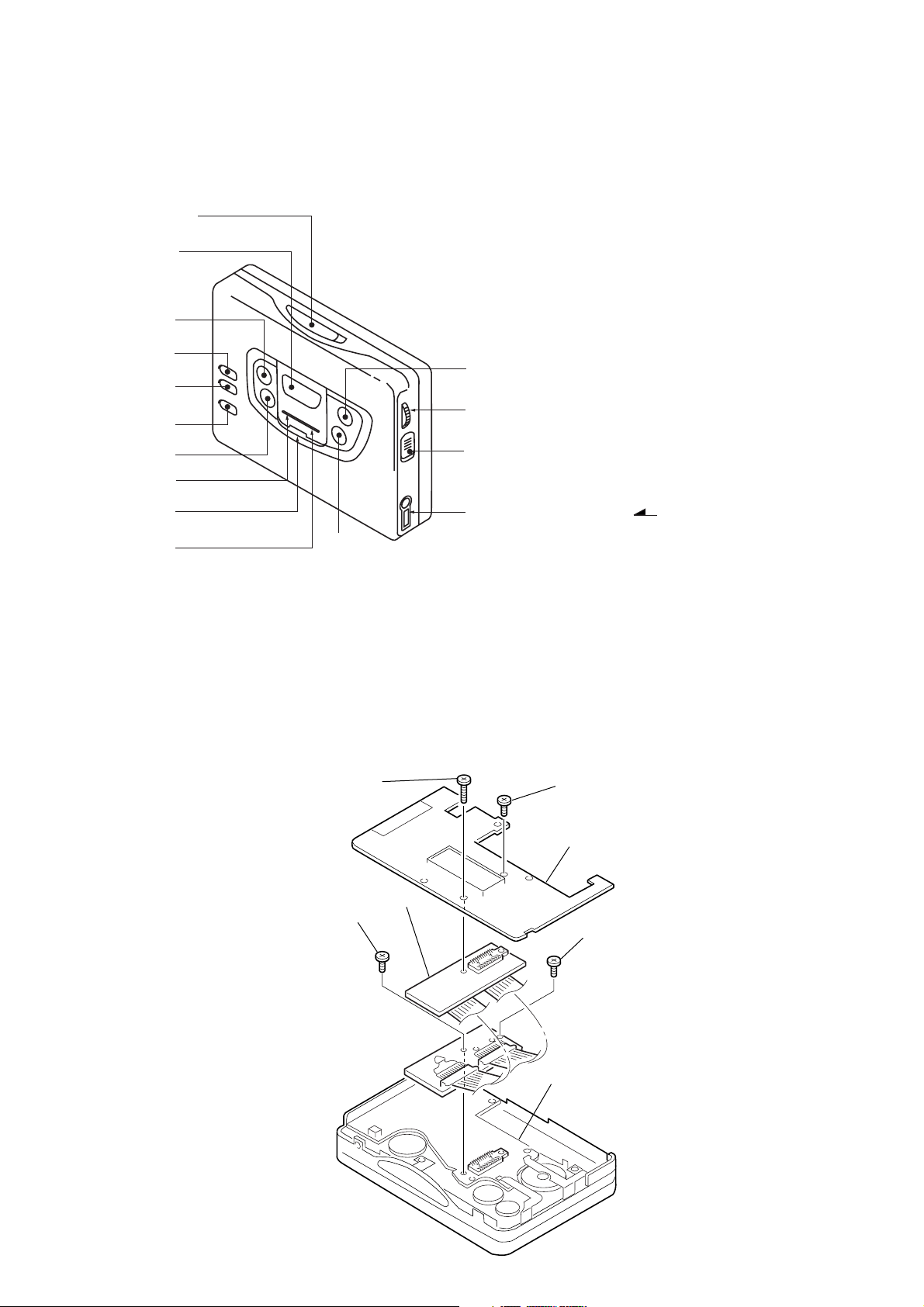
• LOCATION OF CONTROL
SECTION 1
GENERAL
1 OPEN knob
2 PRESET + /AMS FF button
2
4
5
6
3
!
0
!¢
9
1
3 PRESET – /AMS REW button
4 TUNING + button
5 TUNING – button
6 ENTER button
7 ˇ /REPEAT button
7
!`
!“
8 p /RADIO OFF button
9 MENU button
0 SET button
!` VOLUME knob
!£
8
!“ HOLD knob
2 REMOTE jack
!£
!¢ Display window
! BAND button
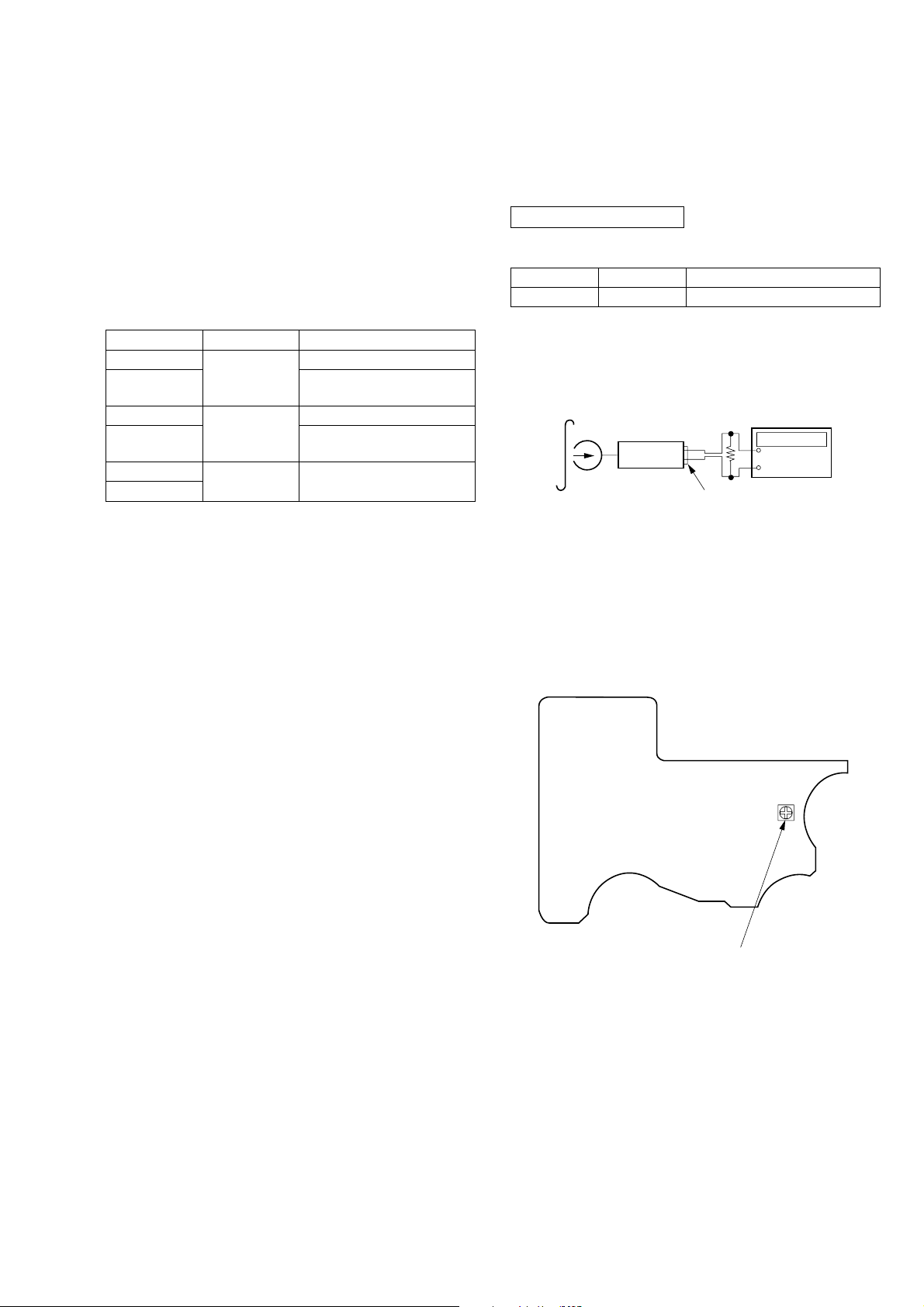
SECTION 2
SERVICE NOTE
• Regarding the method of adjustment and voltage check, perform sections 3-1 and 3-2 of the DISASSEMBLY, and attach the JIG (extension
cable) to the AUDIO board as shown below.
JIG Part No. : J-2503-005-A
Screw
(M1.4 × 5.0)
Screw
(M1.4 × 5.0)
JIG
Screw (M1.4 × 5.0)
TUNER board
Screw (M1.7 × 4.0)
AUDIO board
— 3 —
SECTION 3
)
DISASSEMBLY
Note : Disassemble the unit in the order as shown below.
CASE ASSYSET
TUNER BOARD
CASSETTE LID ASSY
AUDIO BOARD
MECHANISM DECK
Note : Follow the disassembly procedure in the numerical order given.
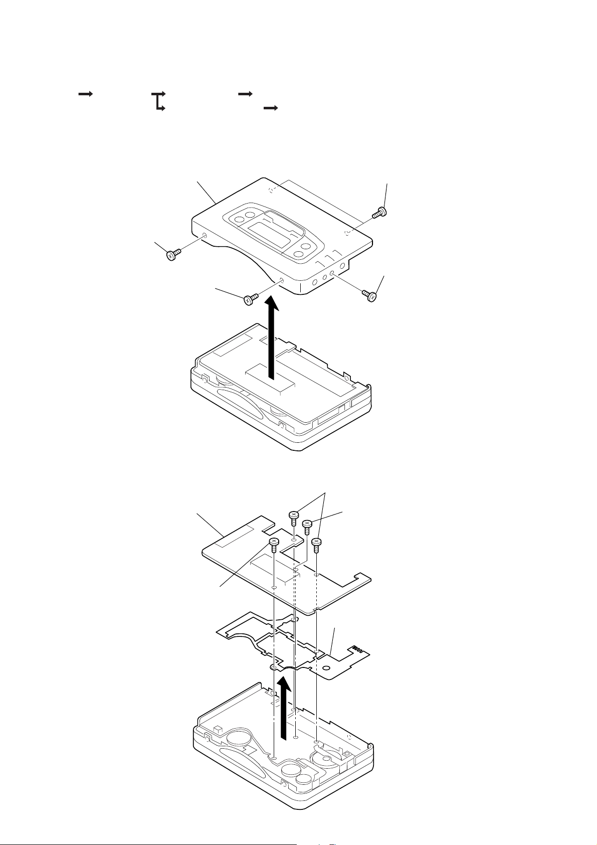
3-1. CASE ASSY REMOVAL
6 Case assy
2 Screw
(M1.4 × 2.2)
1 Screw
(M1.4 × 3)
5
4 Screws
(M1.4 × 2.2)
3 Screw
(M1.4 × 2.2
3-2. TUNER BOARD REMOVAL
4 TUNER board
1 Screws (M1.7 × 6)
2 Screw (M1.7 × 3)
3 Screw
(M1.4 × 4.5)
6 GUIDE (TU)
5
— 4 —
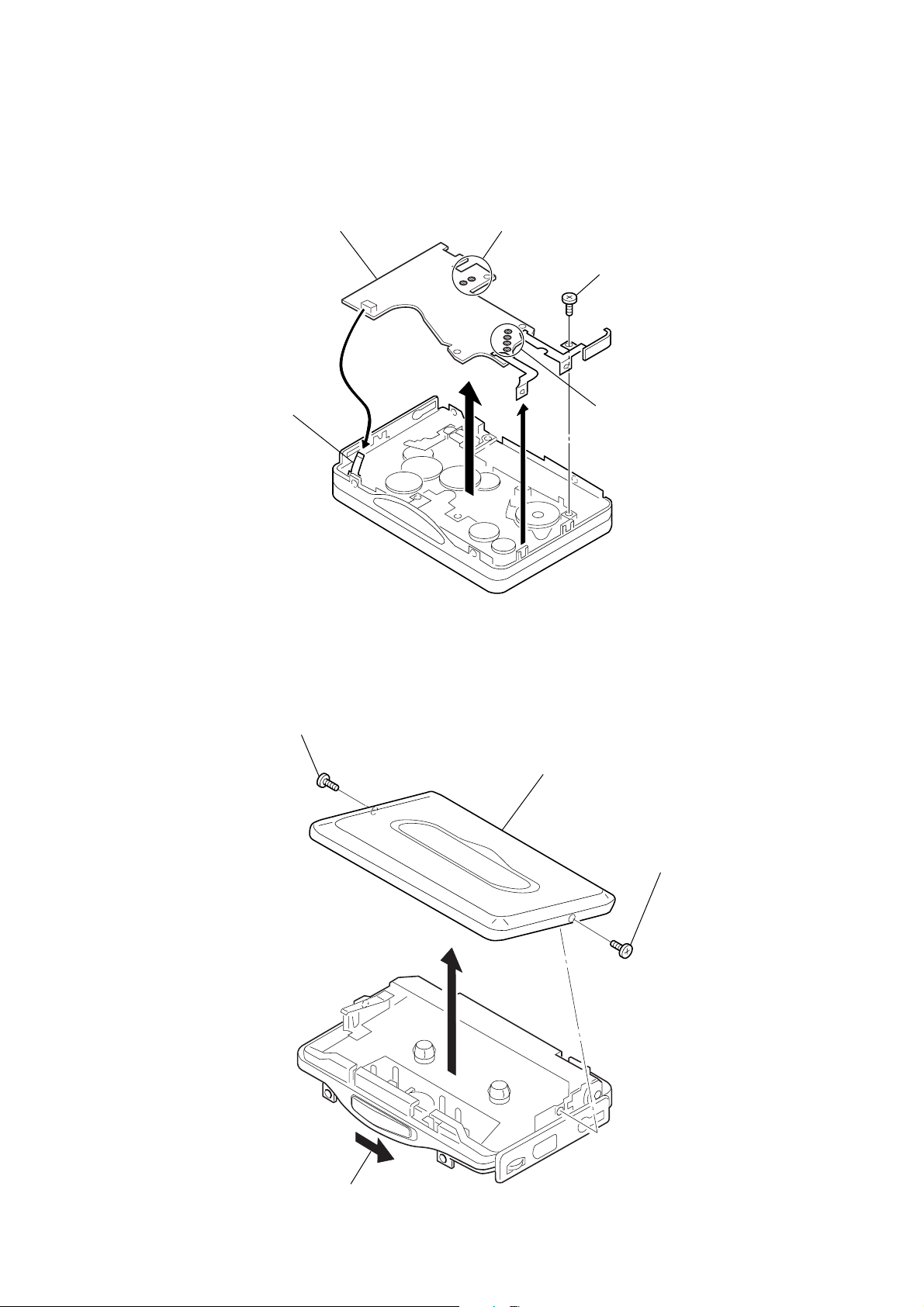
3-3. AUDIO BOARD REMOVAL
7 AUDIO board
4 Flexible board
2 Remove solder
1 Screw (M1.7 × 3)
6
3 Remove solder
5
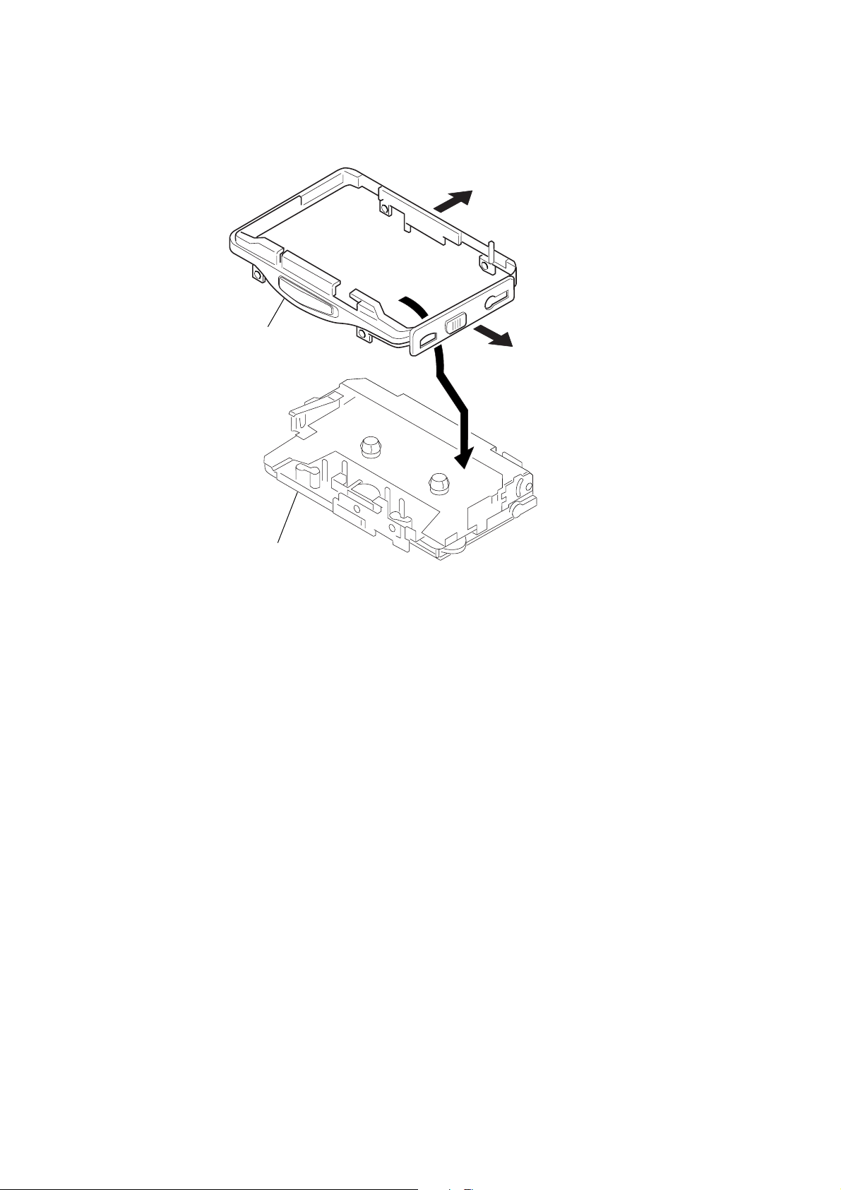
3-4. CASSETTE LID ASSY REMOVAL
2 Screw (M1.4 × 2)
5 Cassette lid assy
3 Screw (M1.4 × 2)
4
1 OPEN button
— 5 —
3-5. MECHANISM DECK REMOVAL
2
4 Reel ornament
5 Mechanism deck
1
3
— 6 —
SECTION 4
r
MECHANICAL ADJUSTMENT
SECTION 5
ELECTRICAL ADJUSTMENT
PRECAUTION
1. Clean the following parts with a denatured-alcahol-moistened
sweb :
Playback head Pinch roller
Rubber belt Capstan
2. Demagnetize the playback head using a demagnetizer.
3. Do not use a magnetized screwdriver for adjustments.
4. After adjusting, apply screw-locking compound onto the
adjusted parts.
5. Unless specified otherwise, use a specified voltage (1.3V) to
perform the adjustments.
Torqu Measurement
Mode
FWD
FWD
Back Tension
REV
REV
Back Tension
FF
REW
Torqu meter
CQ-102C
CQ-102RC
CQ-201B
Meter reading
20 to 30 g · cm
0.4 to 2.0 g · cm
20 to 30 g · cm
0.4 to 2.0 g · cm
More than 40 g · cm
PRECAUTION
1. Specified voltage : 1.3V
2. Switch position
DOLBY NR switch : OFF
AVLS switch : OFF
CASSETTE SECTION
Test Tape
Type
WS-48A
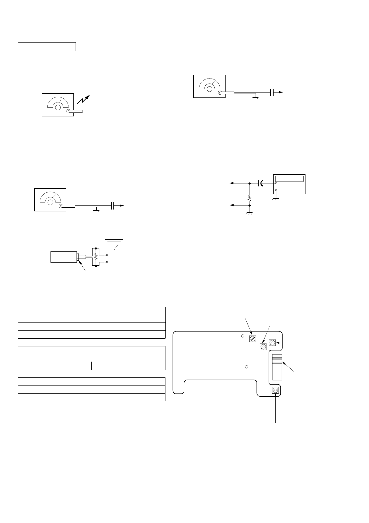
Tape Speed Adjustmnet
Procedure :
Test tape
WS-48A
(3kHz, 0dB)
1. Playback WS-48A (Tape center part) in the FWD state and
adjust RV601 so that the frequency counter reading becomes
2,970Hz to 3030Hz.
2. Playback WS-48A (Tape center) in the REV state.
Check that frequency counter reading is within 60Hz of the
reading of step1.
Signal
3kHz, 0dB
Set
Purpose
Tape Speed Adjustment
Frequency counte
16Ω
+
–
PHONES jack
Adjustment Point :
[MAIN BOARD] — SIDE A —
RV601 : Tape speed
— 7 —
TUNER SECTION
)
)
[AM]
BAND switch : AM
FM VCO Adjustment
Procedure :
FM RF signal
generator
AM RF signal
generator
30% amplitude modulation
by 400Hz signal.
Output level : as low as possible
[FM]
BAND switch : FM
FM RF signal
generator
22.5kHz frequency
deviation by 400Hz signal.
Output level : as low as possible.
Set
Put the lead-wire antenna
close to the set.
0.01µF
to ANT (TP1
Level meter
32Ω
+
–
0.01µF
to ANT (TP1
Carrier frequency : 98MHz
Modulation : No moduration
Output level : 0.1V (100dB)
1. Connect the frequency counter to the positions shown below.
2. Turn the set to 98MHz.
3. Adjust RV1 for 18,900 to 19,100 Hz reading on the frequency
counter.
Frequency counter
TP23
(IC7 pin !™)
IC7 pin 9
1µF
+
–
100Ω
PHONES
• Repeat the procedures in each adjustment several times, and the
frequency coverage and tracking adjustments should be finally
done by the trimmer capacitors.
AM TRACKING ADJUSTMENT
Adjust for a maximum reading on level meter.
L4 621kHz
CT1 1,395kHz
FM IF ADJUSTMENT
Adjust for a maximum reading on level meter.
L3 10.7MHz
FM VOLTAGE ADJUSTMENT
1.05V to 1.15V (3.55 to 3.65V)
L2 76MHz (87.5MHz)
( ) : Saudi Arabia model
Adjustment Parts Location :
[TUNER BOARD] — SIDE A —
L2 : FM
Voltage Adjustment
TP1
TP13
RV1 : FM VCO Adjustment
L3 : FM IF Adjustment
CT1 : AM Tracking
Adjustment
L4 : AM Tracking
Adjustment
— 8 —
 Loading...