

Sony WMFX-655 Service manual
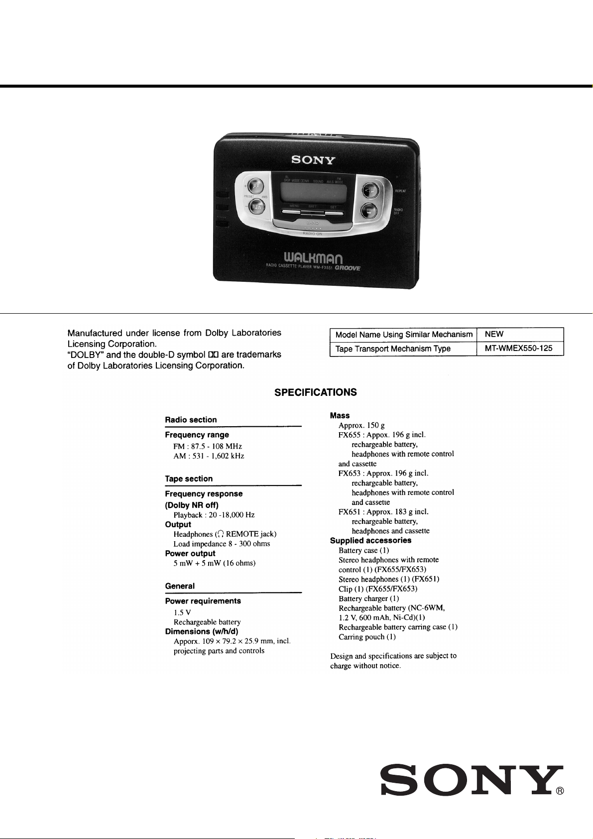
WM-FX651/FX653/FX655
SERVICE MANUAL
Ver 1.1 2002. 01
Photo : WM-FX651
AEP Model
WM-FX651/FX653/FX655
E Model
WM-FX653/FX655
Australian Model
Tourist Model
WM-FX655
Canadian Model
WN-FX653
9-923-157-12
2002A1600-1
© 2002.1
RADIO CASSETTE PLAYER
Sony Corporation
Personal Audio Company
Published by Sony Engineering Corporation

TABLE OF CONTENTS
Specification ················································································· 1
1. GENERAL ·········································································· 3
2. SERVICE NOTE ······························································· 3
3. DISASSEMBLY
3-1. Case Assy Removal ······················································· 4
3-2. Tuner Board Removal ··················································· 4
3-3. Audio Board Removal··················································· 5
3-4. Cassette Lid Assy Removal ··········································· 5
3-5. Mechanism Deck Removal ··········································· 6
4. MECHANICAL ADJUSTMENT ·································· 7
5. ELECTRICAL ADJUSTMENT ···································· 7
6. EXPLANATION OF IC TERMINALS························· 9
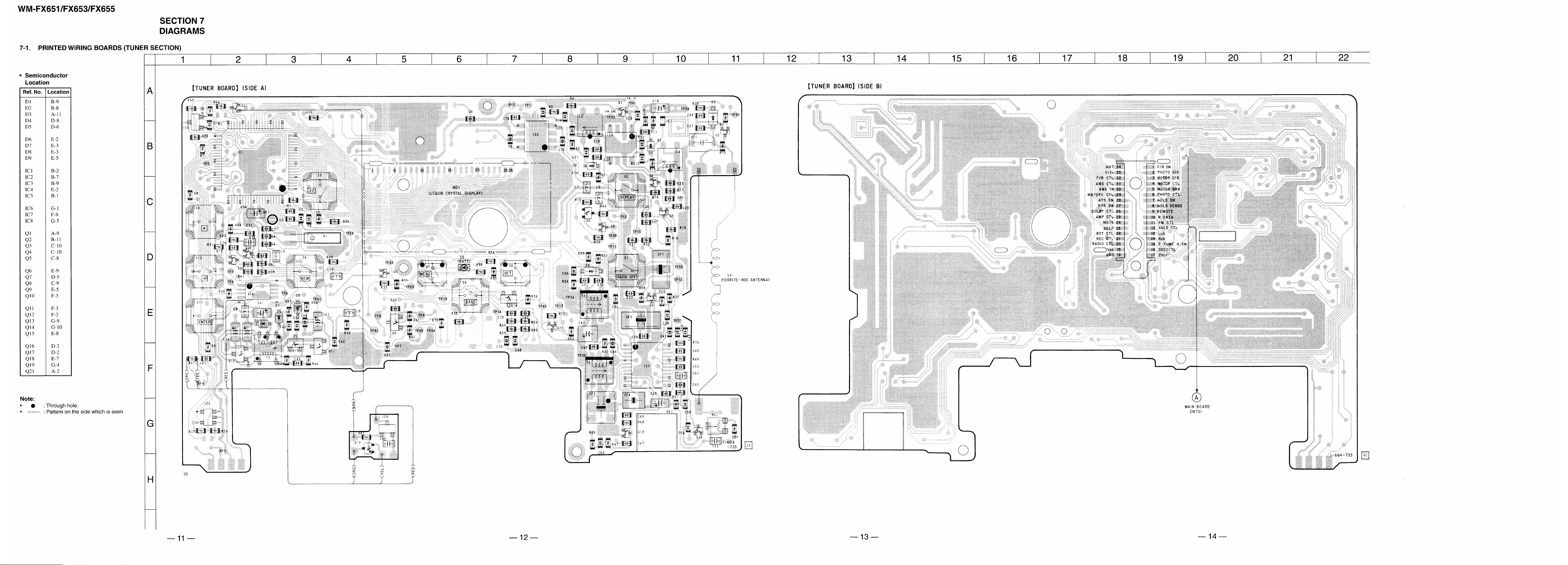
7. DIAGRAMS
7-1. Printed Wiring Boards (Tuner Section) ······················· 11
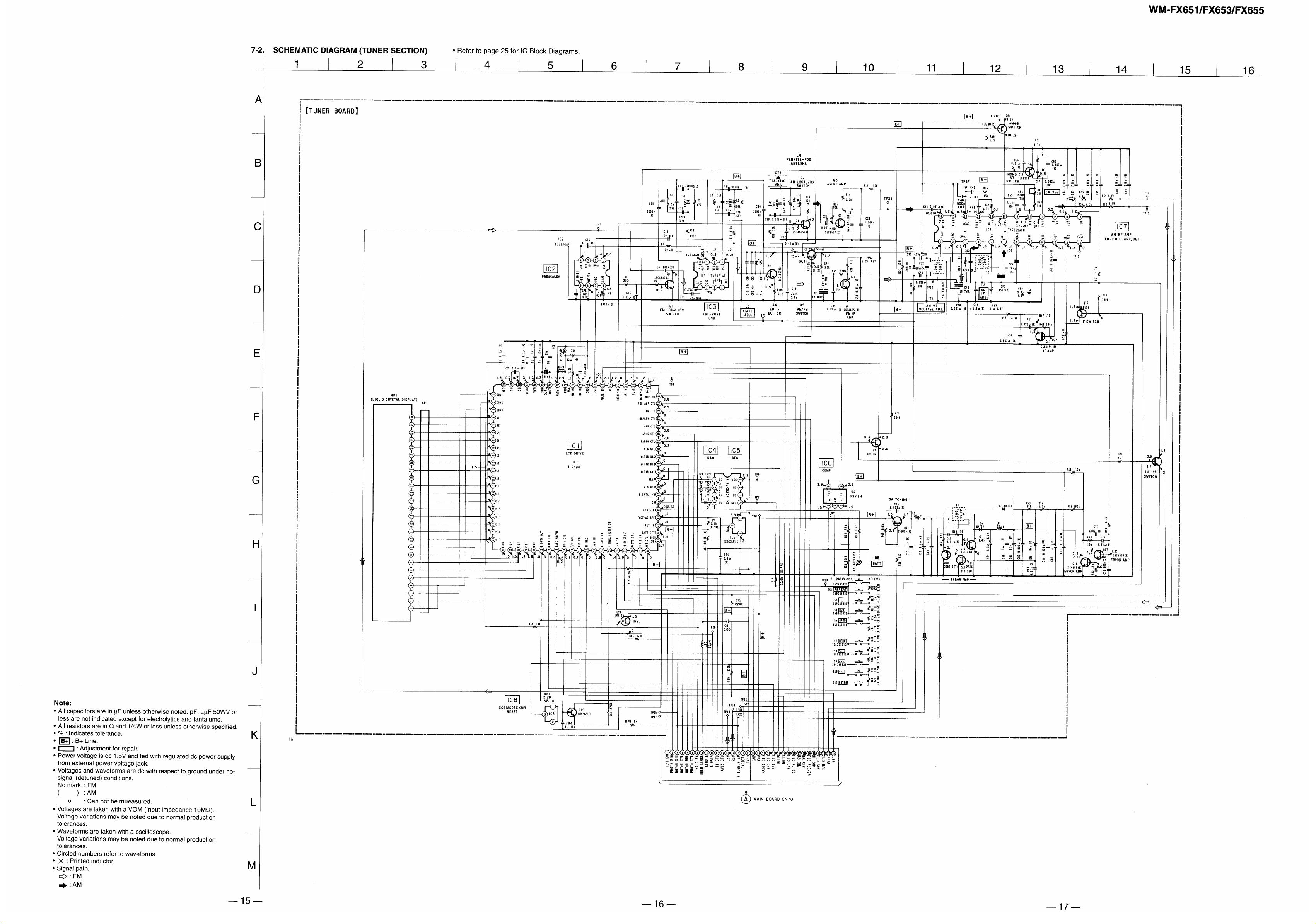
7-2. Schematic Diagram (Tuner Section) ··························· 15
7-3. Schematic Diagram (Audio Section)···························18
7-4. Printed Wiring Board (Audio Section) ························ 21
8. EXPLODED VIEWS
8-1. Cabinet Section ··························································· 27
8-2. Audio, Tuner Board Section ········································ 28
8-3. Mechanism Section (MT-WMEX550-125) ················· 29
9. ELECTRICAL PARTS LIST ······································· 30
— 2 —
Flexible Circuit Board Repairing
• Keep the temperature of the soldering iron aroud 270˚ C during
repairing.
• Do not touch the soldering iron on the same conductor of the
circuit board (within 3 times).
• Be careful not to apply force on the conductor when soldering
or unsoldering.
Notes on chip component replacement
• Never reuse a disconnected chip component.
• Notice that the minus side of a tantalum capacitor may be
damaged by heat.
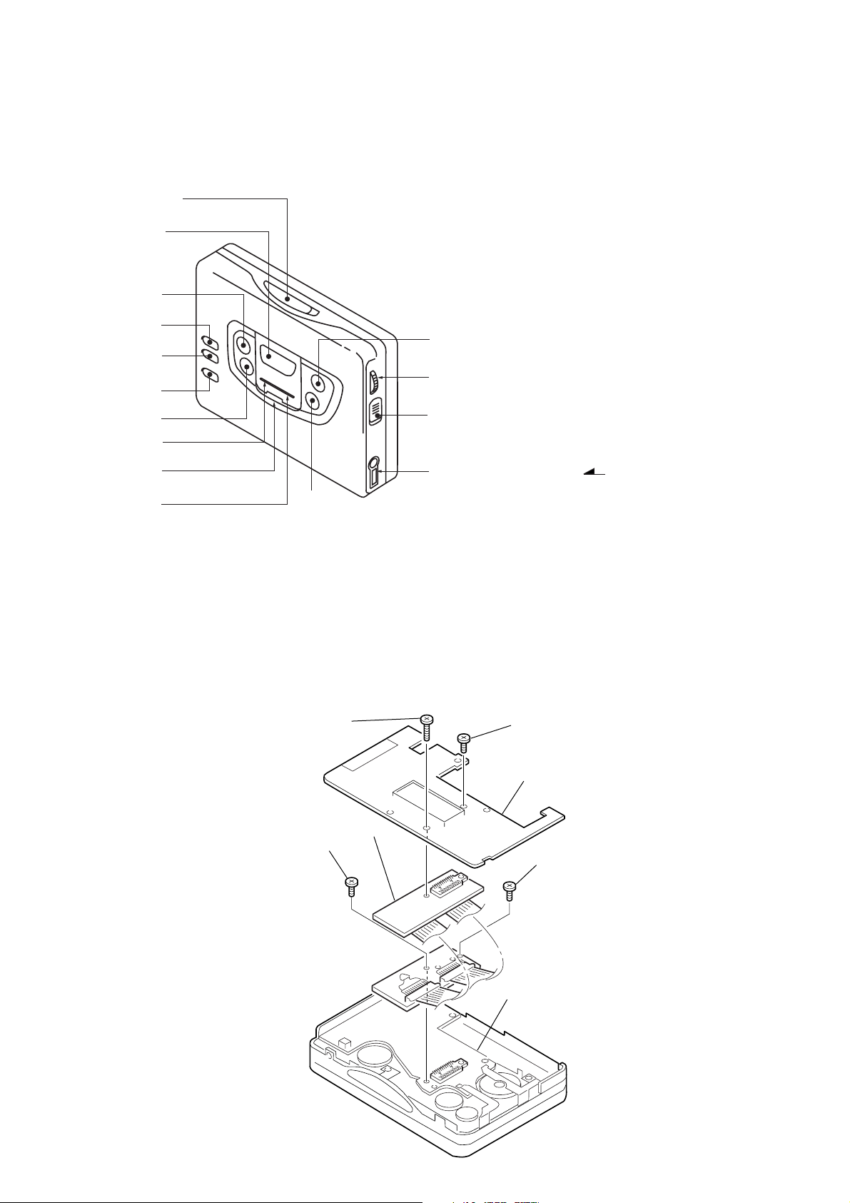
• LOCATION OF CONTROL
SECTION 1
GENERAL
1 OPEN knob
2 PRESET + /AMS FF button
4
5
6
3
0
2
9
!
!¢
1
3 PRESET – /AMS REW button
4 TUNING + button
5 TUNING – button
6 ENTER button
7 ˇ /REPEAT button
7
!`
!“
8 p /RADIO OFF button
9 MENU button
0 SET button
!` VOLUME knob
!£
8
!“ HOLD knob
2 REMOTE jack
!£
!¢ Display window
! BAND button
SECTION 2
SERVICE NOTE
• Regarding the method of adjustment and voltage check, perform sections 3-1 and 3-2 of the DISASSEMBLY, and attach the JIG to the
AUDIO board as shown below.
Screw
(M1.4 × 5.0)
Screw
(M1.4 × 5.0)
JIG
Screw (M1.4 × 5.0)
TUNER board
Screw (M1.7 × 4.0)
AUDIO board
— 3 —
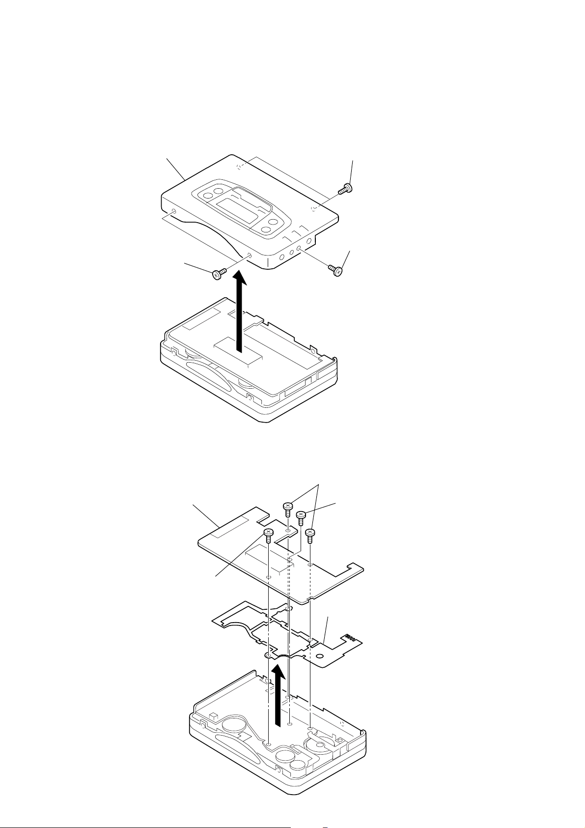
SECTION 3
)
DISASSEMBLY
Note : Follow the disassembly procedure in the numerical order given.
3-1. CASE ASSY REMOVAL
5 Case assy
1 Screw
(M1.4 × 2.2)
3 Screw
(M1.4 × 2.2)
2 Screw
(M1.4 × 2.2
4
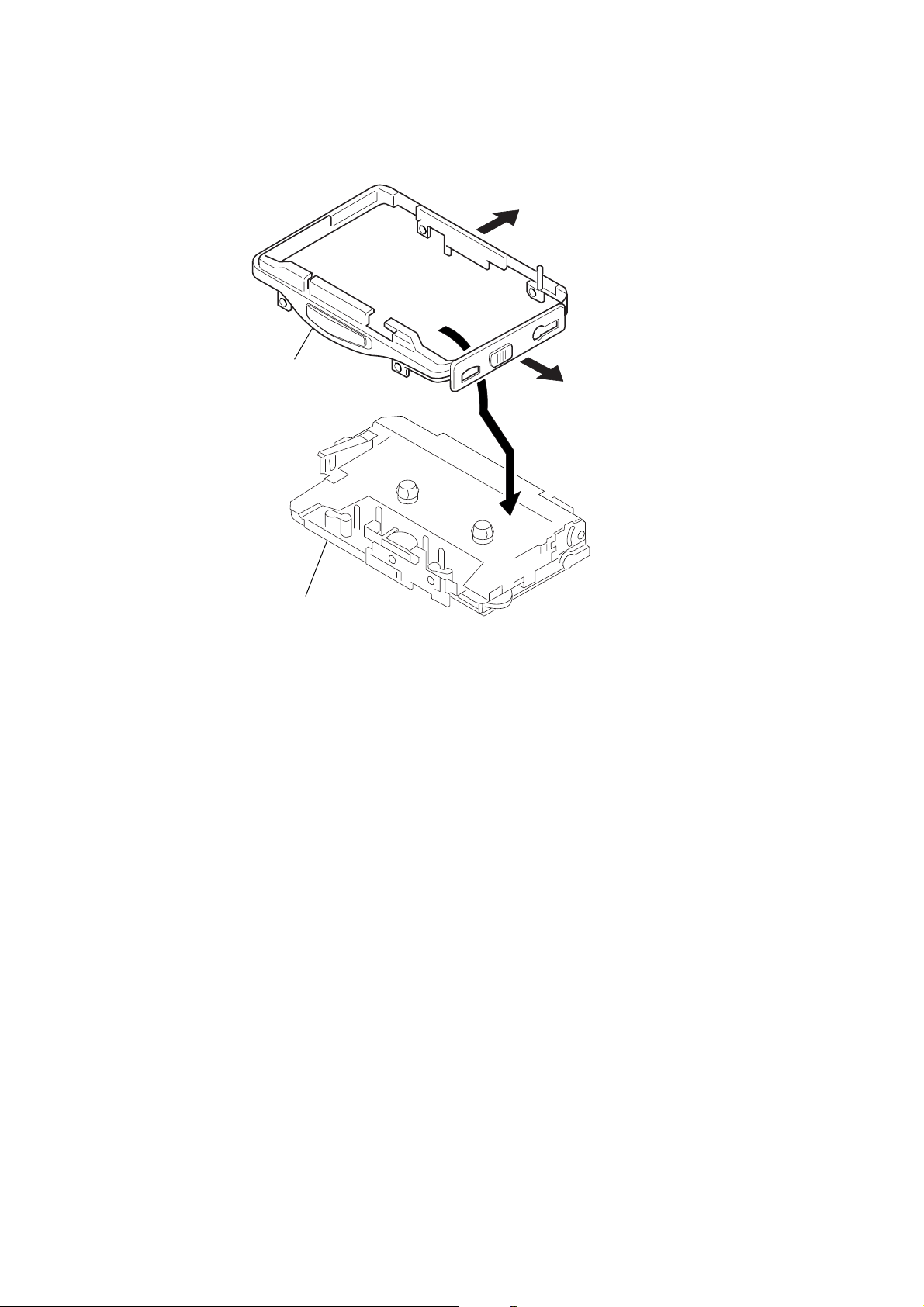
3-2. TUNER BOARD REMOVAL
4 TUNER board
1 Scew (M1.7 × 6)
2 Scew (M1.7 × 3)
3 Scew
(M1.4 × 4.5)
6 GUIDE (TU )
5
— 4 —
3-3. AUDIO BOARD REMOVAL
7 AUDIO board
4 Flexible board
2 Remove solder
1 Screw (M1.7 × 3)
6
3 Remove solder
5
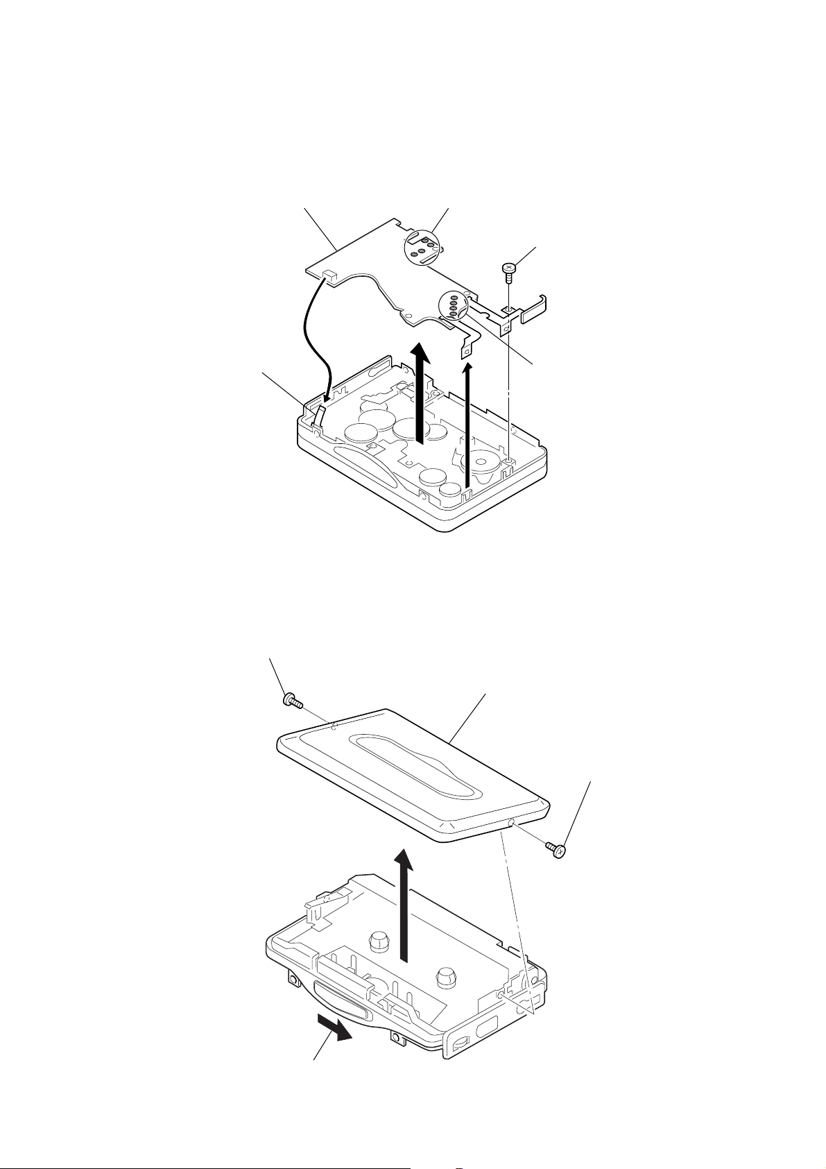
3-4. CASSETTE LID ASSY REMOVAL
2 Screw (M1.4 × 2)
5 Cassette lid assy
3 Screw (M1.4 × 2)
4
1 OPEN button
— 5 —
3-5. MECHANISM DECK REMOVAL
2
4 Reel ornament
5 Mechanism deck
1
3
— 6 —
SECTION 4
r
)
)
r
MECHANICAL ADJUSTMENT
SECTION 5
ELECTRICAL ADJUSTMENT
SECTION 6
EXPLANATION OF IC TERMINALS
PRECAUTION
1. Clean the following parts with a denatured-alcahol-moistened
sweb :
Playback head Pinch roller
Rubber belt Capstan
2. Demagnetize the playback head using a demagnetizer.
3. Do not use a magnetized screwdriver for adjustments.
4. After adjusting, apply screw-locking compound onto the
adjusted parts.
5. Unless specified otherwise, use a specified voltage (1.3V) to
perform the adjustments.
Torqu Measurement
Mode
FWD
FWD
Back Tension
REV
REV
Back Tension
FF
REW
Torqu meter
CQ-102C
CQ-102RC
CQ-201B
Meter reading
20 - 30 g · cm
0.4 - 2.0 g · cm
20 - 30 g · cm
0.4 - 2.0 g · cm
More than 40 g · cm
PRECAUTION
1. Specified voltage : 1.3V
2. Switch position
DOLBY NR switch : OFF
AVLS switch : OFF
CASSETTE SECTION
Test Tape
Type
WS-48A
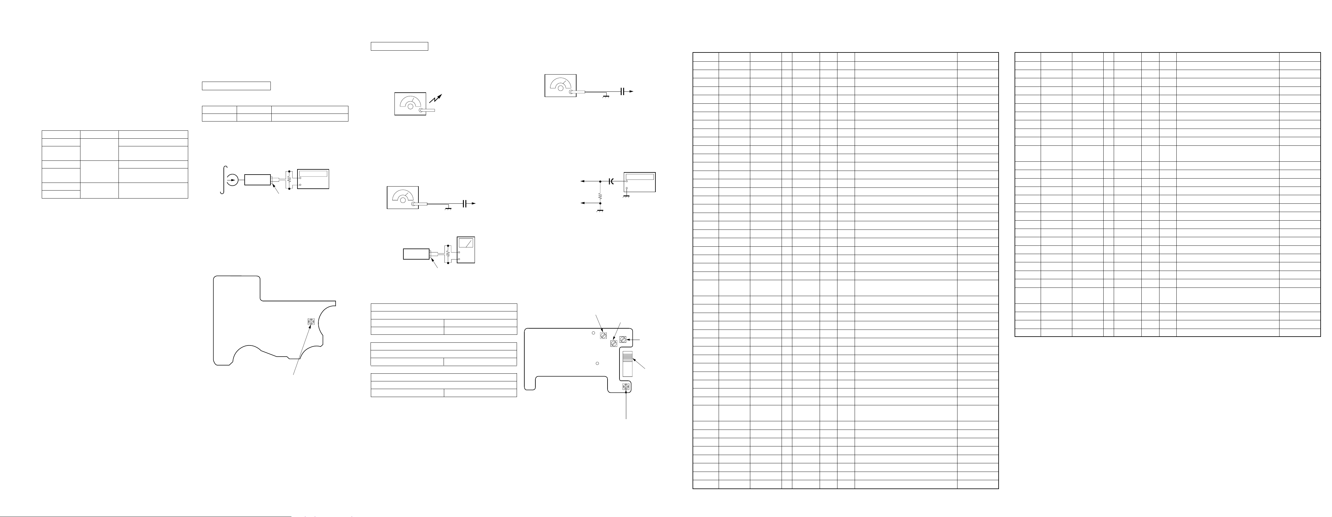
Tape Speed Adjustmnet
Procedure :
Test tape
WS-48A
(3kHz, 0dB)
1. Playback WS-48A (Tape center part) in the FWD state and
adjust RV601 so that the frequency counter reading becomes
3,000Hz ± 30Hz.
2. Playback WS-48A (Tape center) in the REV state.
Check that frequency counter reading is within 2.0% of the
reading of step1.
Adjustment Point :
[MAIN BOARD] — SIDE A —
Signal
3kHz, 0dB
Set
Purpose
Tape Speed Adjustment
Frequency counte
16Ω
+
–
PHONES jack
RV601 : Tape speed
TUNER SECTION
[AM]
BAND switch : AM
AM RF signal
generator
30% amplitude modulation
by 400Hz signal.
Output level : as low as possible
[FM]
BAND switch : FM
FM RF signal
generator
22.5kHz frequency
deviation by 400Hz signal.
Output level : as low as possible.
Set
• Repeat the procedures in each adjustment several times, and the
frequency coverage and tracking adjustments should be finally
done by the trimmer capacitors.
AM TRACKING ADJUSTMENT
Adjust for a maximum reading on level meter.
L4 621kHz
CT1 1,395kHz
FM IF ADJUSTMENT
Adjust for a maximum reading on level meter.
L3 10.7MHz
FM VT VOLTAGE ADJUSTMENT
L2 76MHz
Put the lead-wire antenna
close to the set.
0.01µF
to ANT (TP1
Level meter
32Ω
+
–
PHONES
1.1V ± 0.05V
FM VCO Adjustment
Procedure :
FM RF signal
generator
0.01µF
to ANT (TP1
Carrier frequency : 98MHz
Modulation : No moduration
Output level : 0.1V (100dB)
1. Connect the frequency counter to the positions shown below.
2. Turn the set to 98MHz.
3. Adjust RV1 for 19kHz ± 100Hz reading on the frequency
counter.
Frequency counte
TP23
(IC7 pin !“)
IC7 pin 9
1µF
+
–
100Ω
Adjustment Parts Location :
[TUNER BOARD] — SIDE A —
L2 : FM VT
Voltage Adjustment
L3 : FM IF Adjustment
TP1
TP13
RV1 : FM VCO Adjustment
CT1 : AM Tracking
Adjustment
L4 : AM Tracking
Adjustment
• IC1 TC9326F
Pin No.
1
2
3
4
5
6
7
8
9
10
11
12
13
14
15
16
17
18
19
20
21
22
23
24
25
26
27
28
29
30
31
32
33
34
35
36
37
38
39
40
41
42
43
44
45
46
47
48
49
Function
COM 1
COM 2
COM 3
R DATA OUT
DDC1 CTL
BAND AM/FM
MUTE CTL
F/R CTL
BST CTL
IF REQ
HOLD SW
R DATA IN
HOLDER, TUME
F/R SW
HOLD SENS
PHOTO CTL
PHOTO IN
AMS CTL
AMS IN
BATT DET
KEY IN
AD Vref
LED CTL
M DATA I/O
M CLOCK
S1
S2
S3
S4
S5
S6
S7
S8
S9
S10
S11
S12
S13
S14
S15
S16
S17
S18
S19
S20
S21
S22
CS
BEEP
Pin Name
COM 1
COM 2
COM 3
S1
S2
S3
S4
S5
S6
S7
S8
S9
S10
S11
S12
S13
S14
S15
S16
S17
S18
S19
S20
S21
S22
P13-1
P13-2
P13-3
P14-0
P14-1
P14-2
P14-3
IN2
K0
K1
K2
K3
P1-1
P1-2
P1-3
P2-0/AD IN1
P2-1/AD IN2
P2-2
P2-3
P3-0
P3-1
P3-2
P3-3/BUZR
P4-0
I/O
O
O
Output (Nch)
O
Output (Nch)
O
Output (Nch)
O
Output (Nch)
O
Output (Nch)
O
Output (Nch)
I
I
I
I
I
O
Input/Output
I
Input/Output
O
Input/Output
I
Input/Output
I
Input/Output
I
Input/Output
I
Input/Output
O
Input/Output
O
Input/Output
I/O
Input/Output
O
Input/Output
O
Input/Output
Circuit
Output
Input
Input
Input
Input
Input
INT
—
—
—
—
—
—
—
—
—
—
—
—
—
—
—
—
—
—
—
—
—
—
—
—
—
H
Hi-imp
Hi-imp
Hi-imp
Hi-imp
L
Hi-imp
—
L
—
—
L
L
—
L
—
—
H
—
L
L
L
L
—
ACT
Common terminal.
—
Common terminal.
—
Common terminal.
—
Segment output terminal.
—
Segment output terminal.
—
Segment output terminal.
—
Segment output terminal.
—
Segment output terminal.
—
Segment output terminal.
—
Segment output terminal.
—
Segment output terminal.
—
Segment output terminal.
—
Segment output terminal.
—
Segment output terminal.
—
Segment output terminal.
—
Segment output terminal.
—
Segment output terminal.
—
Segment output terminal.
—
Segment output terminal.
—
Segment output terminal.
—
Segment output terminal.
—
Segment output terminal.
—
Segment output terminal.
—
Segment output terminal.
—
Segment output terminal.
—
Remote control data output.
—
DDC control terminal (when DDC ON = L).
L
BAND control output (when AM = Hi-imp, when FM = L).
—
MUTE control terminal (when MUTE ON = L).
L
HEAD select terminal (when FWD = Hi-imp, when REV = L).
—
Tone control terminal (when BOOST ON = Hi-imp, when OFF = L).
Hi-imp
IF REQ control terminal (when REQ = Hi-imp).
L
HOLDER detect input (when HOLDER CLOSE = H).
—
Communication request from the remote controller. (H = VCC).
VCC
HOLDER detect and TAPE error erase detect terminal.
—
TAPE rotating direction detect terminal.
—
Input when the key is pressed during HOLD (H = AD Vref).
AD Vrcl
Terminal for controlling the rotation detect circuit.
H
Rotation detect input.
—
AMS sensitivity select (when AMS = H, when BL.SKIP = L).
H
Tape sound existing or not-exiting detect (Music
—
exists: L, music does not exist: H.
Voltage detect input.
—
KEY input terminal.
—
Reference voltage of AD IN 1, 2.
—
LED output terminal.
H
E2PROM CS control terminal.
—
E2PROM DATA I/O.
—
E2PROM CLOCK terminal.
—
BEEP (when TC : 1.6 kHz, when CF : 3.0 kHz).
—
Description
Remarks
VLD at High level.
Pull-up at outside
(TUNER side).
Pull-up at outside (Vref).
Pull-up at outside (Vcc).
Pull-up at outside (Vcc).
Pull-up at outside (Vcc).
Pull-up at outside (Vref).
Pull-up at outside (V
A/D input.
A/D input.
A/D input.
A/D input.
Pull-down at outside.
Pull-up at outside.
LCD
).
Pin No.
50
51
52
53
54
55
56
57
58
59
60
61
62
63
64
65
66
67
68
69
70
71
72
73
74
75
76
77
78
79
80
Function
MOTOR CTL
MOTOR DIR
MOTOR BRK
REC CTL
RADIO CTL
AVLS CTL
AMP CTL
GRV/MB CTL
PM CTL
PRE AMP CTL
DOLBY CTL
DDC2 CTL
MONO/ST
TEST
IF IN
LOCAL/DX
DO
HOLD
PSC
GND
FM IN
AM IN
VDD
RESET
XOUT
XIN
VXT
VLCD
C1
C2
VEE
Pin Name
P4-1
P4-1
P4-2
P4-3
P5-0
P5-1
P5-2
P5-3
P6-0
P6-1
P6-2
P6-3
MUTE
TEST
IF IN
DO1/OT
DO2
HOLD
PSC
GND
FM IN
AM IN
VDD
RESET
XOUT
XIN
VXT
VLCD
C1
C2
VEE
I/O
Circuit
O
Input/Output
O
Input/Output
O
Input/Output
O
Input/Output
O
Input/Output
O
Input/Output
O
Input/Output
O
Input/Output
O
Ternary output
O
Ternary output
O
Ternary output
O
Ternary output
O
Output
O
Output
I
External interrupt
INT
L
L
L
L
H
L
L
L
L
Hi-imp
Hi-imp
Hi-imp
L
—
—
L
—
H
—
—
—
—
—
L
—
—
—
—
—
—
—
ACT
H
MOTOR control terminal.
H
MOTOR control terminal.
H
REC circuit control output.
H
RADIO system control terminal (when RADIO ON = L).
L
Terminal for controlling AVLS (when ON = L).
L
AMP control output (when AMP ON = H).
H
Tone control terminal (when GRV = L, when MB = H).
H
PL control terminal.
H
TC/CF select output (when PRE OFF = H, when PRE ON = Hi-imp).
Hi-imp
Terminal for controlling DOLBY circuit
Hi-imp
(when OFF = H, when ON = Hi-imp).
DDC control terminal (ON at Hi-imp, OFF at L).
Hi-imp
TUNER MONO/STEREO select terminal (MONO at H).
—
TEST terminal (Normal operation at L or NC).
—
IF input.
—
TUNER sensitivity select terminal (LOCAL at H, DX at L).
—
Phase comparator output.
—
External interrupt terminal.
—
Pre-scaler output (FM at H).
H
Power supply GND terminal.
—
Pre-scaler input.
—
AM local oscillator output.
—
Power supply voltage.
—
RESET terminal (H during operation).
H
Terminal to which external oscillator is connected.
—
Terminal to which external oscillator is connected.
—
Terminal to which external capacitor is connected
—
to stabilize crystal oscillator power supply.
Terminal to step-up power supply voltage for LCD drive.
—
Terminal to step-up power supply voltage for LCD drive.
—
Terminal to step-up power supply voltage for LCD drive.
—
Terminal for 1.5 V constant voltage power supply of LCD drive.
—
Description
MOTOR control terminal.
Remarks
Open
— 7 — — 8 — — 9 — — 10 —
 Loading...