

Sony WMFX-521 Service manual
WM-FX521
SERVICE MANUAL
Ver 1.0 2002.01
SPECIFICATIONS
Radio section
Frequency range
FM: 87.5 - 108 MHz
AM: 530 - 1 710 kHz (North, Central, and South America)
531 - 1 602 kHz (other countries)
Tape section
Frequency response
Playback: 40 - 15 000 Hz
Output
Headphones (i) jack
Load impedance 8 - 300 Ω
General
Power requirements
1.5 V
One R6 (size AA) battery
Dimensions (w/h/d)
Approx. 77.0 × 108.4 × 28.7 mm, excl. projecting parts and
controls
Mass
Approx. 165 g (main unit only)
US Model
AEP Model
E Model
Chinese Model
Model Name Using Similar Mechanism NEW
Tape Transport Mechanism T ype MT-WMEX505-162
Supplied accessories
• Stereo headphones/earphones with remote control or stereo
headphones/earphones (1)
Design and specifications are subject to change without notice.
Battery life (Approx. hours) (JEITA*)
Sony alkaline LR6 (SG)** 35 65
* Measured value by the standard of JEITA (Japan Electronics
and Information Technology Industries Association). (Using
a Sony HF series cassette tape)
**When using a Sony LR6 (SG) “STAMINA” alkaline dry
battery (produced in Japan).
Note
•
The battery life may be shorter depending on the
operating condition, the surrounding temperature
and battery type.
Tape playback Radio reception
9-873-469-01 Sony Corporation
2002A0500-1 Personal Audio Company
C 2002.1 Published by Sony Engineering Corporation
RADIO CASSETTE PLAYER

WM-FX521
TABLE OF CONTENTS
1. SERVICING NOTES ............................................... 3
2. GENERAL ................................................................... 5
3. DISASSEMBLY
3-1. Disassembly Flow ........................................................... 6
3-2. Lid Cassette Assy ............................................................ 6
3-3. Case Block Assy.............................................................. 7
3-4. Ornament Reel ................................................................ 7
3-5. Battery Holder................................................................. 8
3-6. Belt (F2) .......................................................................... 8
3-7. MAIN Board ................................................................... 9
3-8. Motor (Capstan/Reel) (M901) ........................................ 10
3-9. Holder (FS) Assy ............................................................. 10
3-10. Pinch Lever (N) Assy, Pinch Lever (R) Assy ................. 11
3-11. Magnetic Head (Playback) (HP901) .............................. 11
4. MECHANICAL ADJUSTMENTS....................... 12
5. ELECTRICAL ADJUSTMENTS......................... 12
6. DIAGRAMS
6-1. Block Diagram – TUNER Section – ............................. 15
6-2. Block Diagram – MAIN Section –................................ 16
6-3. Note for Printed Wiring Board
and Schematic Diagrams ................................................ 17
6-4. Schematic Diagram – MAIN Board (1/2) – .................. 18
6-5. Schematic Diagram – MAIN Board (2/2) – .................. 19
6-6. Printed Wiring Board ...................................................... 20
6-7. IC Pin Function Description ........................................... 23
Notes on chip component replacement
• Never reuse a disconnected chip component.
• Notice that the minus side of a tantalum capacitor may be damaged by heat.
Flexible Circuit Board Repairing
• Keep the temperature of the soldering iron around 270 ˚C during repairing.
• Do not touch the soldering iron on the same conductor of the
circuit board (within 3 times).
• Be careful not to apply force on the conductor when soldering
or unsoldering.
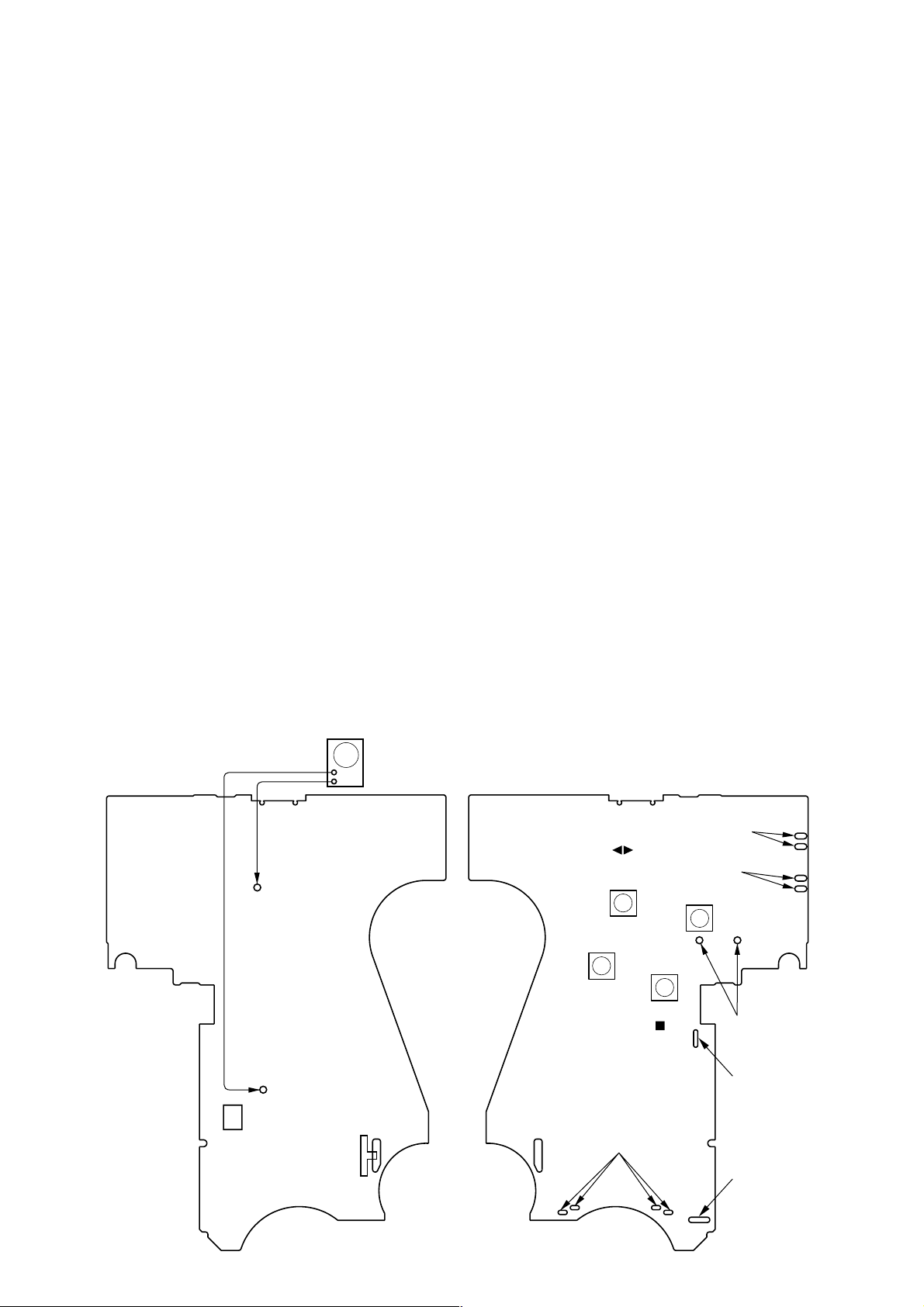
7. EXPLODED VIEWS
7-1. Case Section .................................................................... 25
7-2. Bracket, MAIN Board Section ....................................... 26
7-3. Mechanism Deck Section (MT-WMEX505-162) .......... 27
8. ELECTRICAL PARTS LIST ............................... 28
SAFETY-RELATED COMPONENT WARNING!!
COMPONENTS IDENTIFIED BY MARK 0 OR DOTTED
LINE WITH MARK 0 ON THE SCHEMATIC DIA GRAMS
AND IN THE PARTS LIST ARE CRITICAL TO SAFE
OPERATION. REPLACE THESE COMPONENTS WITH
SONY PARTS WHOSE PART NUMBERS APPEAR AS
SHOWN IN THIS MANUAL OR IN SUPPLEMENTS PUBLISHED BY SONY.
2
SECTION 1
SERVICING NOTES
WM-FX521
This set detects the rotation of the idler gear (A) (side S) using the
PH701 (photo reflector). The PH701 is mounted on the MAIN
board, therefore the idler gear (A) (side S) cannot be detected with
the MAIN board removed. As a result, the motor (M901) cannot
be controlled, causing malfunction.
Further, the DIRECTION switch (S703) is also mounted on the
MAIN board, and with the board removed, the mechanism position cannot be detected and the operation is not changed over.
Therefor, when the voltage check is e xecuted with the MAIN board
removed, follow the procedure provided below.
1. Setting
(1) Refer to “3. DISASSEMBL Y”, and remov e the MAIN board.
(2) Connect the MAIN board to the motor (M901) and the
plunger (PM901) using jumper wires. These can be connected
easily with the use of the extension tool (Part No. 1-769143-11) (ten in one set).
(3) Short the TAPE DETECT switch (S901-1) terminals and the
ATS switch (S901-2) terminals.
(4) Connect the AF oscillator to the TP40 (PHOTO IN) and the
TP2 (GND).
(5) Supply 1.3 V to the battery terminals using the regulated
power supply.
2. Preset state
T o set the PLAY , FF, REW modes, the preset state must be set.
(1) Check that the slider (NRA) and the DIRECTION switch
(S1) are set to the center position. If not, set the preset state
as follow.
(2) Move the DIRECTION switch (S703) to the side, which the
slider (NRA) is facing.
(3) The slider (NRA) will move when the regulated power sup-
ply switch is set to OFF once and then set to ON. Move the
DIRECTION switch (S703) according to this timing and set
to the center position.
3. FF, REW modes
(1) Check that the preset state is set.
(2) Input the square wave or sine wa ve to the TP40 (PHOT O IN)
and the TP2 (GND).
(3) Press the [RADIO OFF ] button (S709) to set the STOP
x
mode.
(4) Press the [FF AMS] button (S707) or the [REW AMS] but-
ton (S708).
4. PLAY mode
(1) Check that the preset state is set.
(2) Input the square wave or sine wa ve to the TP40 (PHOT O IN)
and the TP2 (GND).
(3) Press the [RADIO OFF ] button (S709) to set the STOP
x
mode.
(4) Press the [ REPEAT] button (S710) will mo v e the slider
Y
(NRA) once towards the side R and then to the side F. Move
the DIRECTION switch (S703) according to this timing will
set the PLA Y mode (side F). Press the [ REPEAT] button
Y
(S710) another time and move the DIRECTION switch
(S703) according to the movement of the slider (NRA) will
set the PLAY (R mode).
Note 1: If the above fails, perform from preset again.
Note 2: Use the [ REPEAT] (S710), [RADIO OFF ] (S709), [FF AMS]
Note 3: When using headphones, the timing for move the DIRECTION
Y
(S707), and [REW AMS] (S708) buttons on the remote controller as much as possible. If no remote controller, do not touch the
buttons with your hands, but using a stick with a round tip.
switch (S703) can be determined from the beep sound.
x
– MAIN BOARD –
square wave
(sine wave)
10 Hz, – 3.5 dB
TP2
(GND)
TP40
(PHOTO IN)
PH701
AF oscillator
+
–
S703
DIRECTION
FWD
R
STOP
r
REV
REPEAT
(S710)
REW AMS
(S708)
RADIO OFF
connect to the
motor (M901)
TAPE DETECT
(S709)
(S901-1)
ATS
(S901-2)
FF AMS
(S707)
connect to the plunger
(PM901)
battery
terminal
battery
terminal
3
#
3
WM-FX521
g
y
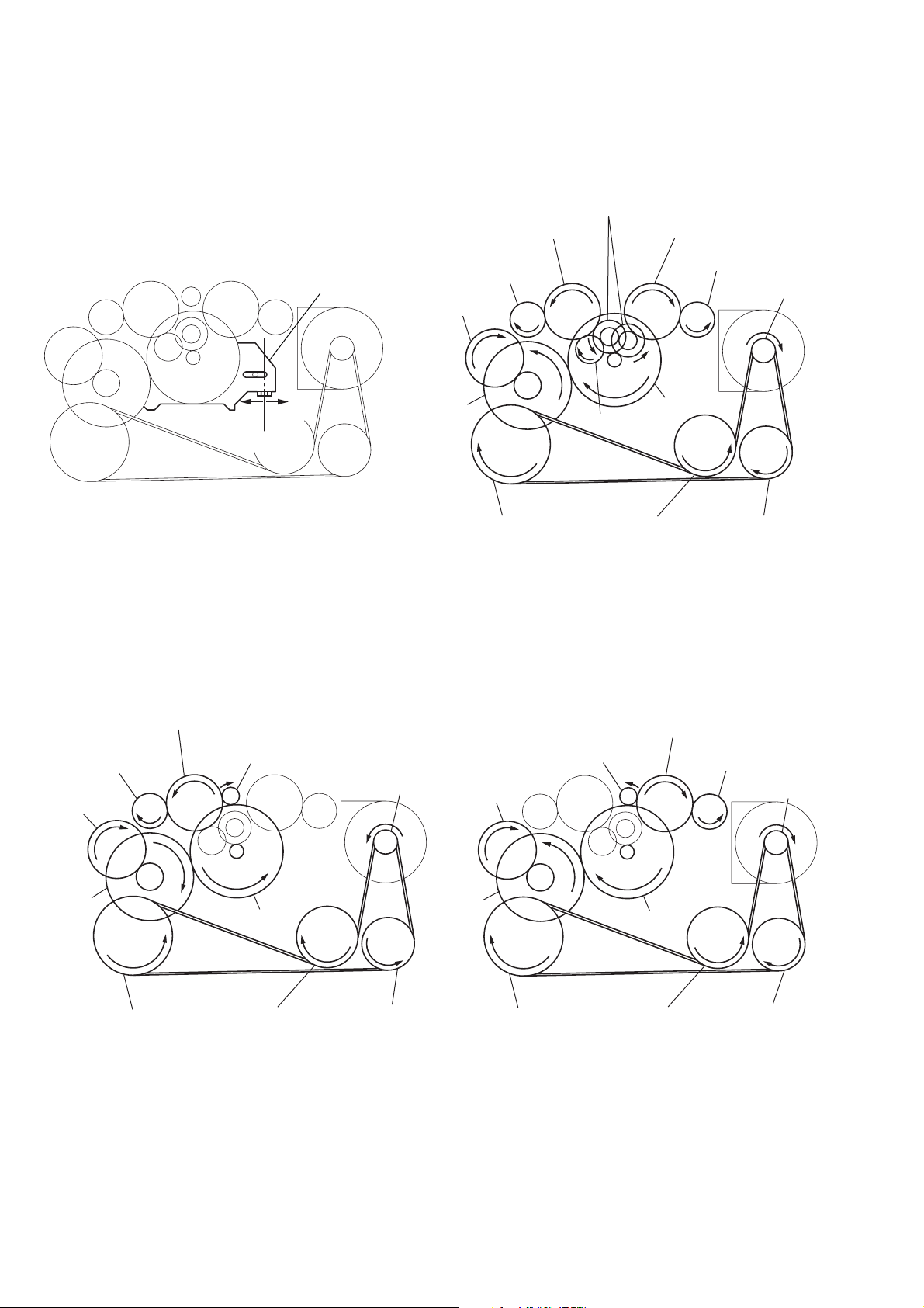
SLIDER (NRA) Rotation system
Rotation system during PLAY
idler (A) gear (T side)
gear (NR)
(FWD: left side
REW: right side)
idler (A) gear (S side)
gear (REEL) (T side)
cam gear
gear (Y)
insert flywheel (N)
idler (B) gear
insert flywheel (R)
side F
slider (NRA)
side R
center
Rotation system during FF Rotation system during REW
gear (REEL) (S side)
motor pulle
clutch assy (F)
reverse pulley
gear (REEL)
(T side)
cam gear
ear (Y)
idler (A) gear (T side)
insert flywheel (N)
gear (FR)
(FF: left side)
clutch assy (F)
insert flywheel (R)
motor pulley
reverse pulley
cam gear
gear (Y)
gear (FR)
(REW: right side)
insert flywheel (N)
idler (A) gear (S side)
gear (REEL) (S side)
clutch assy (F)
insert flywheel (R)
motor pulley
reverse pulley
4
SECTION 2
GENERAL
WM-FX521
This section is extracted from
instruction manual.
A
OPEN
B
C
Y•x**
VOL
HOLD
FF
REW
* There is a tactile dot beside VOL on the main unit to show the direction to turn up the volume.
**The button has a tactile dot.
* Un point tactile à côté de VOL sur l’appareil principal indique le sens de rotation du bouton de
volume.
** Le bouton comporte un point en relief.
* Am Hauptgerät befindet sich ein fühlbarer Punkt neben VOL. Dieser gibt die Richtung an, in der
man die Lautstärke erhöht.
** An dieser Taste befindet sich ein fühlbarer Punkt.
FWD (forward) side
Face FWD (avant)
Vorderseite (FWD)
REV (reverse) side
Face REV (inverse)
Rückseite (REV)
Model supplied with headphones/earphones only
Modèle fourni uniquement avec un casque/des écouteurs
Modelle mit Kopfhörer/Ohrhörer
Model supplied with remote control
Modèle fourni avec télécommande
Modelle mit Fernbedienung
HOLD
VOL*
D
Plug in firmly.
Branchez fermement.
Fest einstecken.
i
Y•REPEAT**
FF (AMS)
x
REW (AMS)
SET
MENU
E
RADIO ON/
BAND•OFF
PRESET +
PRESET –
Model supplied with remote control
Modèle fourni avec télécommande
Modelle mit Fernbedienung
F
HOLD
Model supplied with remote control
Modèle fourni avec télécommande
Modelle mit Fernbedienung
TUNE/PRESET –
TUNE/PRESET +
RADIO OFF
BAND•
RADIO ON
ENTER
SET
MENU
Model supplied with headphones/earphones
only
Modèle fourni uniquement avec un casque/
des écouteurs
Modelle mit Kopfhörer/Ohrhörer
HOLD
SET
MENU
Model supplied with headphones/
earphones only
Modèle fourni uniquement avec un casque/
des écouteurs
Modelle mit Kopfhörer/Ohrhörer
TUNE/PRESET –
TUNE/PRESET +
RADIO OFF
BAND•
RADIO ON
ENTER
SET
MENU
HOLD
SET
MENU
RADIO ON/
BAND•OFF
PRESET +
PRESET –
Model supplied with remote control
Modèle fourni avec télécommande
Modelle mit Fernbedienung
TUNE/PRESET –
TUNE/PRESET +
RADIO OFF
BAND•
RADIO ON
ENTER
SET
MENU
Model supplied with headphones/earphones
only
Modèle fourni uniquement avec un casque/des
écouteurs
Modelle mit Kopfhörer/Ohrhörer
TUNE/PRESET –
TUNE/PRESET +
RADIO OFF
BAND•
RADIO ON
ENTER
SET
MENU
5
WM-FX521
• This set can be disassembled in the order shown below.
3-1. DISASSEMBLY FLOW
Note 1: The process described in can be performed in any order.
Note 2: Without completing the process described in , the next process can not be performed.
SET
SECTION 3
DISASSEMBLY
3-2. LID CASSETTE ASSY
(Page 6)
3-4. ORNAMENT REEL
(Page 7)
3-9. HOLDER (FS) ASSY
(Page 10)
3-10. PINCH LEVER (N) ASSY,
PINCH LEVER (R) ASSY
(Page 11)
3-11. MAGNETIC HEAD (PLAYBACK) (HP901)
(Page 11)
3-3. CASE BLOCK ASSY
(Page 7)
3-5. BATTERY HOLDER
(Page 8)
3-7. MAIN BOARD
(Page 9)
3-8. MOTOR (CAPSTAN/REEL) (M901)
(Page 10)
3-6. BELT (F2)
(Page 8)
Note: Follow the disassembly procedure in the numerical order given.
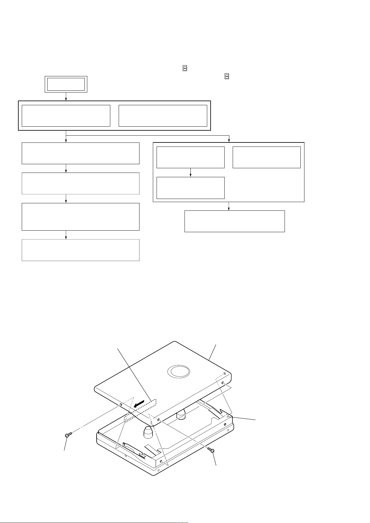
3-2. LID CASSETTE ASSY
1
Open the lid cassette assy.
2
screw
(M1.4)
4
lid cassette assy
2
two screws
(M1.4)
3
boss
6
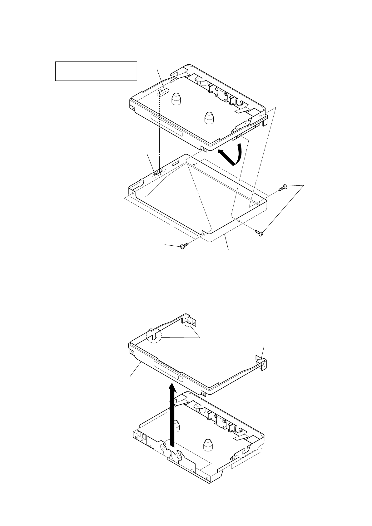
3-3. CASE BLOCK ASSY
WM-FX521
On installation case block assy,
adjust the S701 and knob (hold).
knob (hold)
1
two screws
(M1.4)
S701
2
Remove the case block assy
to direction of the arrow.
1
three screws
(M1.4)
3-4. ORNAMENT REEL
2
ornament reel
1
two claws
1
claw
7
WM-FX521
)
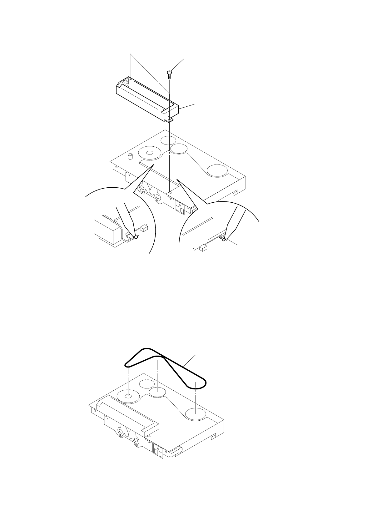
3-5. BATTERY HOLDER
2
two screws
3
battery holder
3-6. BELT (F2)
1
Break the soldering
of battery terminal (–).
1
Break the soldering
of battery terminal (+).
1
belt (F2) (See page 4
8
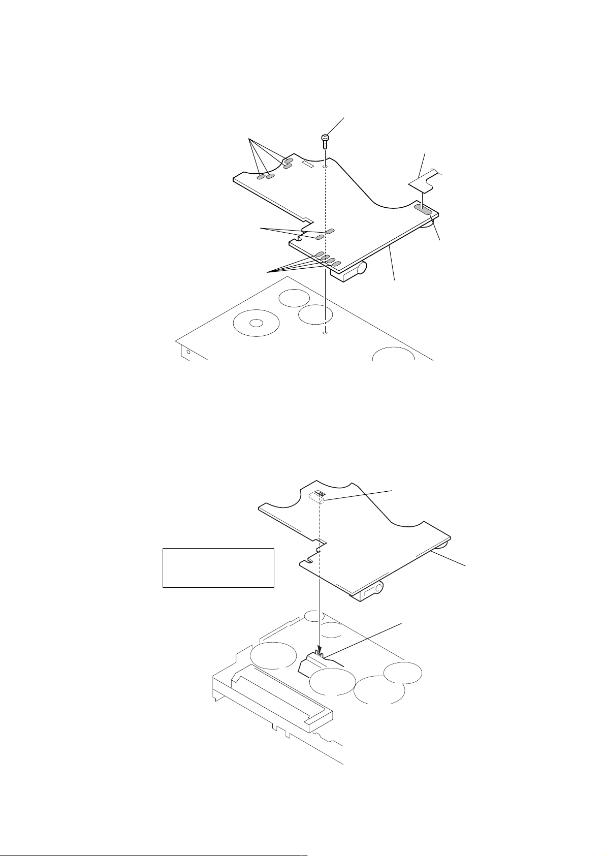
3-7. MAIN BOARD
d
1
Remove four solders
of motor.
1
Remove two solders
of plunger solenoid.
1
Remove four solders
of leaf switch.
2
screw
(M1.4)
flexible board
3
main board
1
Remove six solders
of flexible board.
WM-FX521
NOTE FOR INSTALLATION
• MAIN BOARD
On installation main board,
adjust the S703 and
slider (NRA).
S703
main boar
slider (NRA)
9
WM-FX521
)
)
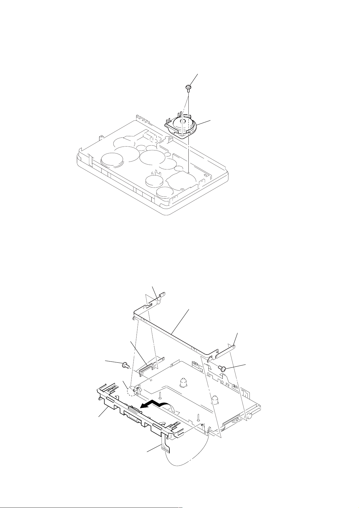
3-8. MOTOR (CAPSTAN/REEL) (M901)
1
two screws
(M1.4)
2
motor (capstan/reel
(M901)
3-9. HOLDER (FS) ASSY
1
two screws
(IB lock)
9
Remove the holder (FS) assy
to direction of the arrow.
3
lock lever (B)
(/M)
6
boss
2
boss
7
bracket (cassette) assy
5
lock lever (S) (/M)
4
screw (M1.4
10
8
Remove six solders
of flexible board.
 Loading...