

Sony WMFX-495 Service manual
WM-FX495
SERVICE MANUAL
Ver. 1.2 2005.12
Model Name Using Similar Mechanism NEW
MD Mechanism Type MF-WMFX495-147
SPECIFICATIONS
US Model
AEP Model
• Frequency range
FM : 87.5 - 108 MHz
AM: 530 - 1 710 kHz (North, America)
531 - 1 602 kHz (Other countries)
• Output
Headphones (i) jack Load impedance 8 - 300 Ω
• Power requirements
1.5V DC, battery R6 (size AA) x 1
• Dimensions (w/h/d)
Approx. 81.1 x 111.2 x 29.3 mm (31⁄4 x 41⁄2 x13⁄16 in.), excl.
projecting parts and controls
• Mass
Approx. 137 g (4.9 oz) (main unit only)
• Supplied accessories
Stereo headphones or earphones with remote control (1)
Carrying case or Carrying pouch or Hand strap (1)
Design and specifications are subject to change without notice.
Battery life* (approximate hours)
Sony alkaline Sony R6P
LR6 (SG)** (SR)
Tape playback 35 9
Radio reception 40 14
* Measured value by the standard of JEITA (Japan Electronics and
Information Technology Industries Association).
(Using a Sony HF series cassette tape)
**When using a Sony LR6(SG) “STAMINA” alkaline dry
battery (produced in Japan).
Note
• The battery life may be shorter depending on the operating condition, the
surrounding temperature and battery type.
9-877-098-03
2005L02-1
© 2005.12
RADIO CASSETTE PLAYER
Sony Corporation
Personal Audio Division
Published by Sony Engineering Corporation

WM-FX495
TABLE OF CONTENTS
Specifications ........................................................................... 1
1. SERVICING NOTE ...................................................... 3
2. GENERAL ...................................................................... 4
3. DISASSEMBLY
3-1. Cabinet (Front)Sub Assy ............................................ 5
3-2. Main Board ................................................................. 6
3-3. Mechanism Deck ........................................................ 6
3-4. Cassette Holder Sub Assy........................................... 7
4. ADJUSTMENTS
4-1. Mechanical Adjustments ............................................ 8
4-2. Electrical Adjustments ................................................ 8
5. DIAGRAMS
5-1. Block Diagram ........................................................... 11
5-2. Printed Wiring Boards .............................................. 12
5-3. Schematic Diagram –Main Section (1/2)– ............... 13
5-4. Schematic Diagram –Main Section (2/2)– ............... 14
5-5. IC Block Diagrams ................................................... 15
6. EXPLODED VIEWS
6-1. Cabinet Section ......................................................... 17
6-2. Mechanism Deck Section
(MF-WMFX495-147) ....................... 18
Flexible Circuit Board Repairing
• Keep the temperature of the soldering iron around 270°C during
repairing.
• Do not touch the soldering iron on the same conductor of the
circuit board (within 3 times).
• Be careful not to apply force on the conductor when soldering or
unsoldering.
Notes on chip component replacement
• Never reuse a disconnected chip component.
• Notice that the minus side of a tantalum capacitor may be damaged by heat.
7. ELECTRICAL PARTS LIST ................................... 19
2
SECTION 1
p
SERVICING NOTES
WM-FX495
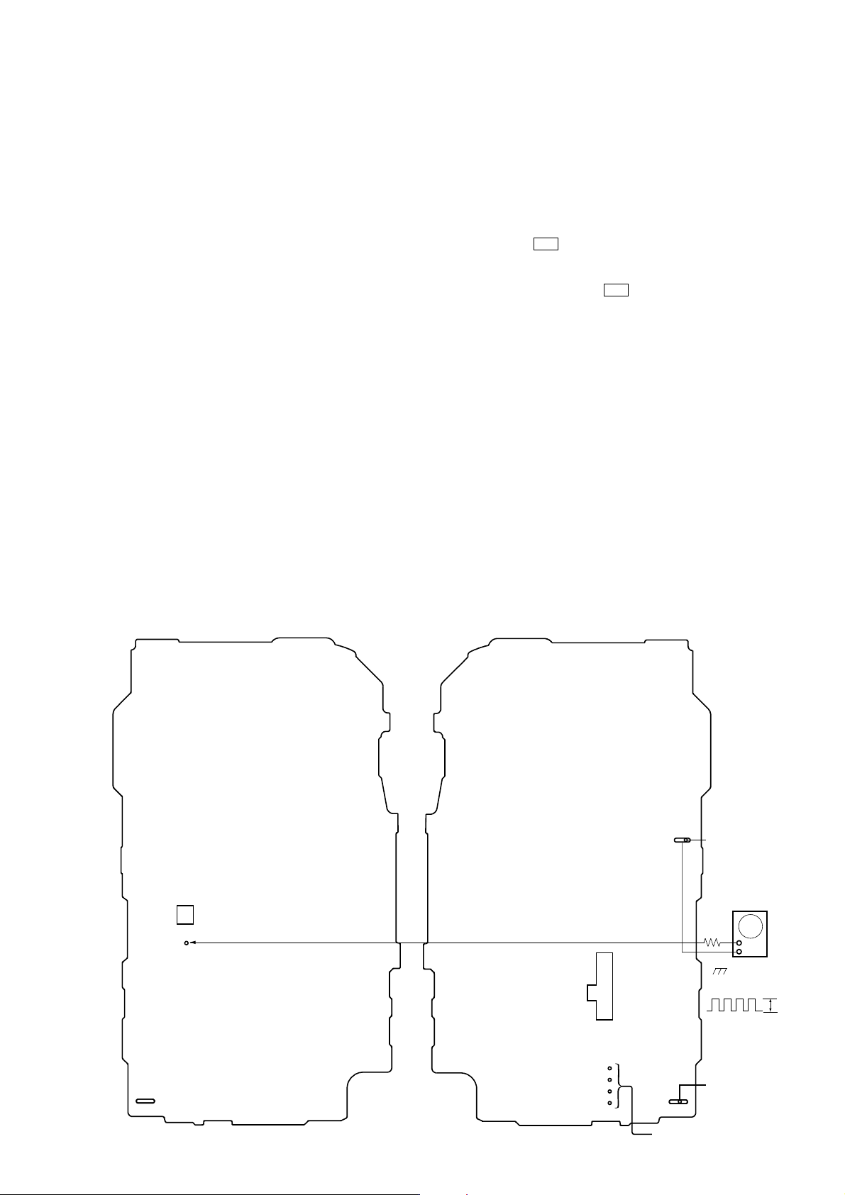
This set detects the rotation of the idler gear (A) (side S) using the
photo reflector (PH751). The PH751 is mounted on the MAIN
board, therefore the idler gear (A) (side S) cannot be detected with
the MAIN board removed. As a result, the motor (M601) cannot
be controlled, causing malfunction.
Further, the MD CONT switch (S601) is also mounted on the
MAIN board, and with the board removed, the mechanism position cannot be detected and the operation is not changed over.
Therefore, when the voltage check is executed with the MAIN
board removed, follow the procedure provided below.
1. Setting
1) Refer to “3. DISASSEMBLY”, and remove the MAIN board.
2) Connect the MAIN board to the motor (M601) using jumper
wires. These can be connected easily with the use of the
extension tool (Part No. 1-769-143-11) (ten in one set).
3) Connect the AF oscillator to the TP752 and the BT401 (BATT–
).
4) Supply 1.5 V to the battery terminals using the regulated power
supply.
2. Preset state
To set the PLAY, FF, REW modes, the preset state must be set.
1) Check that the slider (NRA) and the MD CONT switch (S601)
are set to the center position. If not, set the preset state as follow.
2) Move the MD CONT switch (S601) to the side, which the
slider (NRA) is facing.
3) The slider (NRA) will move when the regulated power supply
switch is set to OFF once and then set to ON. Move the MD
CONT switch (S601) according to this timing and set to the
center position.
3. FF, REW modes
1) Check that the preset state is set.
2) Input the square wave or sine wave to the TP752 and the BT401
(BATT–).
3) Press the [FF] button or [REW] button .
4. PLAY mode
1) Check that the preset state is set.
2) Input the square wave to the TP752 and the BT401 (BATT–).
3) Press the Y button will move the slider (NRA) once towards
the side REV and then to the side FWD. Move the MD CONT
switch (S601) according to this timing will set the PLAY mode
(side FWD). Press the Y button another time for a second
and move the MD CONT switch (S601) according to the movement of the slider (NRA) will set the PLAY mode (side REV).
Note 1: If the above fails, perform from preset again.
Note 2: When using headphones, the timing for move the MD
CONT switch (S601) can be determined from the beep
sound.
– MAIN Board (Component Side) – – MAIN Board (Conductor Side) –
PH751
TP752
(PHOTO)
RVS
tt
REW
t
FF
FWD
S601
(MD CONT)
BT401
battery terminal
AF oscillator
1k
Ω
+
–
square wave
2 Hz, 2 VdB
battery
terminal
3
#
2Vp-
connect to themotor (M601)
3
WM-FX495
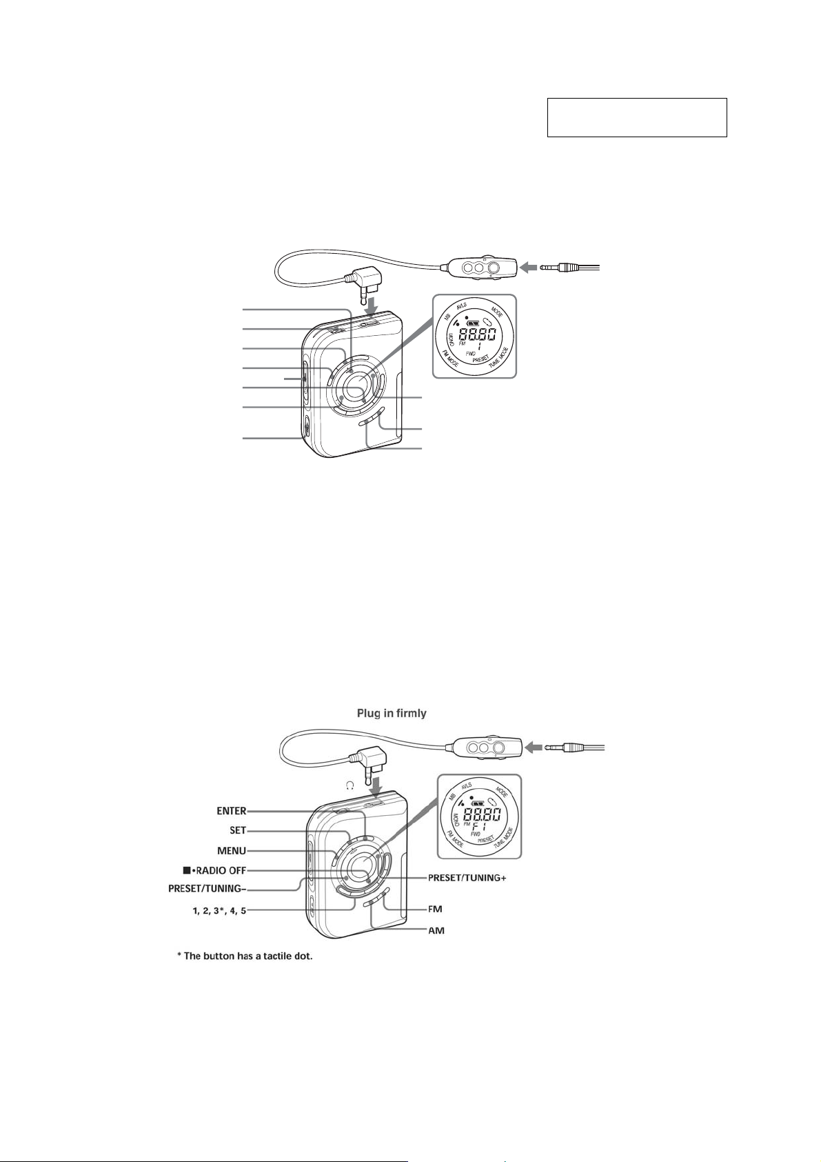
LOCATING THE CONTROLS
–Tape mode–
SECTION 2
GENERAL
This section is extracted from
instruction manual.
Plug in firmly.
–Radio mode–
Y •DIRECTION**
VOL*
SET
MENU
x•RADIO OFF
REW•PRESET/
TUNING –
* There is a tactile dot beside VOL on the main unit to show the direction to turn up the volume.
** The button has a tactile dot.
OPEN
HOLD
i
FF•PRESET/
TUNING+
FM
AM
4
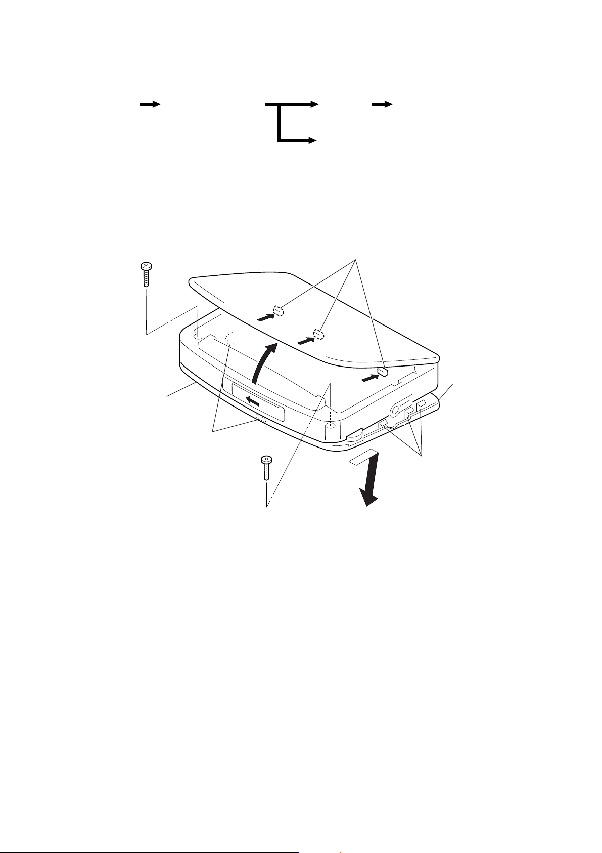
DISASSEMBLY
Y
z
The equipment can be removed using the following procedure.
WM-FX495
SECTION 3
Set
Cabinet (front) sub ASSY
MAIN board
Cassette holder sub ASSY
Note : Follow the disassembly procedure in the numerical order given.
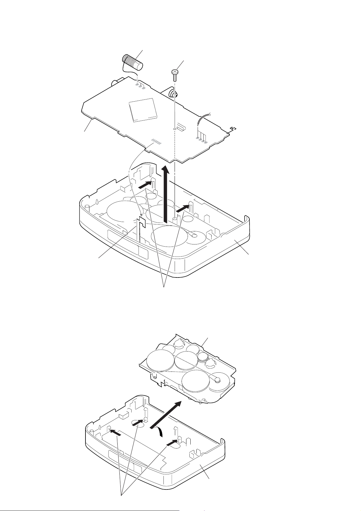
3-1. CABINET (FRONT) SUB ASSY
2
Screw (B 1.7 × 9), tapping
1
Cabinet center
4
Claws
Mechanism deck
8
Cabinet (front) sub ASS
6
Claws
3
Screw (B 1.7 × 9), tapping
7
5
Claws
5
WM-FX495
Y
3-2. MAIN BOARD
7
MAIN board
3
Unsolder L4 leads (three places)
4
Screw (1.7 × 2.5), tapping
6
2
Unsolder leads from motor (four places)
1
Unsolder HEAD flexible board
3-3. MECHANISM DECK
5
Claws
2
3
Mechanism deck
Cabinet (center) ASSY
Cabinet (center) ASS
1
6
Claws
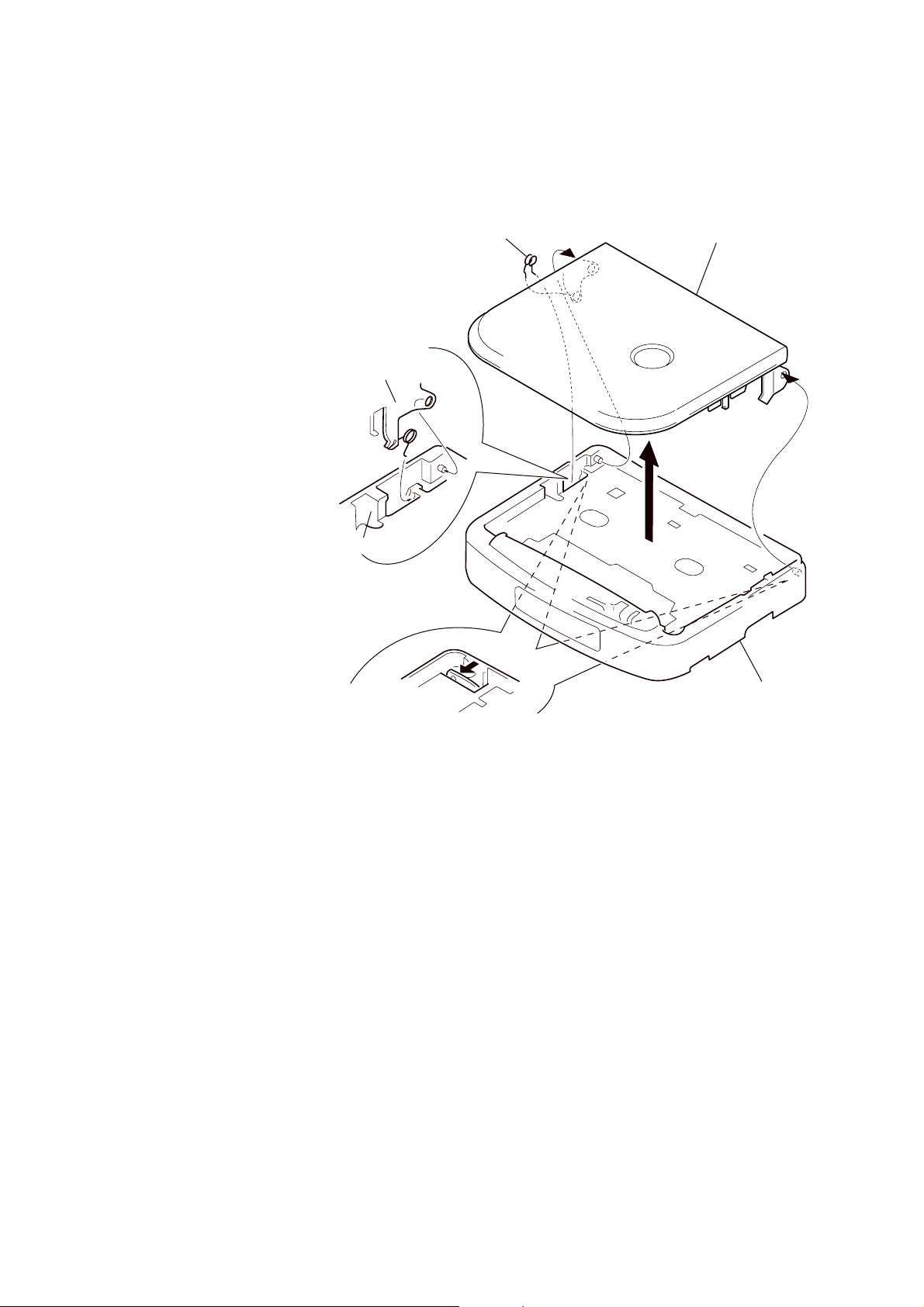
3-4. CASSETTE HOLDER SUB ASSY
Y
• Use caution when installing the cassette holder assy
Install the cassette holder sub ASSY with the spring (lid up)
as shown below in the drawing so that it fits into the holes
on the cabinet center. Once installed, fit the left and right
pieces on.
Cassette holder sub ASSY
3
Spring (lid up)
WM-FX495
4
Cassette holder sub ASS
2
Cabinet center
1
• Press on the left & right clips from the rear of the
cabinet center and remove the boss.
Cabinet center
7
WM-FX495
t
r
SECTION 4
ADJUSTMENTS
4-1. MECHANICAL ADJUSTMENTS
PRECAUTION
1. Clean the following parts with a denatured-alcohol-moistened
swab :
playback head pinch roller
capstan rubber belt
2. Demagnetize the playback head with a head demagnetizer.
Do not use a magnetized screwdriver for the adjustments.
3. These measurement and adjustment should be performed with
the rated power supply voltage (1.5 V) unless otherwise noted.
Torque Measurement
Mode Torque meter Meter reading
FWD
CQ-102C
FWD
back tension
REV 20 – 42 g • cm
CQ-102RC
REV
back tension
FF, REW CQ-201B
1.97 – 4.11 mN • m
20 – 42 g • cm
(0.28 – 0.58 oz• inch)
less than 0.19 mN • m
less than 2 g • cm
(less than 0.027 oz• inch)
1.97 – 4.11 mN • m
(0.28 – 0.58 oz• inch)
less than 0.19 mN • m
less than 2 g • cm
(less than 0.027 oz• inch)
more than 5.89 mN • m
more than 60 g • cm
(more than 0.84 oz• inch)
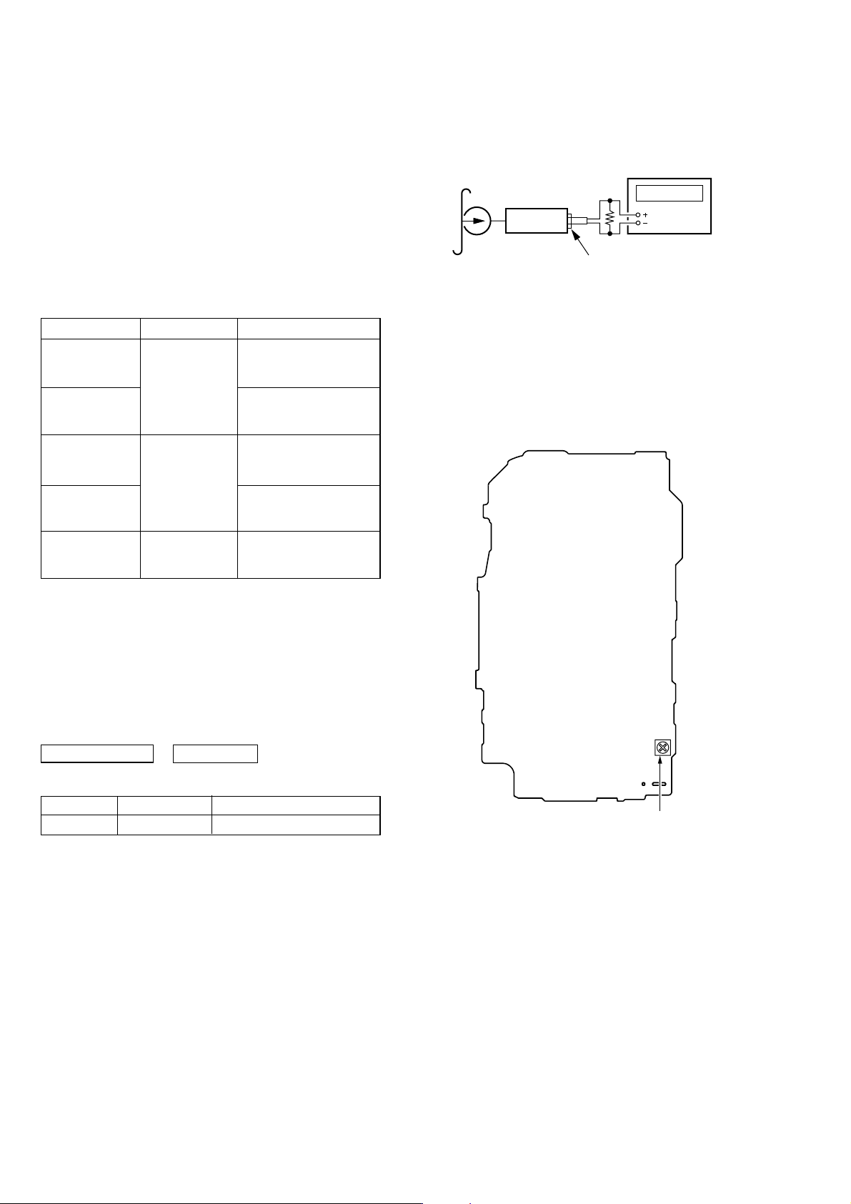
Tape Speed Adjustment
Procedure :
test tape
WS-48A
(3kHz, 0dB)
set
frequency counte
16 Ω
phones jack (J301)
1. Playback WS-48A (tape center part) in the FWD state and adjust RV601 so that the frequency counter reading becomes
3,000Hz.
Standard value : 2,910–3,090Hz
2. Playback WS-48A (tape center part) in the REV state.
Check that frequency counter reading is within ±1.5%
(apporox.45Hz) of the reading of step 1.
Adjustment Location :
MAIN BOARD (SIDE B)
4-2. ELECTRICAL ADJUSTMENTS
PRECAUTION
• Supplied voltage : 1.5V.
• Switch and control position
VOLUME control (RV301) : maximum
HOLD : OFF
TAPE SECTION
Test Tape
Type Signal Used for
WS-48A 3kHz, 0dB Tape Speed Adjustment
0 dB = 0.775V
RV601 : Tape speed adjustmen
8
 Loading...