

Sony WMFX-487, WMFX-483, WMFX-485 Service manual
WM-FX483/FX485/FX487
MICROFILM
SERVICE MANUAL
Ver 1.0 1998.03
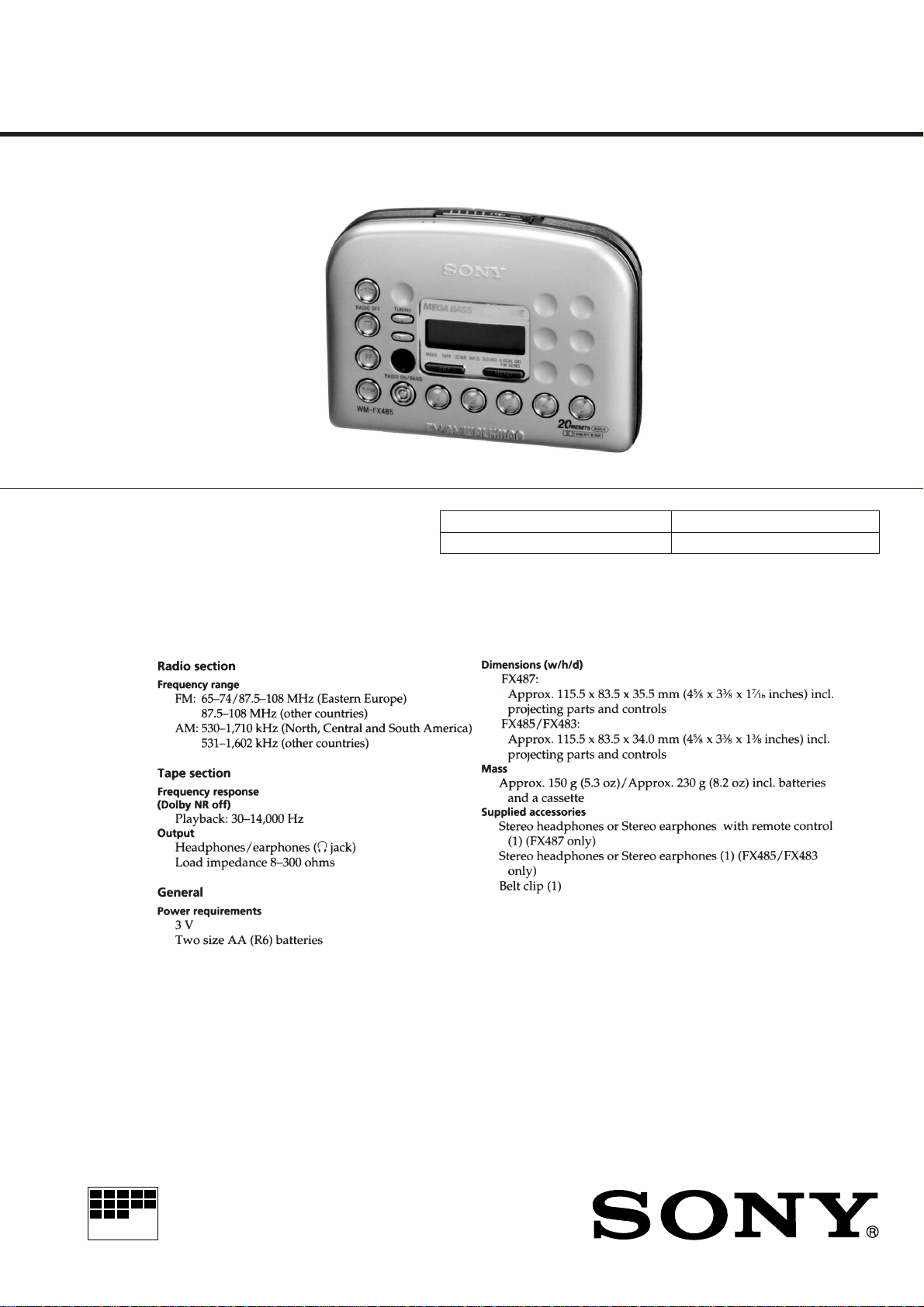
Photo : WM-FX485
Manufactured under license from Dolby
Laboratories Licensing Corporation.
“DOLBY” and the double-D symbol a are
trademarks of Dolby Laboratories Licensing
Corporation.
Model Name Using Similar Mechanism WM-EX402/EX404/EX405/EX406
Tape Transport Mechanism Type MF-WMFX483-147
SPECIFICATIONS
US Model
WM-FX487
Canadian Model
WM-FX485/FX487
AEP Model
E Model
WM-FX483/FX485/FX487
Design and specifications are subject to change without notice.
RADIO CASSETTE PLAYER

TABLE OF CONTENTS
1. GENERAL ······································································ 3
2. DISASSEMBLY
2-1. Cabinet (Front) Assy ·························································· 5
2-2. Main Board········································································· 6
2-3. Mechanism Deck ································································ 6
2-4. Cassette Lid Sub Assy ························································ 7
2-5. Display Board····································································· 7
3. MECHANICAL ADJUSTMENT······························· 8
4. ELECTRICAL ADJUSTMENT ································ 8
5. DIAGRAMS
IC Block Diagrams··························································· 11
5-1. Block Diagram ································································· 13
5-2. Printed Wiring Board -Main Section- ······························ 15
5-3. Schematic Diagram -Main Section- ································· 17
Printed Wiring Board -Display Section-(FX483/FX485
5-4.
5-5. Schematic Diagram
Printed Wiring Board -Display Section-(FX487
5-6.
5-7. Schematic Diagram
5-8. IC Pin Function ································································ 27
-Display Section-(FX483/FX485
-Display Section-(FX487
) ················ 25
)··19
) ···· 21
) ·············· 23
6. EXPLODED VIEWS
6-1. Cassette Lid Section ························································· 29
6-2. Cabinet Section································································· 31
6-3. Mechanism Deck Section················································· 32
Flexible Circuit Board Repairing
• Keep the temperature of the soldering iron aroud 270˚ C during
repairing.
• Do not touch the soldering iron on the same conductor of the
circuit board (within 3 times).
• Be careful not to apply force on the conductor when soldering
or unsoldering.
Notes on chip component replacement
• Never reuse a disconnected chip component.
• Notice that the minus side of a tantalum capacitor may be
damaged by heat.
7. ELECTRICAL PARTS LIST ··································· 33
— 2 —
SECTION 1
GENERAL
— 3 —
— 4 —
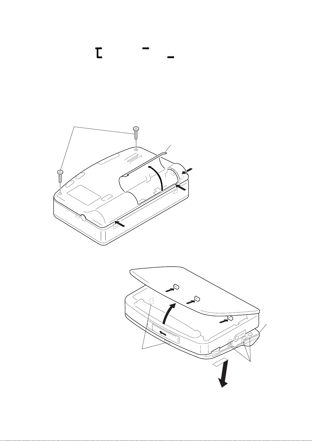
• This set can be disassembled in the order shown below.
SECTION 2
DISASSEMBLY
2-1. CABINET (REAR) ASSY 2-2. MAIN BOARD
2-4. CASSETTE LID SUB ASSY
2-3. MECHANISM DECK
Note : Follow the disassembly procedure in the numerical order given.
2-1. CABINET (REAR) ASSY
1
Screw (B 1.7 × 12), tapping
2
2-5. DISPLAY BOARD
Open the lid battery case.
3
3
3
Claws
5
4
5
5
Cabinet (rear) assy
Claws
6
— 5 —
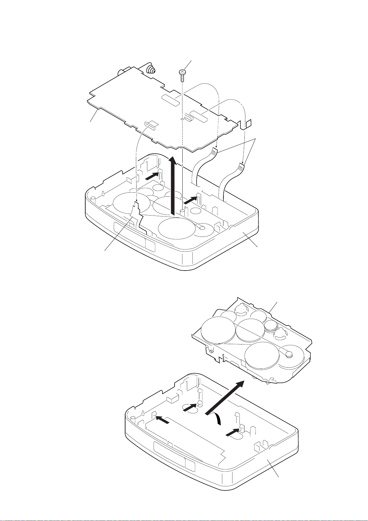
2-2. MAIN BOARD
Mechanism deck
Cabinet (front) assy
2
1
1
1
MAIN board
4
1
Screw (1.7 × 2.5), tapping
5
4
3
PC board, flexible
HEAD flexible board
2-3. MECHANISM DECK
• Use caution when installing the cassette holder assy
Install the cassette holder with the spring (lid up) as shown
below in the drawing so that it fits into the holes on the
cabinet front assy. Once installed, f it the left and right pieces
on.
Cabinet (front) assy
— 6 —
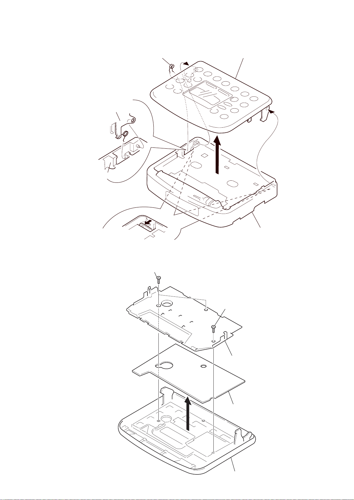
2-4. CASSETTE LID SUB ASSY
y
Cassette lid sub assy
Cabinet (front) assy
• Press on the left & right clips from the
rear of the Cabinet (front) assy, and
remove the boss.
3
Spring (lid up)
1
Cassette lid sub assy
2
2-5. DISPLAY BOARD
1
Screws
1
Screws
Holder
Cabinet (front) ass
2
— 7 —
DISPLAY board
Cassette lid
SECTION 3
r
MECHANICAL ADJUSTMENT
SECTION 4
ELECTRICAL ADJUSTMENT
PRECAUTION
1. Clean the following parts with a denatured-alcahol-moistened
sweb :
Playback head Pinch roller
Rubber belt Capstan
2. Demagnetize the playback head using a demagnetizer.
3. Do not use a magnetized screwdriver for adjustments.
4. After adjusting, apply screw-locking compound onto the
adjusted parts.
5. Unless specified otherwise, use a specified voltage (3.0V) to
perform the adjustments.
Torque Measurement
Mode
FWD
FWD
Back Tension
REV
REV
Back Tension
FF
REW
Torque meter
CQ-102C
CQ-102RC
CQ-201B
Meter reading
20 - 42 g · cm
(0.28-0.58 oz · inch)
Less than 2 g · cm
(Less than 0.03 oz · inch)
20 - 42 g · cm
(0.28-0.58 oz · inch)
Less than 2 g · cm
(Less than 0.03 oz · inch)
More than 50 g · cm
(More than 0.69 oz · inch)
PRECAUTION
1. Specified voltage : 3.0V
2. Switch and control position
MENU switch
MENU → TAPE → SET : NORM
MENU → SOUND → SET : No message
MENU → AVLS → SET : No message
MENU → aNR → SET : OFF (FX485/FX487)
VOL control : maximum
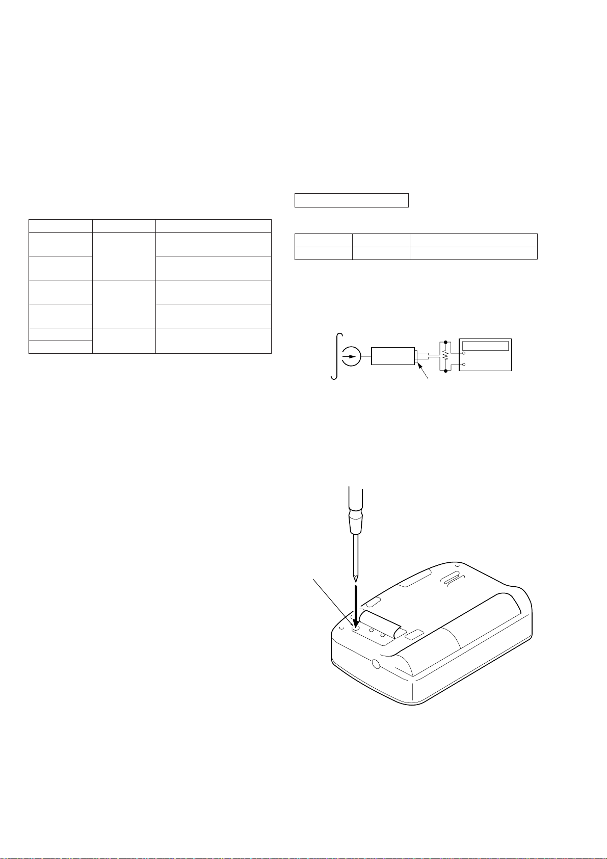
CASSETTE SECTION
T est Tape
Type
WS-48A
Tape Speed Adjustmnet
Procedure :
Test tape
WS-48A
(3kHz, 0dB)
Signal
3kHz, 0dB
Set
Tape Speed Adjustment
Ω
16
Purpose
Frequency counte
+
–
PHONES jack
1. Playback WS-48A (T ape center part) and adjust RV601 so that
the frequency counter reading becomes 2,985Hz to 3,015Hz.
2. Playback WS-48A (Tape top and end).
Check that frequency counter reading is within 1.5% of the
reading of step1.
Adjustment Point :
RV601
— 8 —
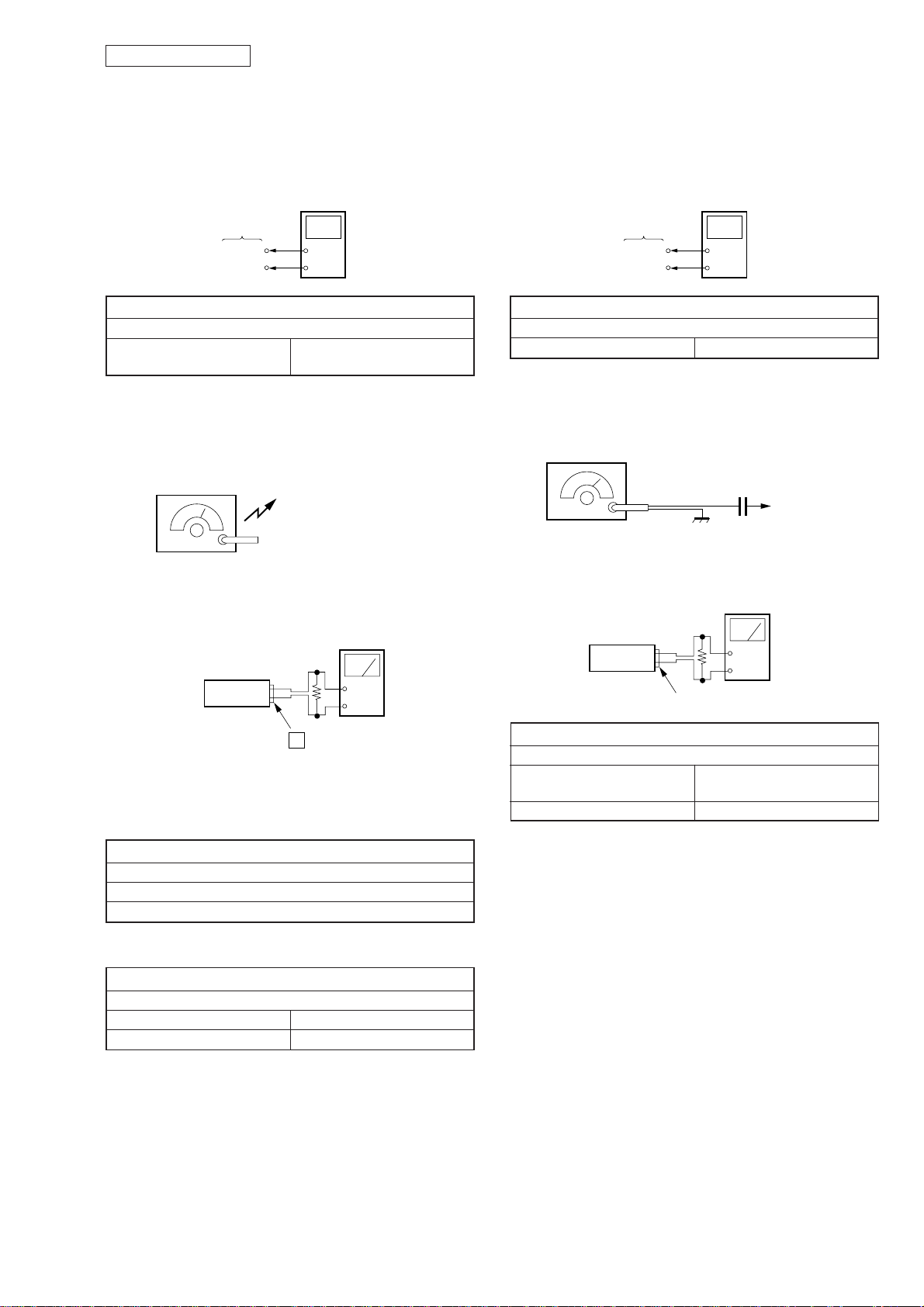
TUNER SECTION
Set
PHONES
+
–
FM RF signal
generator
75kHz frequency
deviation by 1KHz signal.
Output level : as low as possible.
0.01µF
to IC1 pin
1
Level meter
(AC : 0.5 – 5V range)
16
Ω
)
r
r
[AM]
Setting :
RADIO ON/BAND switch : ON/AM
AM T uning Volta ge Adjustment
digital voltmete
MAIN board
(VT)
(GND)
+
–
AM TUNING VOL T A GE ADJUSTMENT
Adjust for a 1.5 ± 0.03Vde reading on digital voltmeter.
L3
530kHz
(531kHz)
( ) : Except US, Canadian models
AM IF Adjustment, AM Tracking Adjustment
AM RF signal
generator
Put the lead-wire antenna
close to the set.
[FM]
Setting :
RADIO ON/BAND switch : ON/FM
FM T uning V oltage Adjustment
digital voltmete
MAIN board
(VT)
(GND)
+
–
FM TUNING VOL T A GE ADJUSTMENT
Adjust for a 10.0 ± 0.03Vde reading on digital voltmeter.
L2 108MHz
FM T racking Adjustment
30% amplitude modulation
by 400Hz signal.
Output level : as low as possible
• Repeat the procedures in each adjustment several times, and the
frequency coverage and tracking adjustments should be finally
done by the trimmer capacitors.
Adjust for a maximum reading on level meter.
( ) : Except US, Canadian models
Adjust for a maximum reading on level meter.
( ) : Except US, Canadian models
Level meter
(AC : 0.5 – 5V range
16
Ω
Set
2
+
–
jack
AM IF ADJUSTMENT
T1
1,000 (999) kHz
AM TRACKING ADJUSTMENT
L4 620kHz (621kHz)
CT2 1,400kHz (1,395kHz)
FM TRACKING ADJUSTMENT
Adjust for a maximum reading on level meter.
L1
CT1 108MHz
[ ] : East European model
87.5MHz
[65.0MHz]
— 9 —
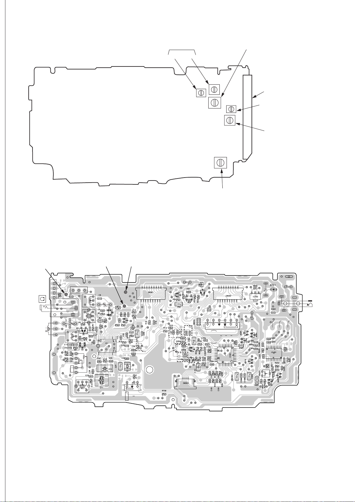
T
[MAIN BOARD] — SIDE A —
FM TRACKING ADJUSTMENT
CT1 L1
AM TUNING VOLTAGE ADJUSTMENT
L3
AM TRACKING ADJUSTMENT
L4 (FERRITE BAR ANTENNA)
AM TRACKING ADJUSTMEN
CT2
FM TUNING VOLTAGE
ADJUSTMENT
L2
AM IF ADJUSTMENT
T1
[MAIN BOARD] — SIDE B —
TP
(ANT)
J301
VCC
DATAREMO
GND
L4
TP(ANT)
L2
FL1
RV301
VOL
1
3
L1
L3
CT2
R
L
T1
TP
(VT)
TP
(GND)
C34
2
TP(GND)
CT1
R6
R19
C16
R18R21
TP(VT)
R20
S701
C17
Q4
HOLD
OFF
1
ON
EXCEPT
US,CND,C&SA
18
17
FX485/
FX487
MODELS
FX483
MODEL
C205
C105
FX485/
FX487
FX483
C36
MODELS
1
MODEL
C37
6
S601
MD
CONTROL
2
1
RVS
REW
18
17
FF
FWD
C701
1
3
C306
C606
— 10 —
 Loading...