

Sony WMFX-477, WMFX-479 Service manual
WM-FX477/FX479
SERVICE MANUAL
Ver 1.0 1999. 02
Photo: WM-FX477
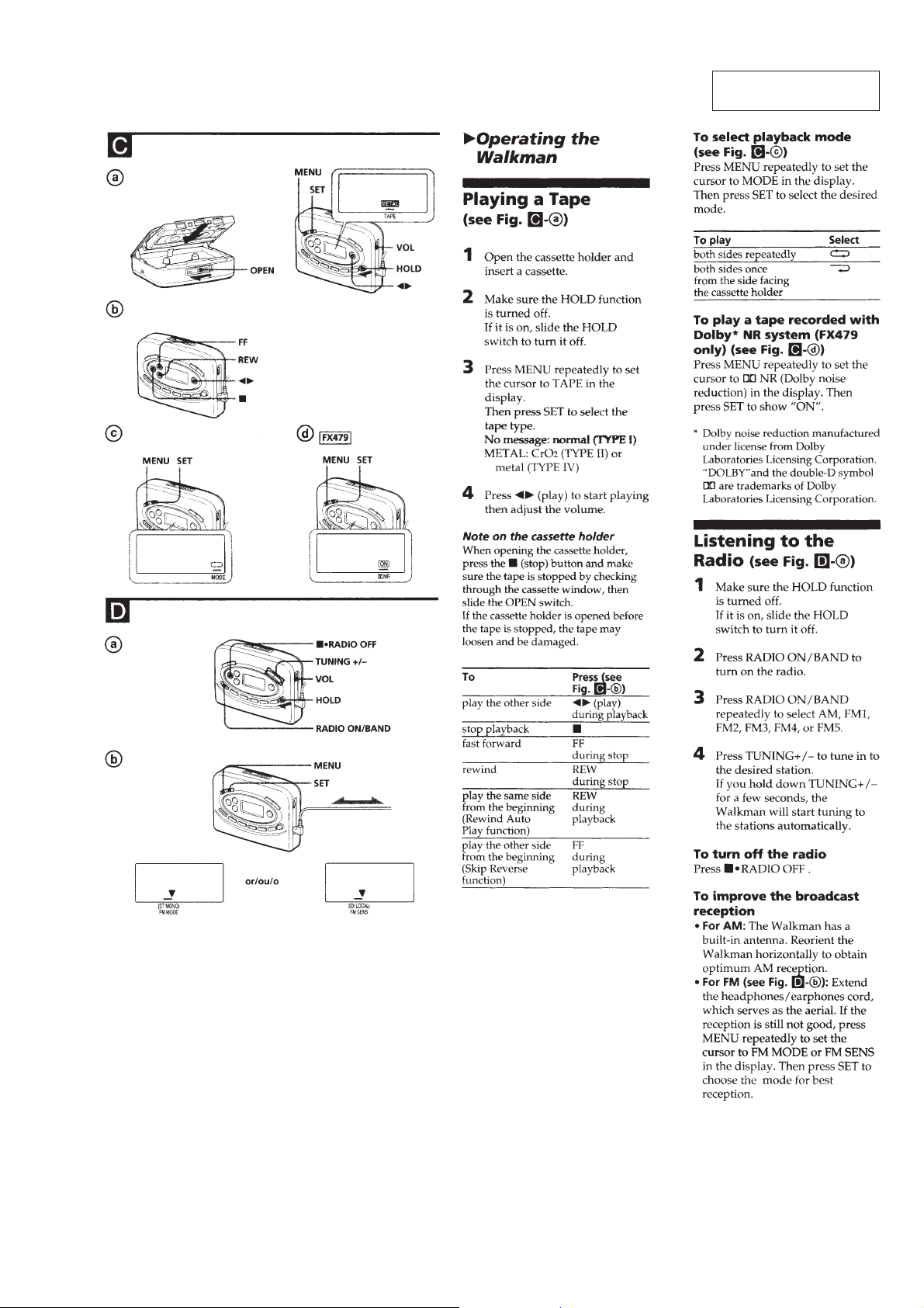
Dolby noise reduction manufactured under license from Dolby Laboratories Licensing Corporation.
“DOLBY” and the double-D symbol a are trademarks of Dolby
Laboratories Licensing Corporation.
SPECIFICATIONS
Radio section
US Model
Canadian Model
AEP Model
E Model
Chinese Model
Model Name Using Similar Mechanism WM-FX483
Tape Transport Mechanism Type MF-WMFX483-147
Frequency range
FM: 65 – 74/87.5 – 108 MHz (East
European)
87.5 – 108 MHz (Except East European)
AM:530 – 1,710 kHz (US, Canadian)
531 – 1,602 kHz (Except US, Canadian)
Tape section
Frequency response
(Dolby NR off)
Playback: 30 – 14,000 Hz
Output
Headphones/earphones (2 jack)
Load impedance 8 – 300 ohms
General
Power requirements
3 V DC batteries R6 (AA) × 2/
External DC 3 V power sources
Dimensions (w/h/d)
Approx. 115.8 × 85 × 33.4 mm
(4 5/8 × 3 3/8 × 1 3/8 inches) incl.
projecting parts and controls
Mass
Approx. 175 g (6.2 oz.)/Approx.
255 g (9.0 oz.) incl.batteries and a
cassette
Supplied accessories
Stereo headphones or Stereo
earphones (1)
Carrying case (1)
Design and specifications are subject to change without
notice.
Notes on Chip Component Replacement
• Never reuse a disconnected chip component.
• Notice that the minus side of a tantalum capacitor may be dam-
aged by heat.
RADIO CASSETTE PLAYER
MICROFILM
– 1 –

TABLE OF CONTENTS
1. GENERAL ........................................................................... 3
2. DISASSEMBLY
2-1. Cabinet (Front) Assy ........................................................... 5
2-2. Display Board ..................................................................... 6
2-3. Holder (Sub) Assy, Cassette ................................................ 6
2-4. Main Board ......................................................................... 7
2-5. Mechanism Deck................................................................. 7
2-6. Belt and Motor .................................................................... 8
3. MECHANICAL ADJUSTMENTS................................. 9
4. ELECTRICAL ADJUSTMENTS
Tape Section ............................................................................ 9
Tuner Section......................................................................... 10
5. DIAGRAMS
5-1. IC Pin Description............................................................. 12
5-2. Block Diagram .................................................................. 14
5-3. Schematic Diagram –Main Section–................................. 16
5-4. Printed Wiring Board –Main Section–.............................. 19
5-5. Printed Wiring Board –Display Section– ..........................21
5-6. Schematic Diagram –Display Section–............................. 23
6. EXPLODED VIEWS
6-1. Cabinet Section ................................................................. 26
6-2. Tape Mechanism Deck Section ......................................... 28
7. ELECTRICAL PARTS LIST......................................... 29
– 2 –
SECTION 1
GENERAL
This section is extracted
from instruction manual.
– 3 –
– 4 –
A
cabinet (front) assy
2
screw (1.7x2.5), tapping
1
screw (1.7x2.5), tapping
holder (sub) assy, cassette
Cabinet (front) assySet Main board
Holder (sub) assy, cassette
Belt and MotorMechanism deckDisplay board
SECTION 2
DISASSEMBLY
• The equipment can be removed using the following procedure.
Note : Follow the disassembly procedure in the n umerical order given.
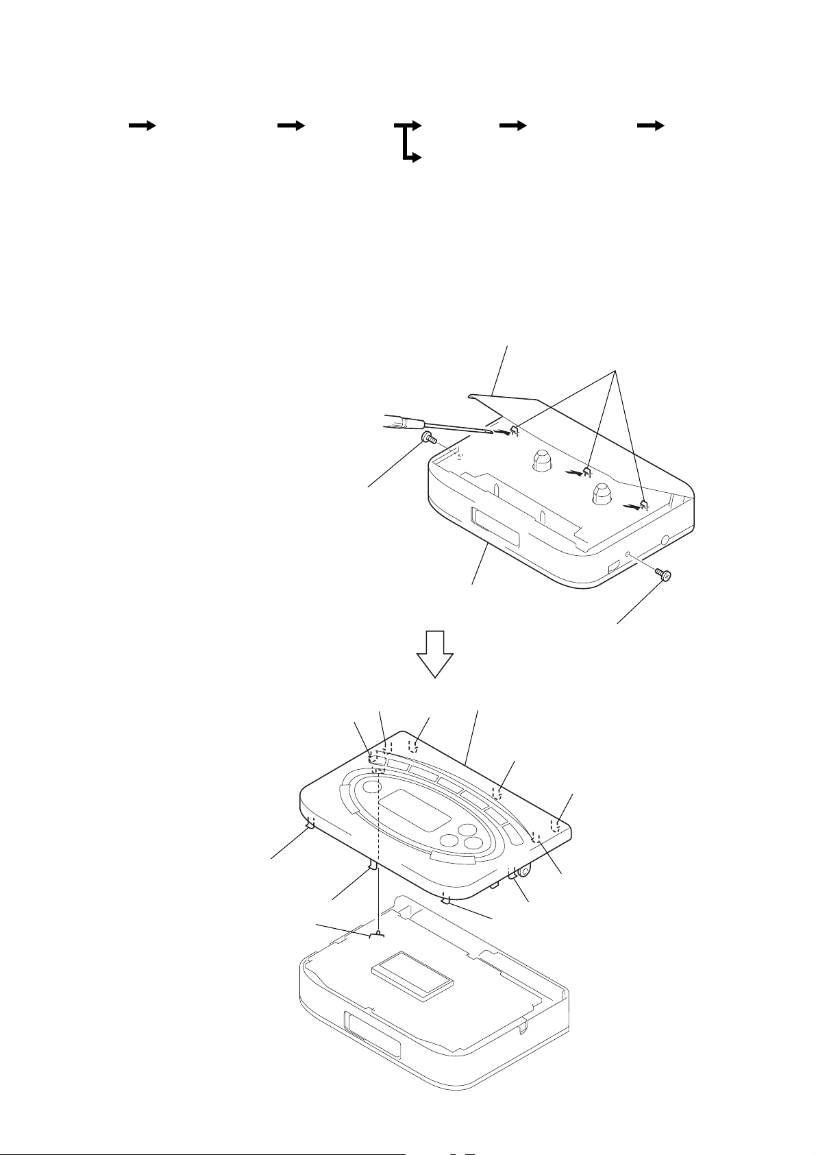
2-1. CABINET (FRONT) ASSY
Note : When installing, fit the knobs and s witches.
3
Insert the precision screwdriver
(1.4 mm flat-blade) into the slit
at claw A and release the claw.
4
Remove the cabinet (front) assy.
(Release all claws B to K in
alphabetical order.)
Note :When removing the cabinet, put cloth
on the end of a screwdriver or use a
polyacetal driver to avoid damage to
the cabinet.
C
S701
B
D
E
cabinet (front) assy
F
G
H
I
J
K
– 5 –
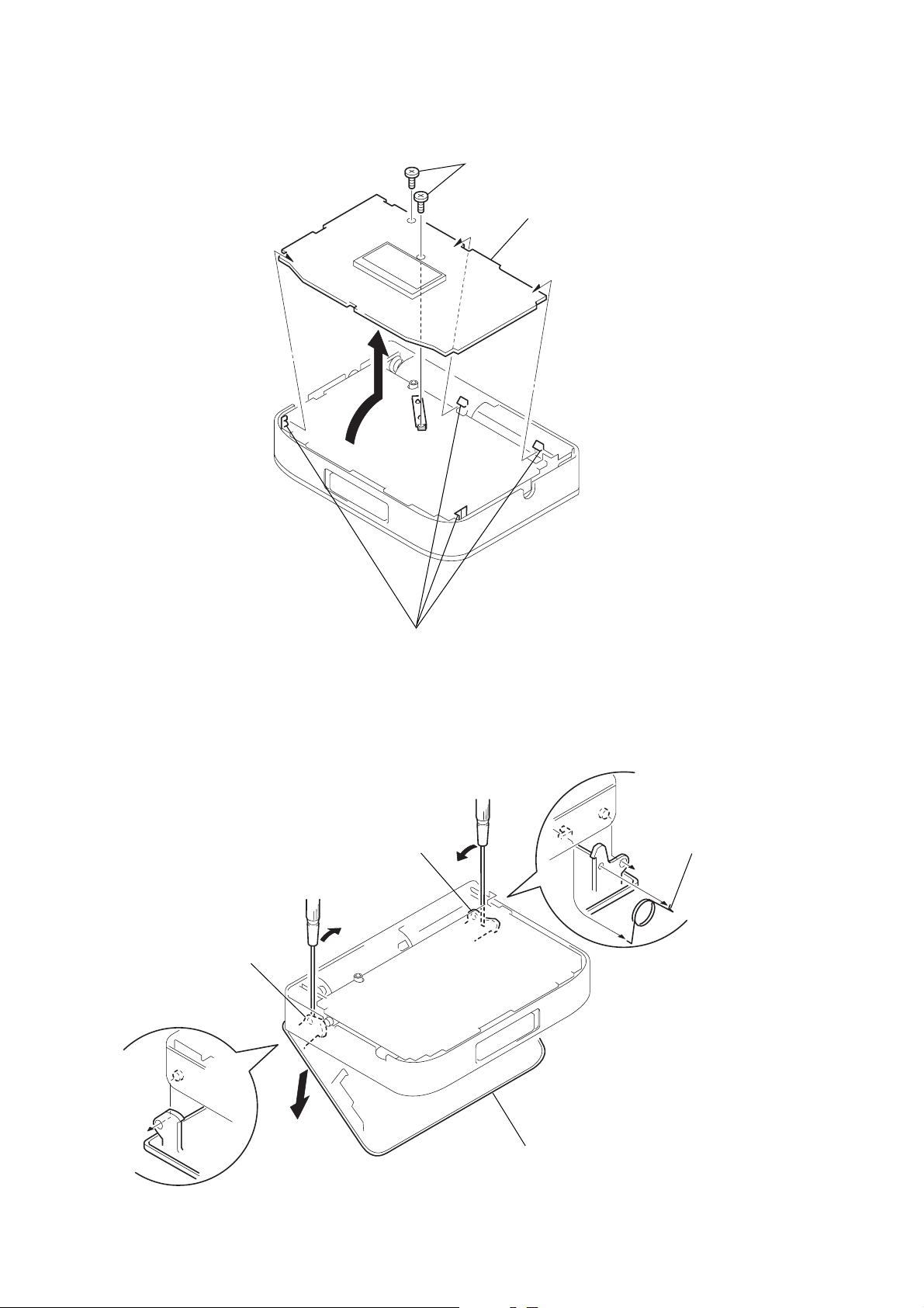
2-2. DISPLAY BOARD
1
screws
3
DISPLAY board
2-3. HOLDER (SUB) ASSY, CASSETTE
2
Insert a precision screwdriver
(1.4 mm flat-blade) vertically
into portion A to release the
hinge plate.
3
Portion B to release the
hinge plate.
A
2
four claws
B
5
spring (torsion)
– 6 –
1
Open the holder (sub) assy, cassette.
4
holder (sub) assy, cassette
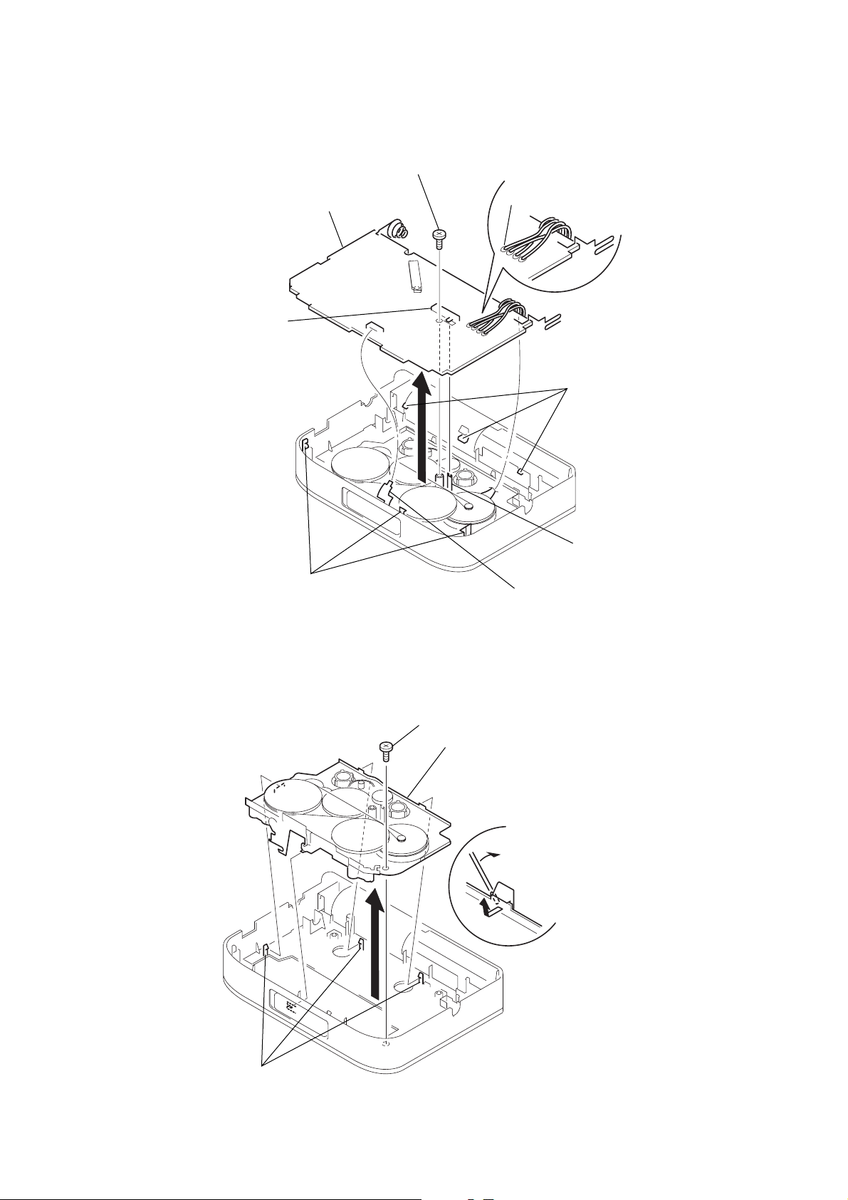
5
three claws
4
three claws
1
HEAD FLEXIBLE board (CN303)
2
Unsolder the 4 places.
3
screw (M1.4x2.0), locking
6
MAIN board
switch
slider
2-4. MAIN BOARD
Note : When installing, fit the s witch and slider.
2-5. MECHANISM DECK
1
screw
4
Remove the mechanism deck
in the direction of the arrow.
2
Insert the precision screwdriver
(1.4 mm flat-blade) into the slit
and release three claws.
3
three claws
– 7 –
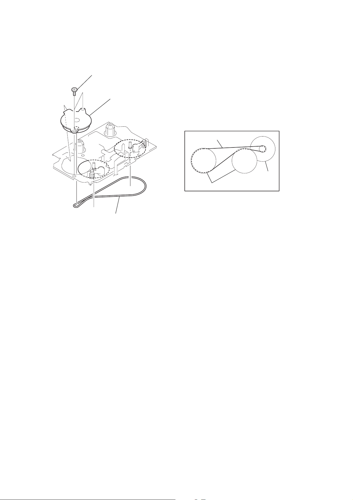
2-6. BELT AND MOTOR
2
two screws (screw (M1.4), special head)
3
motor
1
belt
• How to apply the belt
belt
M901
wheel assy (SP), capstan
– 8 –
 Loading...