

Sony WM-FX277, WM-FX467, WM-FX467ST Service manual
WM-FX277/FX467/FX467ST
SERVICE MANUAL
Ver 1.0 2000.03
Photo : WM-FX467
SPECIFICATIONS
US Model
Model Name Using
Mechanism T ype
Similar Mechanism WM-FX277 : MF-WMFX277-114
T ape Transport WM-FX467/FX467ST: MF-WMFX467-114
NEW
• Frequency range
FM: 87.5 - 108 MHz
AM: 530 - 1,710 kHz
TV: 2 - 13 ch
• Power requirements
3V DC batteries R6 (AA) x 2
• Dimensions (w/h/d)
Approx. 91.4 x 115.5 x 35.0 mm (3 5⁄8 x 4 5⁄8 x 1 7⁄16 inches)
incl. projecting parts and controls
• Mass
FX467/FX467ST: Approx. 155 g (5.5 oz)/Approx. 235 g (8.3 oz) incl.
batteries and a cassette
FX277: Approx. 145 g (5.2 oz)/Approx. 225 g (8.0 oz) incl. batteries
and a cassette
• Supplied accessories
Stereo headphones or Stereo earphones (1)
Carrying case with belt clip(1)
Design and specifications are subject to change without notice.
Battery life (approximate hours) (EIAJ*)
Sony alkaline LR6 (SG) Sony R6P (SR)
Tape playback 25 7.5
Radio reception 40 14
* Measured value by the standard of EIAJ (Electronic Industries
Association of Japan). (Using a Sony HF series cassette tape)
Note
• The battery life may shorten depending on the operation of the unit.
RADIO CASSETTE PLAYER
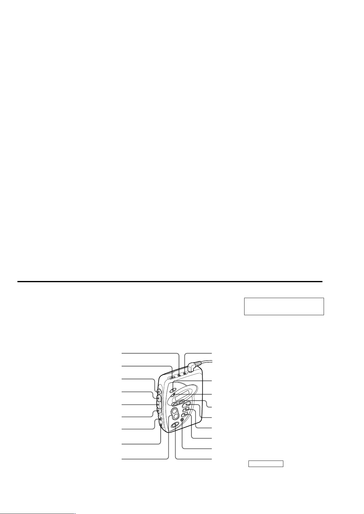
TABLE OF CONTENTS
Specifications ........................................................................... 1
1. GENERAL
Location and Function of Controls .................................... 2
Flexible Circuit Board Repairing
• Keep the temperature of the soldering iron around 270°C during
repairing.
• Do not touch the soldering iron on the same conductor of the
circuit board (within 3 times).
• Be careful not to apply force on the conductor when soldering or
unsoldering.
2. DISASSEMBLY
2-1. Cabinet (Front) ........................................................... 3
2-2. Main Board ................................................................. 3
2-3. Mechanism Deck ........................................................ 4
2-4. Belt, Capstan/Reel Motor (M601) .............................. 4
2-5. Cassette Holder........................................................... 5
3. ADJUSTMENTS
3-1. Mechanical Adjustments............................................. 6
3-2. Electrical Adjustments................................................ 6
4. DIAGRAMS
4-1. Explanation of IC Terminals....................................... 9
4-2. Block Diagram.......................................................... 10
4-3. Printed Wiring Boards .............................................. 13
4-4. Schematic Diagram................................................... 17
5. EXPLODED VIEWS
5-1. Cabinet Section......................................................... 21
5-2. Mechanism Deck Section (WM-FX277).................. 22
5-3. Mechanism Deck Section
(WM-FX467/FX467ST) ........................................... 23
6. ELECTRICAL PARTS LIST................................... 24
Notes on chip component replacement
• Never reuse a disconnected chip component.
• Notice that the minus side of a tantalum capacitor may be damaged by heat.
LOCATION AND FUNCTION OF CONTROLS
AVLS
NORM • LIMIT
VOLUME
x STOP
M
N PLAY
m
(FX467 / FX467ST only)
(FX467 / FX467ST only)
DIR • Y
MODE • s / d
PRESET +
SECTION 1
GENERAL
NORM • CrO2 / METAL
DX • LOCAL
i
MEGA BASS
ENTER
TUNING + / -
TV
FM
AM
OFF
HOLD
This section is extracted from
instruction manual.
FX467 / FX467ST
– 2 –
SECTION 2
Y
Y
DISASSEMBLY
z
The equipment can be removed using the following procedure.
Set
Main boardCabinet (Front)
Cassette holder
Note : Follow the disassembly procedure in the numerical order given.
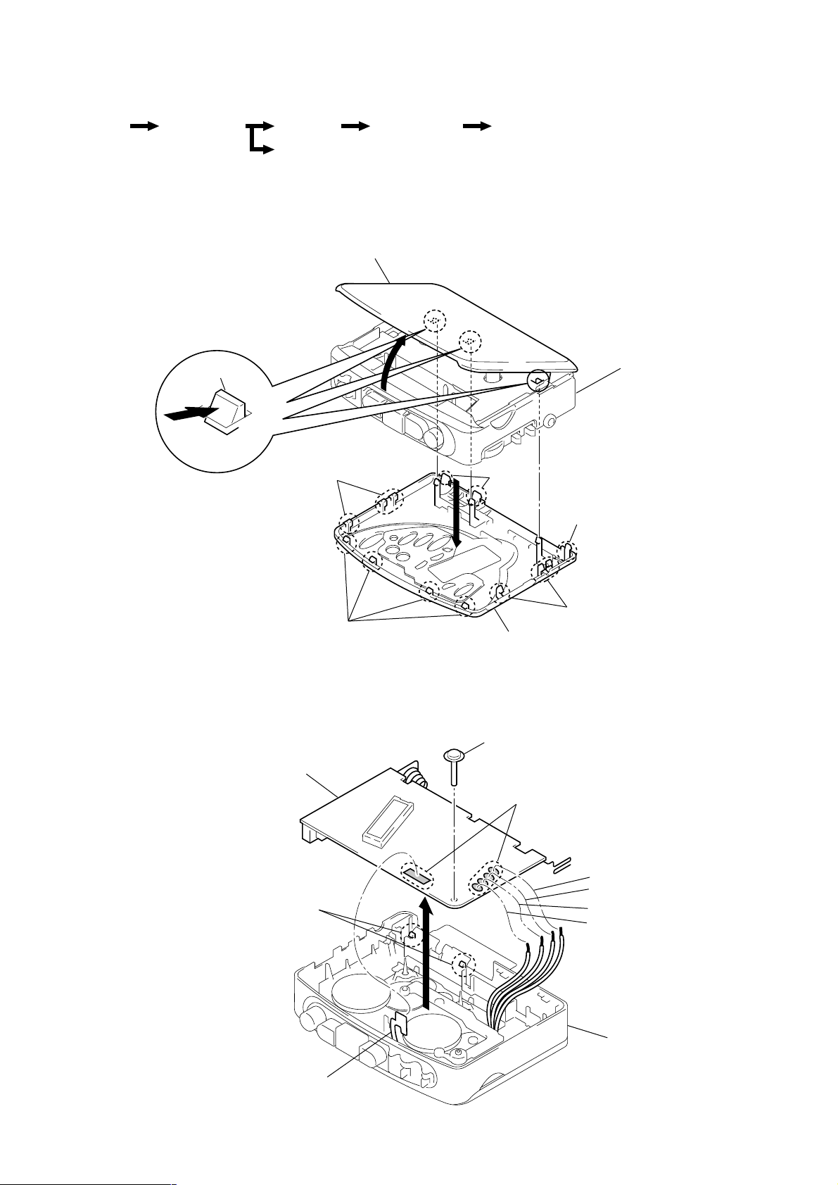
2-1. CABINET (FRONT)
Mechanism deck Belt, Capstan/reel motor (M601)
Cassette holder
3 Claws
2-2. MAIN BOARD
1 Claws
1 Claws
2
5
Cabinet (center) sub ASS
4 Claw
4 Claw
1 Claws
Cabinet (Front)
1 Screw
Main board
3 Claws
Head flexible board
4
– 3 –
2 Remove solder
Orange
Black
White
Red
Cabinet (center) sub ASS
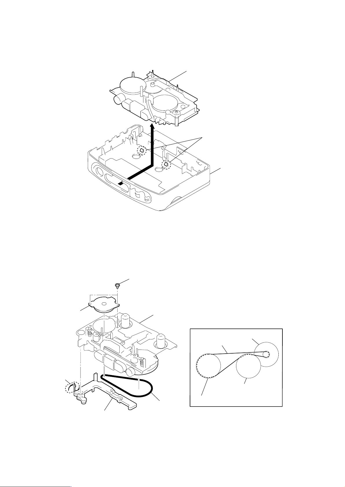
2-3. MECHANISM DECK
Y
2 Belt
Stopper
1 Claw
4 Capstan/reel motor
(M601)
wheel ASSY (P), capstan
(FX467/FX467ST)
wheel ASSY (P), capstan
Belt
• How to apply the belt
Capstan/reel motor
(M601)
3 Screws (M1.4)
Mechanism deck
Mechanism deck
1 Claws
2-4. BELT, CAPSTAN/REEL MOTOR (M601)
2
Cabinet (center) sub ASS
– 4 –
r
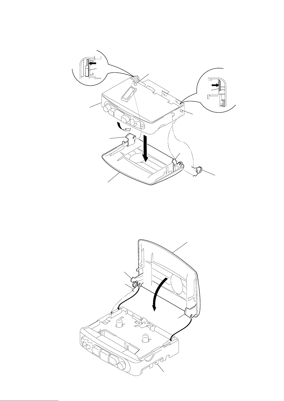
2-5. CASSETTE HOLDER
2 Move the hinge away
from projection
Cabinet (center)
sub ASSY
Cassette holder
Hinge
Hinge
1
Projection
5
3 Move the hinge away
from projection
Hinge
Projection
Hinge
4 Spring (torsion)
z
CAUTIONS DURING ASSEMBLY
1 Insert the spring (torsion) to the L shape slot as shown in the figure.
2,3 Insert the hinge of the “Cassette holder ”.
4 Close the “Cassette holder” then press it.
Hinge
Spring (torsion)
4
1
2
Cassette holde
Hinge
3
– 5 –
Cabinet (center) sub ASSY
 Loading...