

Sony WMFX-271, WMFX-275 Service manual
WM-FX271/FX275
SERVICE MANUAL
Ver 1.0 1999. 02
Photo: WM-FX271
SPECIFICATIONS
Frequency range
FM: 65 – 74/87.5 – 108 MHz (East European)
87.5 – 108 MHz (Except East European)
AM:530 – 1,710 kHz (US, Canadian)
531 – 1,602 kHz (Except US, Canadian)
Power requirements
3 V DC batteries R6 (AA) × 2/External DC 3 V power sources
Dimensions
91.4 × 115.5 × 35.9 mm (3 5/8 × 4 5/8 × 1 7/16 inches) (w/h/d) incl.
projecting parts and controls
Mass
Approx. 150 g (5.3 oz.)
Approx. 230 g (8.2 oz.) incl.batteries and a tape
Supplied accessories
Stereo headphones or Stereo earphones (1)/Carrying case (1)
Design and specifications are subject to change without
notice.
US Model
WM-FX271/FX275
Canadian Model
AEP Model
E Model
Chinese Model
WM-FX271
Model Name Using Similar Mechanism WM-FX171
Tape Transport Mechanism Type MF-WMFX171-114
MICROFILM
Notes on Chip Component Replacement
• Never reuse a disconnected chip component.
• Notice that the minus side of a tantalum capacitor may be dam-
aged by heat.
Flexible Circuit Board Repairing
• Keep the temperature of the soldering iron around 270˚C during
repairing.
• Do not touch the soldering iron on the same conductor of the
circuit board (within 3 times).
• Be careful not to apply force on the conductor when soldering
or unsoldering.
RADIO CASSETTE PLAYER
– 1 –

TABLE OF CONTENTS
1. GENERAL ........................................................................... 3
2. DISASSEMBLY
2-1. Cabinet (Front) Sub Assy....................................................4
2-2. Main Board ......................................................................... 5
2-3. Holder (Sub) Assy, Cassette ................................................ 5
2-4. Mechanism Deck................................................................. 6
2-5. Belt and Motor .................................................................... 6
3. MECHANICAL ADJUSTMENTS.................................7
4. ELECTRICAL ADJUSTMENTS
Tape Section ............................................................................ 7
Tuner Section........................................................................... 8
5. DIAGRAMS
5-1. IC Pin Description.............................................................10
5-2. Block Diagram .................................................................. 11
5-3. Printed Wiring Board ........................................................ 13
5-4. Schematic Diagram ........................................................... 15
6. EXPLODED VIEWS
6-1. Cabinet Section .................................................................18
6-2. Tape Mechanism Section-1 ............................................... 19
6-3. Tape Mechanism Section-2 ............................................... 20
7. ELECTRICAL PARTS LIST ........................................ 21
– 2 –
SECTION 1
GENERAL
This section is extracted
from instruction manual.
– 3 –
SECTION 2
6
DISASSEMBLY
• The equipment can be removed using the following procedure.
Cabinet (front) sub assy Main boardSet Holder (sub) assy, cassette Belt and Motor
Mechanism deck
Note : Follow the disassemb ly procedure in the numerical order given.
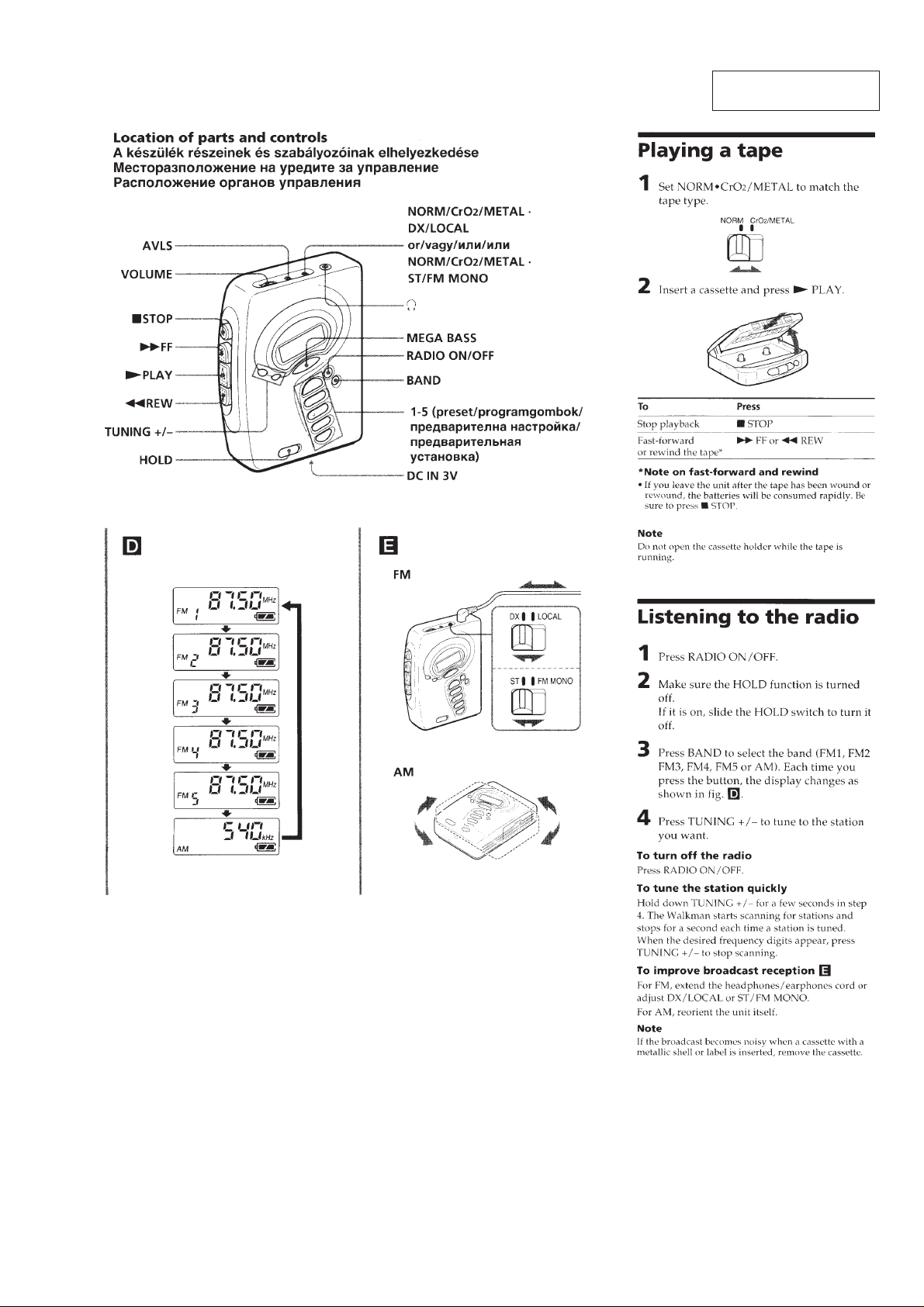
2-1. CABINET (FRONT) SUB ASSY
Note : When installing, fit the knobs and s witches .
1
Insert the precision screwdriver
(1.4 mm flat-blade) into the slit
at claw A and release the claw.
2
Remove the cabinet (front) sub assy.
(Release all claws B to N in
alphabetical order.)
A
holder (sub) assy, cassette
cabinet (front) sub assy
cabinet (front) sub assy
E
D
C
B
F
G
Note :When removing the cabinet, put cloth
on the end of a screwdriver or use a
polyacetal driver to avoid damage to
the cabinet.
H
I
J
K
L
M
N
S71
– 4 –
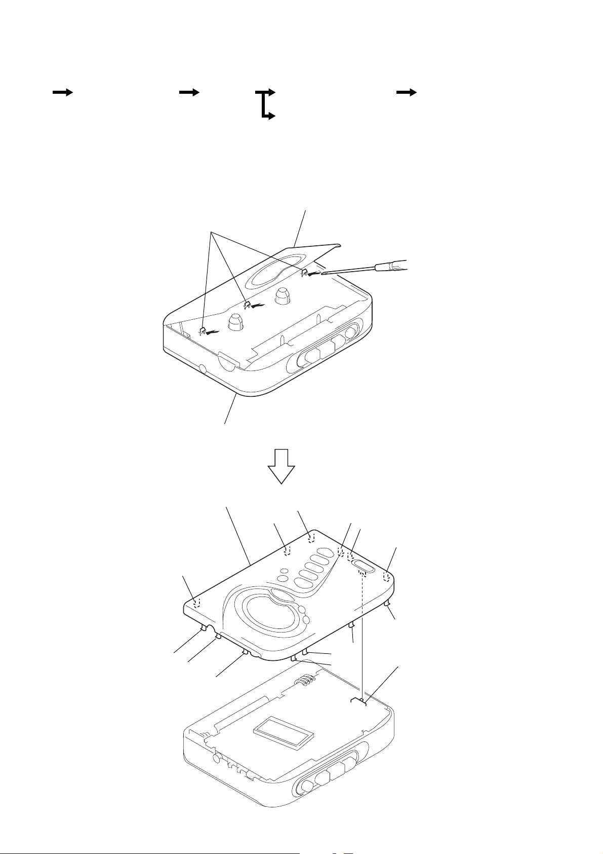
2-2. MAIN BOARD
)
2
Unsolder the 4 places.
5
MAIN board
3
screw (M1.4), toothed lock (WH)
4
two claws
2-3. HOLDER (SUB) ASSY, CASSETTE
2
Insert a precision screwdriver
(1.4 mm flat-blade) vertically
into portion A to release the
hinge plate.
3
Portion B to release the
hinge plate.
A
B
1
HEAD FLEXIBLE board (CN301)
spring (torsion
5
– 5 –
1
Open the holder (sub) assy, cassette.
4
holder (sub) assy, cassette.
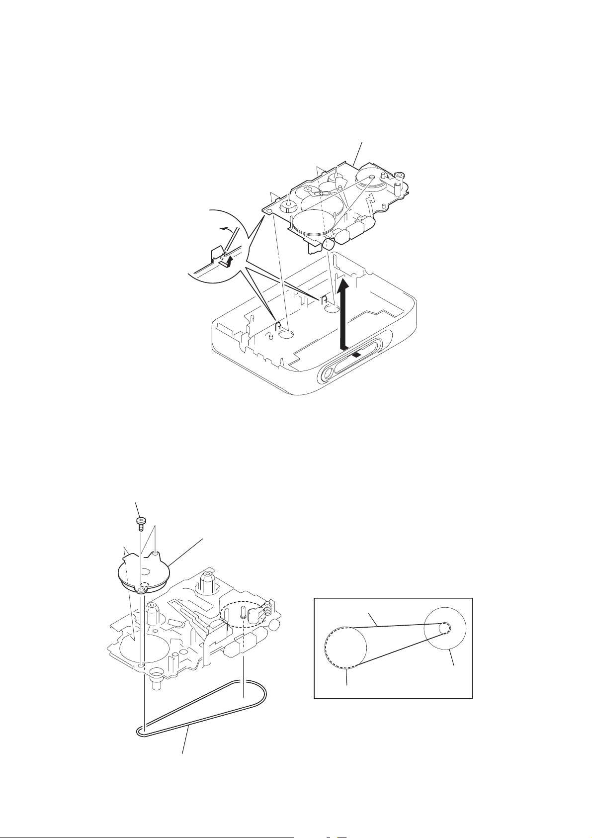
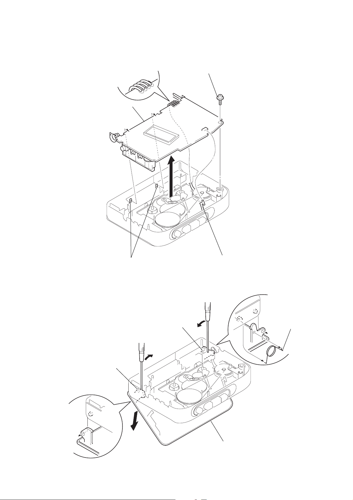
2-4. MECHANISM DECK
1
Insert the precision screwdriver
(1.4 mm flat-blade) into the slit
and release three claws.
2
Remove the mechanism deck
in the direction of the arrow.
2-5. BELT AND MOTOR
2
two screws (screw (M1.4), special head)
3
motor
• How to apply the belt
belt
M901
wheel assy (NP), capstan
1
belt
– 6 –
SECTION 3
MECHANICAL ADJUSTMENTS
SECTION 4
ELECTRICAL ADJUSTMENTS
PRECAUTION
1. Clean the following parts with a denatured-alcohol-moistened
swab :
playback head pinch lever assy
capstan wheel assy rubber belt
2. Demagnetize the playback head with a head demagnetizer.
3. Do not use a magnetized screwdriver for the adjustments.
4. After the adjustments, apply suitable locking compound to the
parts adjusted.
5. The adjustments should be performed with the rated power
supply voltage (2.5 V) unless otherwise noted.
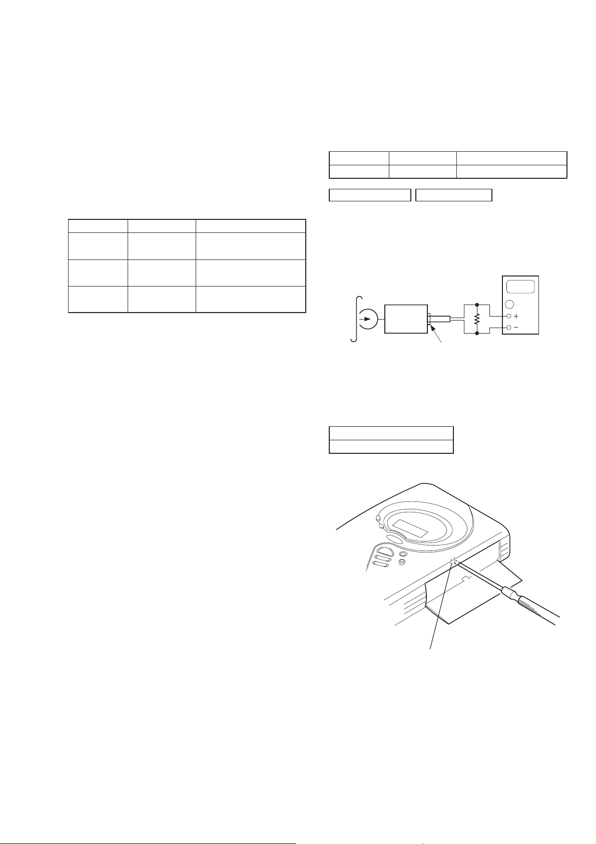
Torque Measurement
Mode Torque meter Meter reading
FWD CQ-102C
FWD
Back Tension (less than 0.03 oz • inch)
FF, REW CQ-201B
CQ-102C
20 – 42 g • cm
(0.28 – 0.58 oz • inch)
less than 2 g • cm
more than 60 g • cm
(more than 0.83 oz • inch)
PRECAUTION
• Supplied voltage : 2.5V
• Switch and control position
VOLUME control : maximum
AVLS switch : NORM
• Test Tape
Type Signal Used for
WS-48A 3 kHz, 0 dB tape speed adjustment
TAPE SECTION 0 dB = 0.775 V
T ape Speed Adjustment
Procedure:
test tape
WS-48A
(3 kHz, 0 dB)
set
2
jack (J301)
digital frequency
counter
Ω
16
0000
1. Playback WS-48A (tape center part) in the FWD state and
adjust RV601 so that the frequency counter reading
becomes 3,000 Hz.
Specification V alue:
Digital frequency counter
2,985 to 3,015 Hz
Adjustment Location:
RV601
– 7 –
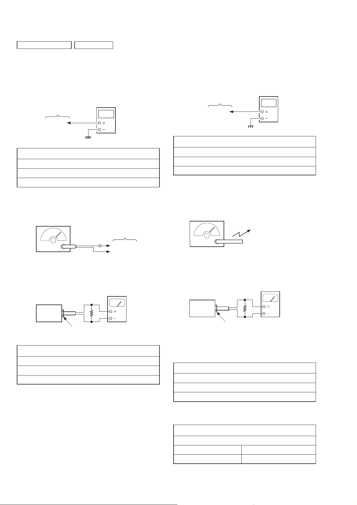
)
digital
voltmeter
TP (VT)
Main board
TUNER SECTION 0 dB = 1 µV
d
)
• FM Section
Setting:
RADIO ON/OFF switch: ON
BAND switch : FM
FM T uning V oltage Adjustment
digital
voltmeter
Main board
TP (VT)
FM TUNING VOLTA GE ADJUSTMENT
Adjust for a 8.5 ± 0.3 (14.5 ± 0.5) Vdc reading on digital voltmeter.
L3
108 MHz
FM T racking Adjustment
FM RF signal
generator
0.01 µF
Modulation: 1 kHz, 75 kHz dev. (100%)
Output level: as low as possible
Main boar
(FM RF IN)
(GND)
• AM Section
Setting:
RADIO ON/OFF switch: ON
BAND switch : AM
AM T uning Voltage Adjustment
AM TUNING VOL T AGE ADJUSTMENT
Adjust for a 1.1 ± 0.1 Vdc reading on digital voltmeter.
L4
530 (531) kHz
( ): Except US, Canadian model
AM IF Adjustment, AM Tracking Adjustment
AM RF signal
generator
Put the lead-wire
antenna close to
the set.
Modulation: 400Hz, 30%
Output level: as low as possible
Adjust for a maximum reading on level meter.
( ): East European model
level meter
(range: 0.5-5 V ac
16
Ω
set
2
jack (J301)
FM TRACKING ADJUSTMENT
L2
87.5 (65.0) MHz
level meter
(range: 0.5-5 V ac
16
Ω
set
2
jack (J301)
• Repeat the procedures in each adjustment several times, and the
tracking adjustment should be finally done by the trimmer capacitors.
AM IF ADJUSTMENT
Adjust for a maximum reading on level meter.
T1
1,000 (999) kHz
( ): Except US, Canadian model
AM TRACKING ADJUSTMENT
Adjust for a maximum reading on level meter.
L1 CT1
620 (621) kHz 1,400 (1,395) kHz
( ): Except US, Canadian model
– 8 –
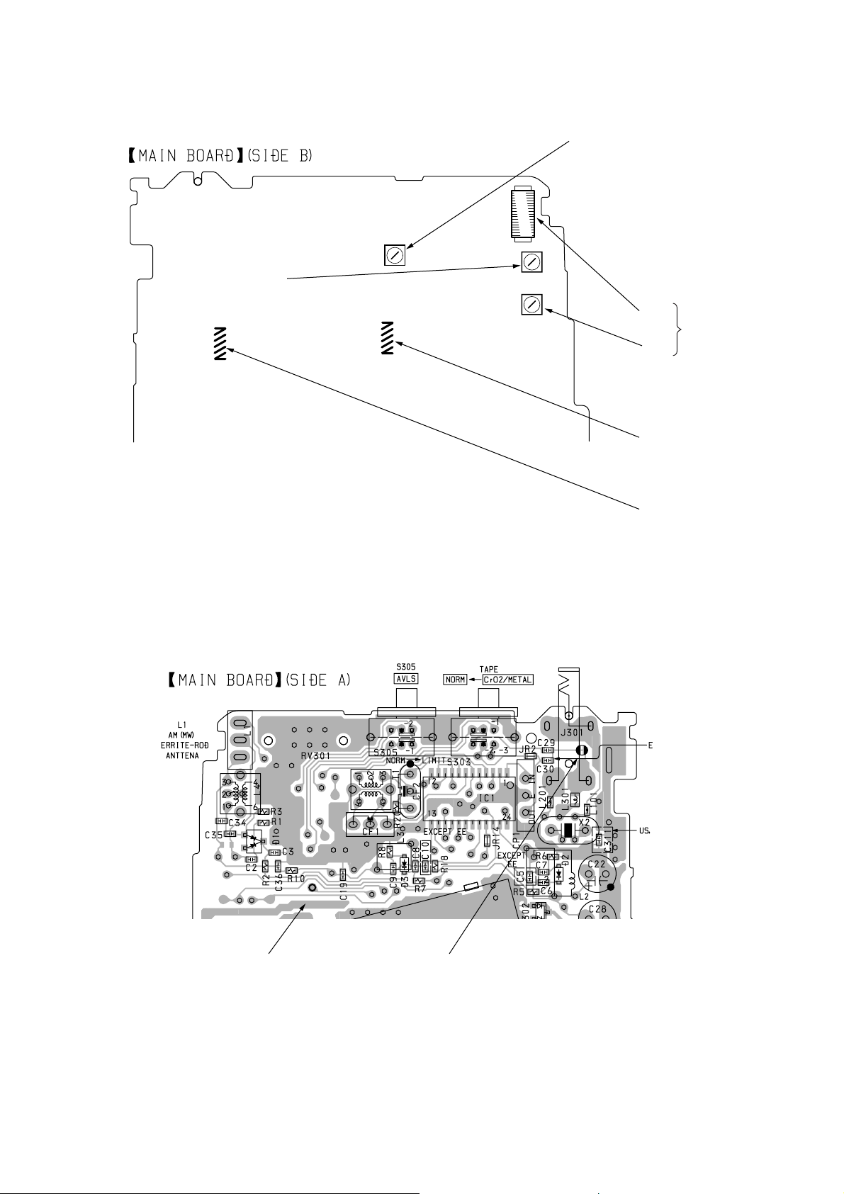
Adjustment Location: main board
L4
AM TUNING
VOLT AGE
ADJUSTMENT
T1
AM IF
ADJUSTMENT
L1
CT1
L3
FM TUNING
VOLT AGE
ADJUSTMENT
L2
FM TRACKING
ADJUSTMENT
AM TRACKING
ADJUSTMENT
Measurement Points: main board
(FM RF IN)
(VT)
FM RF INVT
– 9 –
 Loading...