

Sony WMFX-269 Service manual
WM-FX267/FX269
SERVICE MANUAL
Ver 1.3 2000. 05
With SUPPLEMENT-1
(9-923-300-81)
With SUPPLEMENT-2
(9-923-300-82)
Photo: WM-FX267 US model
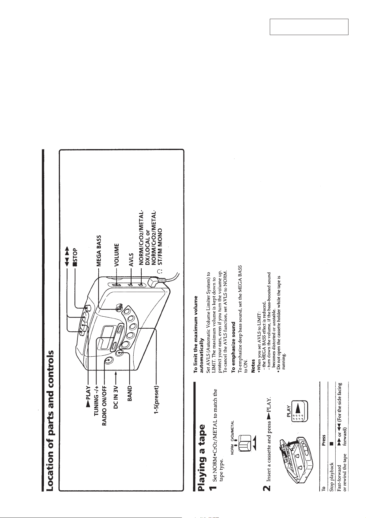
SPECIFICATIONS
• Frequency range
FM: 87.5-108MHz
AM: 530-1710kHz (US)
AM: 531-1602kHz (EXCEPT US)
• Power requirements
3V DC batteries AA (R6) × 2/External DC 3V
power sources
• Demensions
115 × 90.5 × 34.4mm (4 5/8 × 3 5/8 1 3/8 inches) (w/h/d)
incl. projecting parts and controls
• Mass
Approx. 150g (5.3 oz)
Approx. 230g (8.2 oz) incl. batteries and a tape
• Supplied accessories
Stereo headphones or earphones (1)
Carrying case (1)
US Model
WM-FX267/FX269
AEP Model
E Model
WM-FX267
Model Name Using Similar Mechanism WM-FX251
Tape Transport Mechanism Type MF-WMFX251-114
MICROFILM
Design and specifications are subject to change without notice.
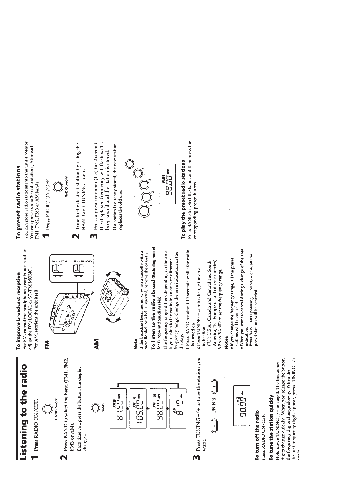
RADIO CASSETTE PLAYER
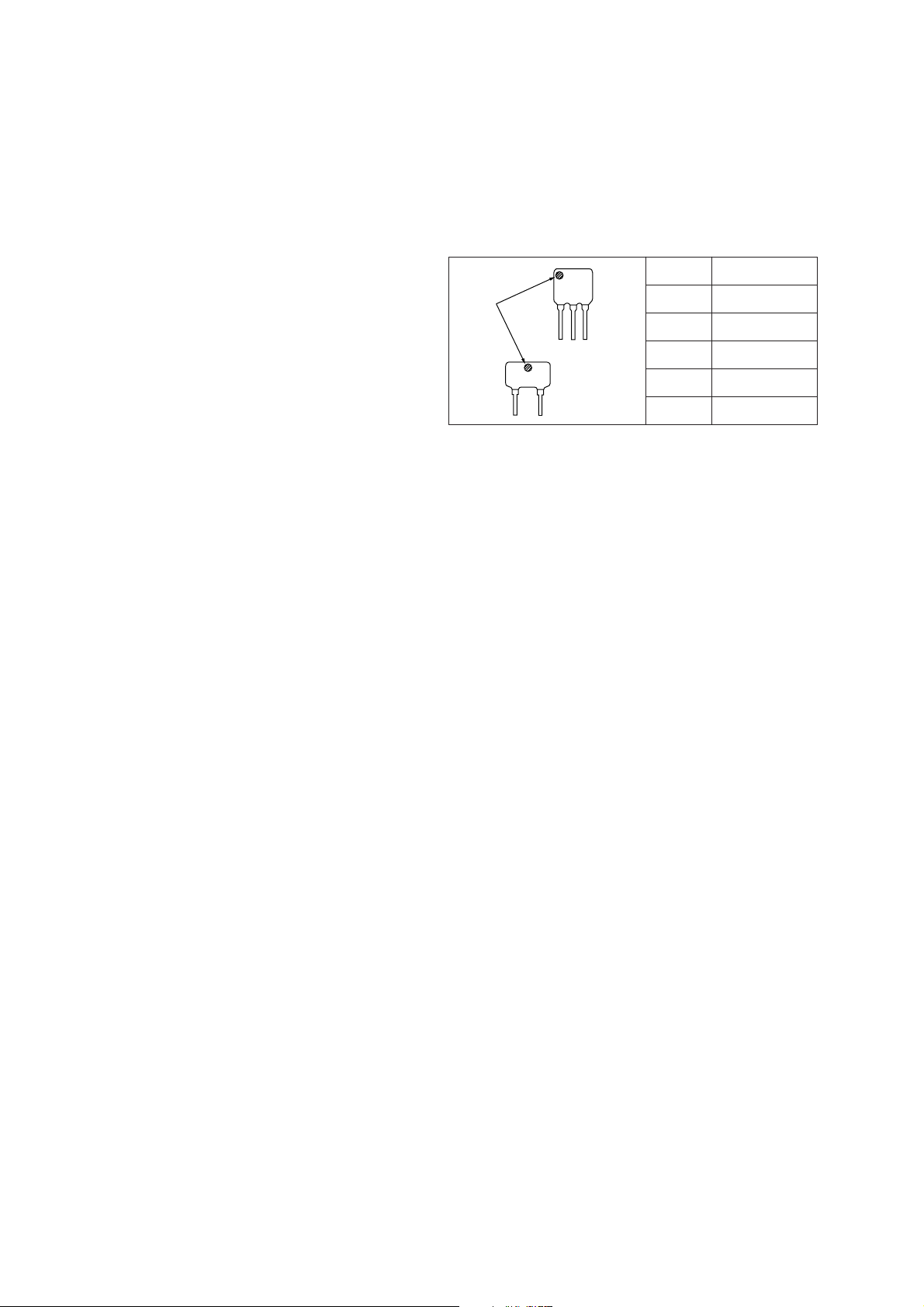
TABLE OF CONTENTS
SERVICING NOTES
1. GENERAL .................................................................. 3
2. DISASSEMBLY ........................................................ 6
3. MECHANICAL ADJUSTMENTS ...................... 9
4. ELECTRICAL ADJUSTMENTS
Tape Section .................................................................... 9
Tuner Section .................................................................. 10
5. DIAGRAMS
5-1. IC Pin Function Description ........................................... 12
5-2. Block Diagram ................................................................ 13
5-3. Printed Wiring Board ...................................................... 15
5-4. Schematic Diagram ......................................................... 19
6. EXPLODED VIEWS ................................................ 24
7. ELECTRICAL PARTS LIST ............................... 27
HOW TO CHANGE THE CERAMIC FILTERS
This model is used two ceramic filters of CF2 and X2.
You must used same type of color marked ceramic filters in order
to meet same specifications.
Therefore, the ceramic filter must changed two pieces together
since it's supply two pieces in one package as a spare parts.
CF2
mark
X2
Flexible Circuit Board Repairing
• Keep the temperature of the soldering iron around 270 ˚C dur-
ing repairing.
• Do not touch the soldering iron on the same conductor of the
circuit board (within 3 times).
• Be careful not to apply force on the conductor when soldering
or unsoldering
Notes on chip component replacement
• Never reuse a disconnected chip component.
• Notice that the minus side of a tantalum capacitor may be dam-
aged by heat.
Mark Center frequency
red 10.70MHz
blue 10.67MHz
orange 10.73MHz
black 10.64MHz
white 10.76MHz
– 2 –
SECTION 1
GENERAL
This section is extracted from
instruction manual.
– 3 –
– 4 –

– 5 –
• This set can be disassembled in the order shown below.
SECTION 2
DISASSEMBLY
SET
Note: Follow the disassembly procedure in the numerical order given.
CABINET (FRONT) ASS’Y
(Page 6)
MAIN BOARD
(Page 7)
CASSETTE HOLDER
(Page 7)
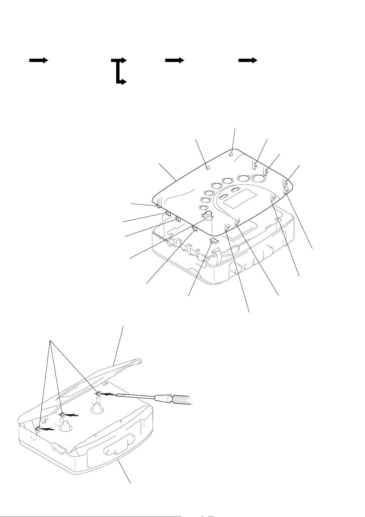
CABINET (FRONT) ASS’Y
1
Insert the precision screwdriver
(1.4 mm flat-blade) in to the slit
at claw A and release the claw.
2
Remove the cabinet (front) ass’y.
(Release all claw B to N in
alphabetical order.)
Note: On installation cabinet (front) ass’y
adjust the S306 and joint (MB).
M
Cabinet (front) ass’y
N
MECHANISM DECK
(MF-WMFX251-114)
(Page 8)
B
BELT,
MOTOR (REEL/CAPSTAN)
(M901)
(Page 8)
C
D
E
F
A
L
Joint (MB)
K
cassette holder
S306
G
H
I
J
cabinet (front) ass’y
– 6 –
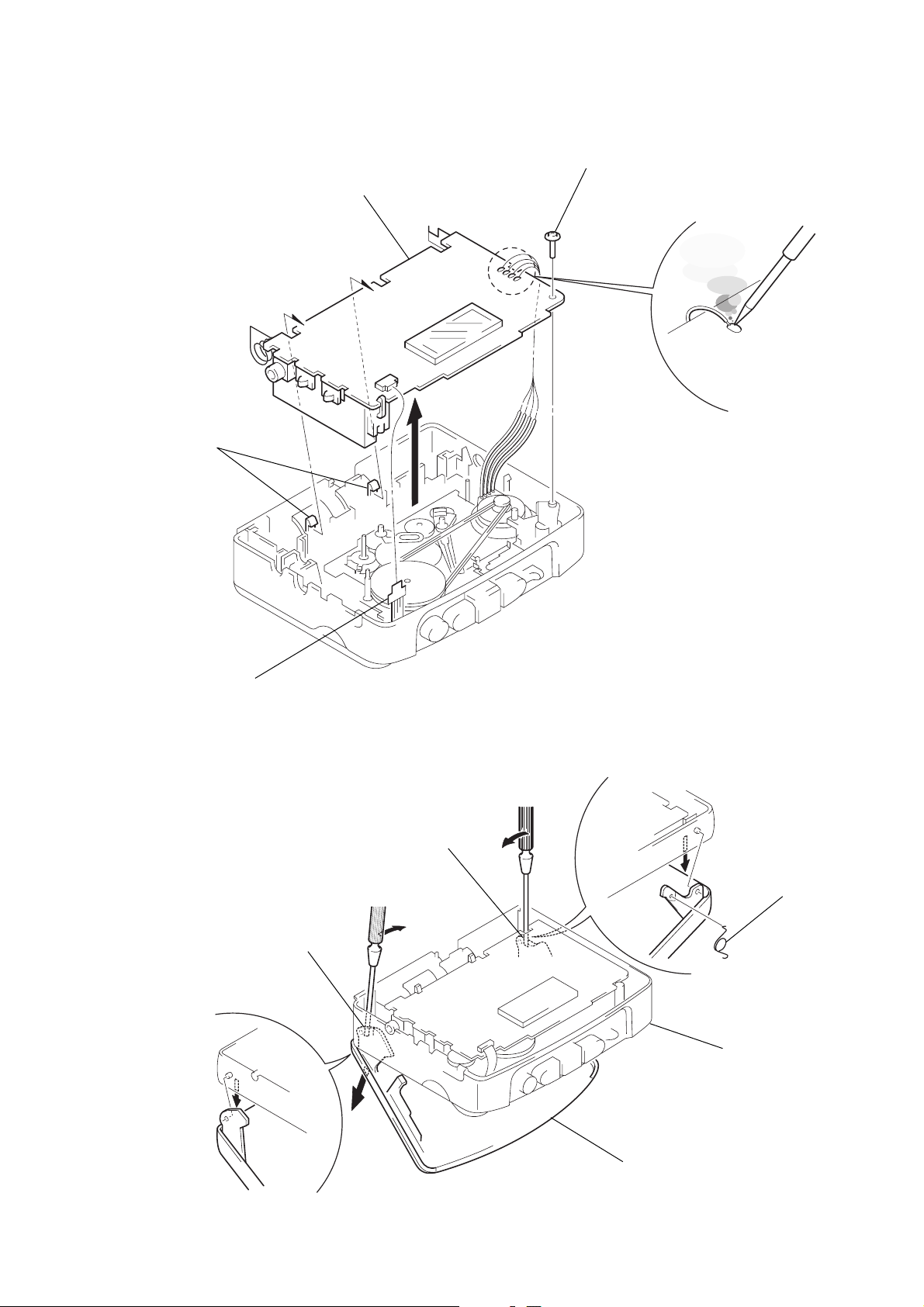
MAIN BOARD
g
4
two claws
5
MAIN board
3
screw (M1.4)
2
Removal the
four solders.
1
flexible board
(CN301)
CASSETTE HOLDER
2
Insert a precision screwdriver
(1.4 mm flat-blade) vertically
in to portion A to release the
hinge plate.
3
Portion B to release the
hinge plate.
A
B
5
torsion sprin
center cabinet
– 7 –
1
Open the cassette holder.
4
cassette holder
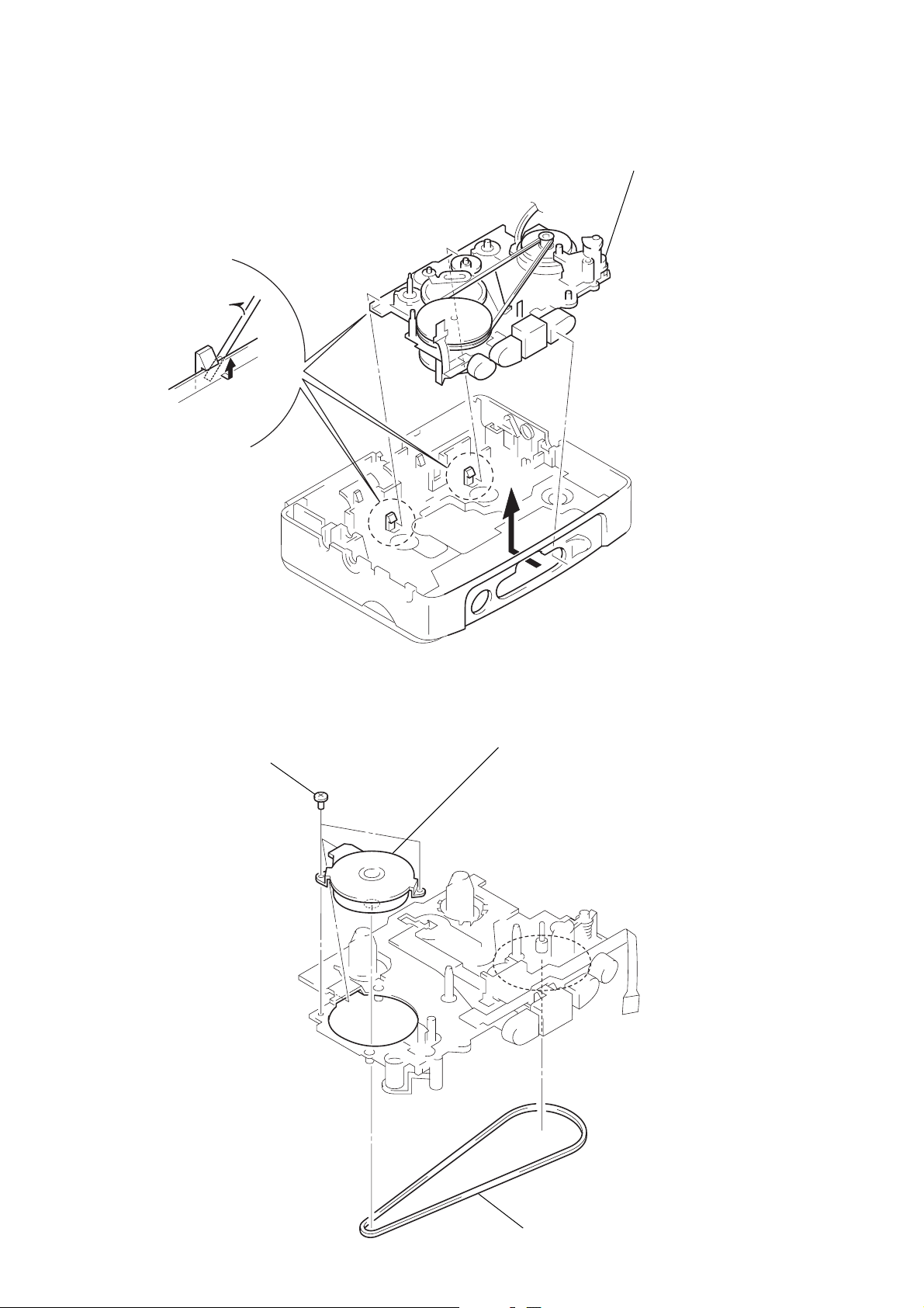
MECHANISM DECK (MF-WMFX251-114)
1
Insert the precision screwdriver
(1.4 mm flat-blade) in the slit
and relese two claws.
A
2
Remove the mechanism deck
(MF-WMFX251-114) in the
direction of the arrow A.
BELT, MOTOR (REEL/CAPSTAN) (M901)
2
two screws
×
1.6)
(M1.4
3
motor (reel/capstan)
(M901)
– 8 –
1
belt
 Loading...