

Sony WMFX-193, WMFX-195 Service manual
WM-FX193/FX195
SERVICE MANUAL
Ver. 1.3 2005.06
With SUPPLEMENT 1
(9-927-646-81)
With SUPPLEMENT 2
(9-927-646-82)
Photo : WM-FX195
SPECIFICATIONS
• Frequency range
FM: 87.5 - 108 MHz (Italy, Saudi Arabia)
87.6 - 107.9 MHz (Other countries)
AM: 526.5 - 1606.5 kHz (Italy, Saudi Arabia))
531 - 1602 kHz (Other countries)
•Power requirement
3 V DC batteries R6 (AA) x 2
• Dimensions
89.1 x 117.7 x 35.5 mm (w/h/d) incl. projecting parts and
controls
• Mass
Approx. 140 g/Approx. 220 g incl. batteries and a cassette
US Model
WM-FX193
Canadian Model
AEP Model
E Model
Chinese Model
WM-FX193/FX195
Model Name Using Similar Mechanism NEW
Tape Transport Mechanism Type MF-WMFX195-114
9-927-646-12
2005F02-1
© 2005.06
• Supplied accessories
Stereo headphones or Stereo earphones (1)/Belt clip (1)
Design and specifications are subject to change without notice.
Battery life (approximate hours) (EIAJ*)
Sony alkaline LR6 (SG) Sony R6P (SR)
playback 25 7.5
radio 55 18
* Measured value by the standard of EIAJ (Electronic
Industries Association of Japan). (Using a Sony HF series
cassette tape)
Note
• The battery life may shorten depending on the operation of
the unit.
RADIO CASSETTE PLAYER
Sony Corporation
Personal Audio Group
Published by Sony Engineering Corporation
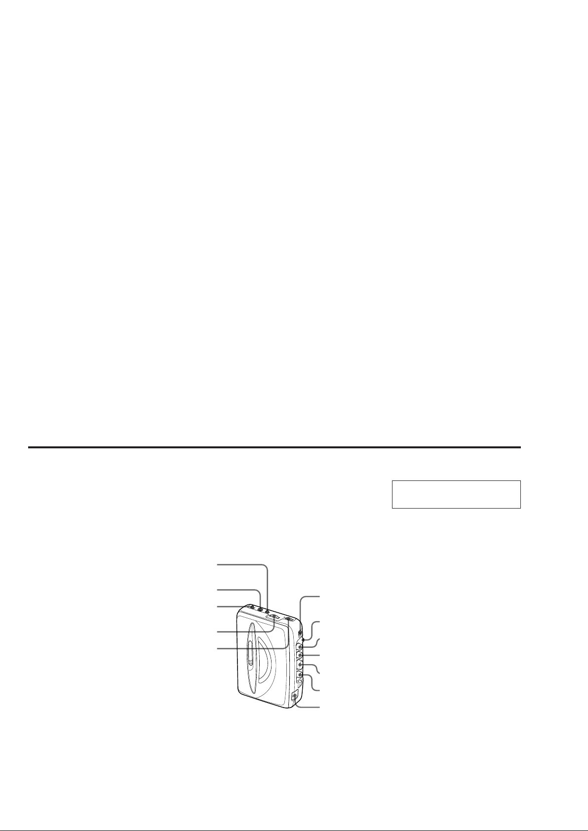
TABLE OF CONTENTS
Specifications ........................................................................... 1
1. GENERAL
Location and Function of Controls .................................... 2
2. DISASSEMBLY
2-1. Cabinet (Rear) Sub ASSY .......................................... 3
2-2. Main Board ................................................................. 3
2-3. Mechanism Deck ........................................................ 4
2-4. Belt, Capstan/Reel Motor (M901) .............................. 4
2-5. Holder Sub ASSY, Cassette ........................................ 5
3. ADJUSTMENTS
3-1. Mechanical Adjustments............................................. 6
3-2. Electrical Adjustments................................................ 6
4. DIAGRAMS
4-1. Block Diagram............................................................ 9
4-2. Printed Wiring Boards ...............................................11
4-3. Schematic Diagram................................................... 13
5. EXPLODED VIEWS
5-1. Cabinet Section......................................................... 17
5-2. Mechanism Section -1 .............................................. 19
5-3. Mechanism Section -2 .............................................. 20
6. ELECTRICAL PARTS LIST ................................... 21
Flexible Circuit Board Repairing
• Keep the temperature of the soldering iron around 270°C during
repairing.
• Do not touch the soldering iron on the same conductor of the
circuit board (within 3 times).
• Be careful not to apply force on the conductor when soldering or
unsoldering.
Notes on chip component replacement
• Never reuse a disconnected chip component.
• Notice that the minus side of a tantalum capacitor may be damaged by heat.
LOCATION AND FUNCTION OF CONTROLS
FM MODE
i
AVLS NORM/
LIMIT
TUNING
VOLUME
SECTION 1
GENERAL
FM/AM/TAPE
(RADIO OFF)
BATT
x
m
nPLAY
M
MEGA BASS/
OFF (FX195 only)
This section is extracted from
instruction manual.
– 2 –

SECTION 2
DISASSEMBLY
z
The equipment can be removed using the following procedure.
Set
Main boardCabinet (rear) sub ASSY
Holder sub ASSY, Cassette
Note : Follow the disassembly procedure in the numerical order given.
2-1. CABINET (REAR) SUB ASSY
Mechanism deck Belt, Capstan/reel moter (M901)
5
Claw
3
Claws
Claws
4
5
Claw
4
2
6
Claws
4
Holder sub ASSY, Cassette
5
Claw
3
Claws
Claw
3
Claws
Cabinet (front)
Cabinet (rear) sub ASSY
1
Screws B1.7x9
2-2. MAIN BOARD
3
Claws
Main board
White
Red
Orange
4
Black
2
Remove solder
1
Head flexible board
Screw WH1.4
– 3 –
Cabinet (front)
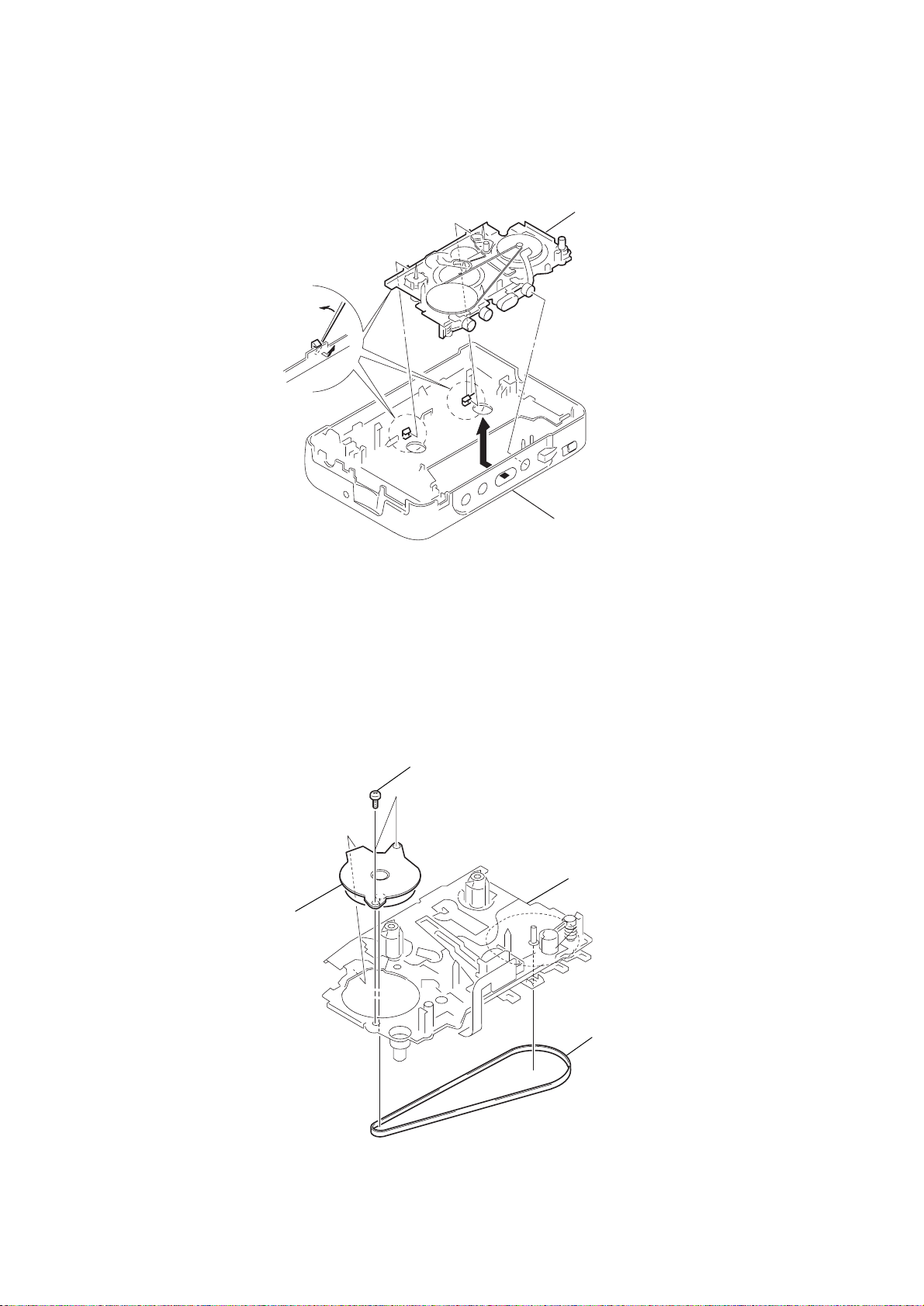
2-3. MECHANISM DECK
k
k
1
Insert the precision screwdriver
(1.4 mm flat-blabe) in to the slit
and release two claws.
Mechanism dec
2
Cabinet (front)
2-4. BELT, CAPSTAN/REEL MOTOR (M901)
3
Capstan/reel motor (M901)
2
Screws (M1.4)
Mechanism dec
1
Belt
– 4 –
e
Holder sub ASSY, Cassette
Cabinet (front)
5
4
1
3
2
Spring (torsion)
Hinge
Hinge
Dial indicator
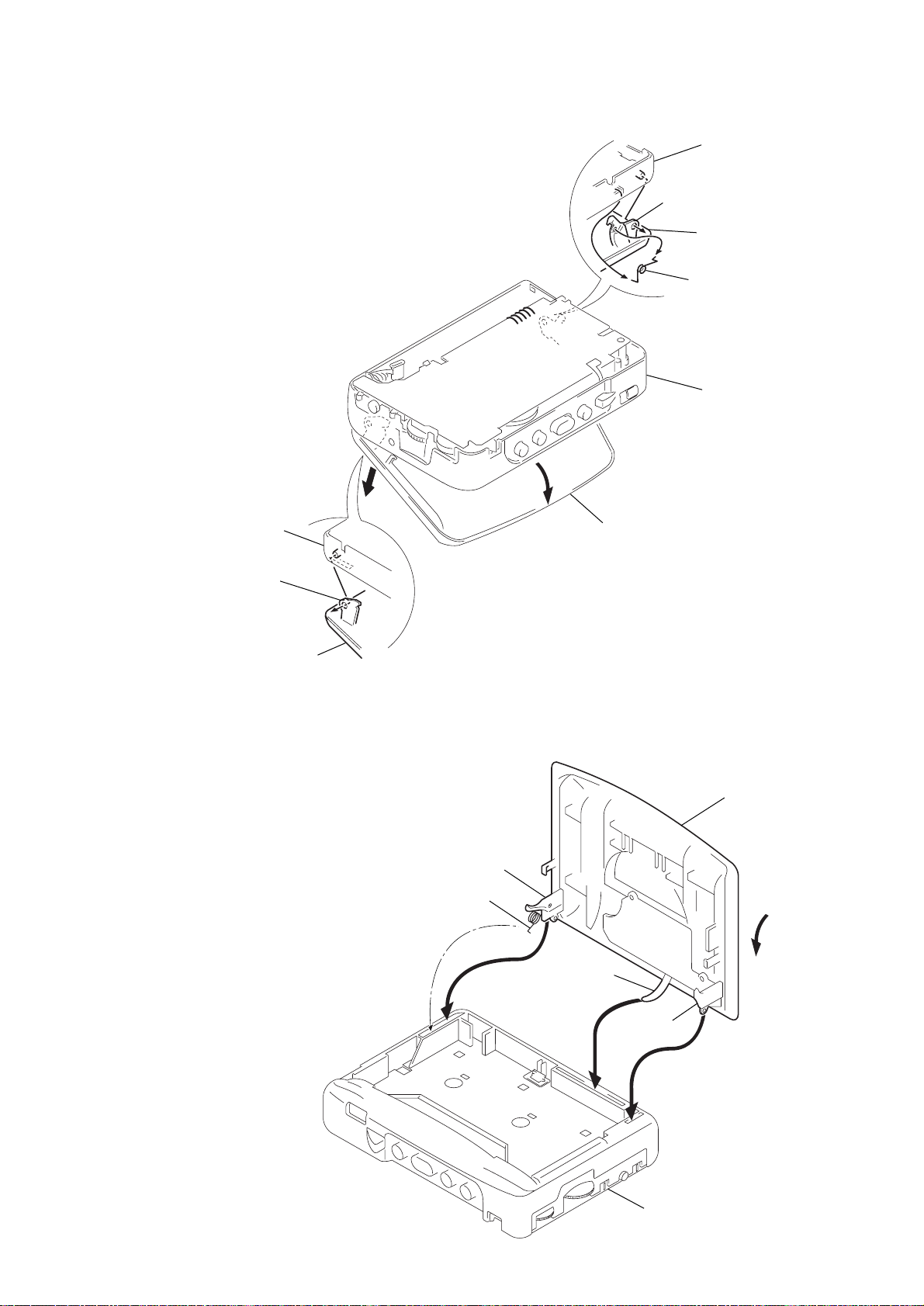
2-5. HOLDER SUB ASSY, CASSETTE
Cabinet (front)
3
Move it away from projection
Holder sub ASSY, Cassett
4
Spring (torsion)
Cabinet (front)
5
Cabinet (front)
2
Move it away
from projection
Holder sub ASSY, Cassette
z
CAUTIONS DURING ASSEMBLY
1 Insert the dial indicator to the square hole of the cabinet
(front) and align to the pointer.
2 Insert the spring (torsion) in to the L shape slot as shown in
the figure.
3, 4 Insert the hinge of the “Holder sub ASSY, Cassette”.
5 Close the “Holder sub ASSY, Cassette” then press in.
1
Holder sub ASSY, Cassette
– 5 –
SECTION 3
r
t
ADJUSTMENTS
3-1. MECHANICAL ADJUSTMENTS
PRECAUTION
1. Clean the following parts with a denatured-alcohol-moistened
swab :
playback head pinch roller
capstan rubber belt
2. Demagnetize the playback head with a head demagnetizer.
3. Do not use a magnetized screwdriver for the adjustments.
4. These measurement and adjustment should be performed with
the rated power supply voltage (2.5 V) unless otherwise noted.
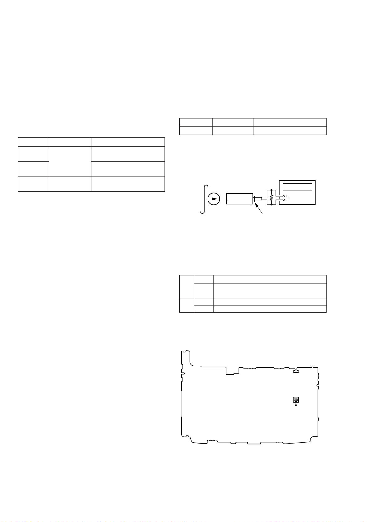
Torque Measurement
Mode Torque Meter Meter Reading
FWD
FWD 0.4 – 2 g • cm
back tension (0.006 – 0.027 oz• inch)
FF, REW CQ-201B
CQ-102C
20 – 30 g • cm
(0.28 – 0.41 oz• inch)
more than 40 g • cm
(more than 0.56 oz• inch)
3-2. ELECTRICAL ADJUSTMENTS
PRECAUTION
• Supplied voltage : 2.5V.
• Switch and control position
MEGA BASS switch : OFF (FX195)
VOLUME control : maximum
AVLS switch : NORM
Test T ape
Type Signal Used for
WS-48A 3kHz, 0dB Tape Speed Adjustment
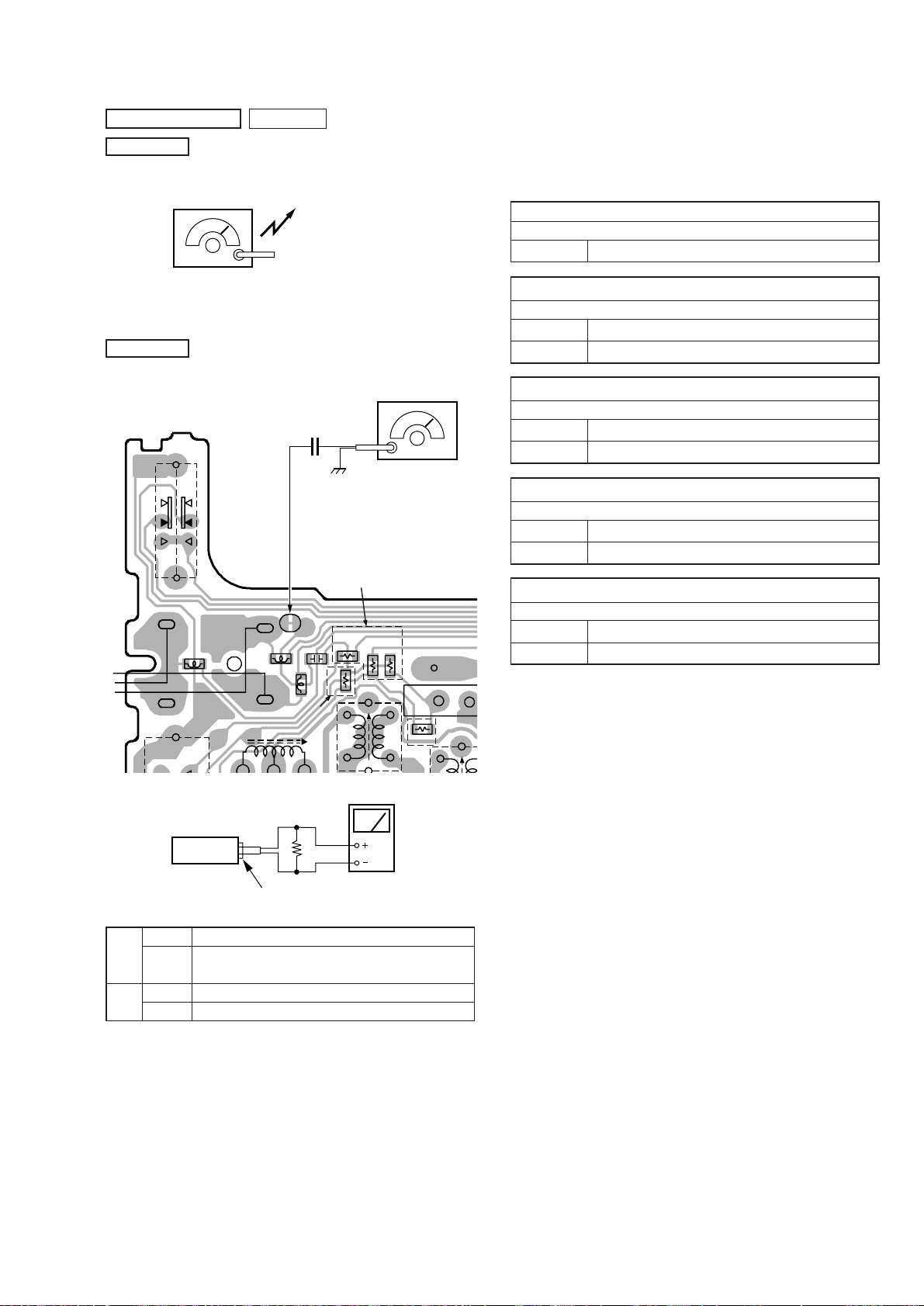
Tape Speed Adjustment
Procedure :
test tape
WS-48A
(3kHz, 0dB)
set
frequency counte
*
1
phones jack (J302)
1. Playback WS-48A (tape center part) and adjust RV601 so that
the frequency counter reading becomes 3,000Hz.
Standard value : 2,985–3,015Hz
2. Playback WS-48A (tape top and end).
Check that frequency counter reading is within 1.5% of the reading of step 1.
*1
FX193 E, Chines, Saudi Arabia,
16Ω
FX195
FX193 US, Canadian, AEP, French, Italian, CEV
32Ω
FX195 Canadian
E, Chines, Saudi Arabia, AEP, French, Italian,
CEV
• Abbreviation
CEV : Ukraine, Hungary, Czech
Adjustment Location :
[MAIN BOARD] (Conductor side)
RV601 : Tape Speed Adjustmen
– 6 –
TUNER SECTION
r
1
T
N
AM Section
BAND : AM
AM RF signal
generator
0 dB = 1µV
Put the lead-wire
antenna close to
the set.
• Repeat the procedures in each adjustment several times, and the
frequency coverage and tracking adjustments should be finally
done by the trimmer capacitors.
< > : US, Canadian, E5, E6 model
[ ] : Italian, Saudi Arabia model
AM IF ADJUSTMENT
Adjust for a maximum reading on level meter.
T1 455kHz
30% amplitude modulation by 400Hz
signal.
Output level : as low as possible
FM Section
BAND : FM
[MAIN BOARD]
(Conductor side)
-1
S1
0.01
TP1
-2
TP1
TP339
FB101
TP338
US, CND, E5, E6 MODEL
TP9
FB301
TP8
C12
FB201
FM RF signal
generator
µ
F
22.5kHz frequency deviation
by 400Hz signal.
Output level :
as low as possible
EXCEPT US, CND,
E5, E6 MODEL
JR2
JR5
L4
JR3
JR1
BAT
CP
US, C
JR4
AM FREQUENCY COVERAGE ADJUSTMENT
Adjust for a maximum reading on level meter.
L4 505kHz [516.5kHz]
CT4 1,690kHz < 1,770kHz> [1,631.5kHz]
AM TRACKING ADJUSTMENT
Adjust for a maximum reading on level meter.
L1 620kHz
CT1 1,400kHz
FM FREQUENCY COVERAGE ADJUSTMENT
Adjust for a maximum reading on level meter.
L3 86MHz [87.35MHz]
CT3 109.5MHz [108.25MHz]
FM TRACKING ADJUSTMENT
Adjust for a maximum reading on level meter.
L2 86MHz [87.35MHz]
CT2 109.5MHz [108.25MHz]
Adjustment Location : Main board (See page 8)
T1
*
1
set
phones jack (J302)
*1
FX193 E, Chines, Saudi Arabia,
16Ω
FX195
FX193 US, Canadian, AEP, French, Italian, CEV
32Ω
FX195 Canadian
E, Chines, Saudi Arabia, AEP, French, Italian,
CEV
• Abbreviation
CND : Canadian
E5, E6 :South America
CEV : Ukraine, Hungary, Czech
level mete
– 7 –
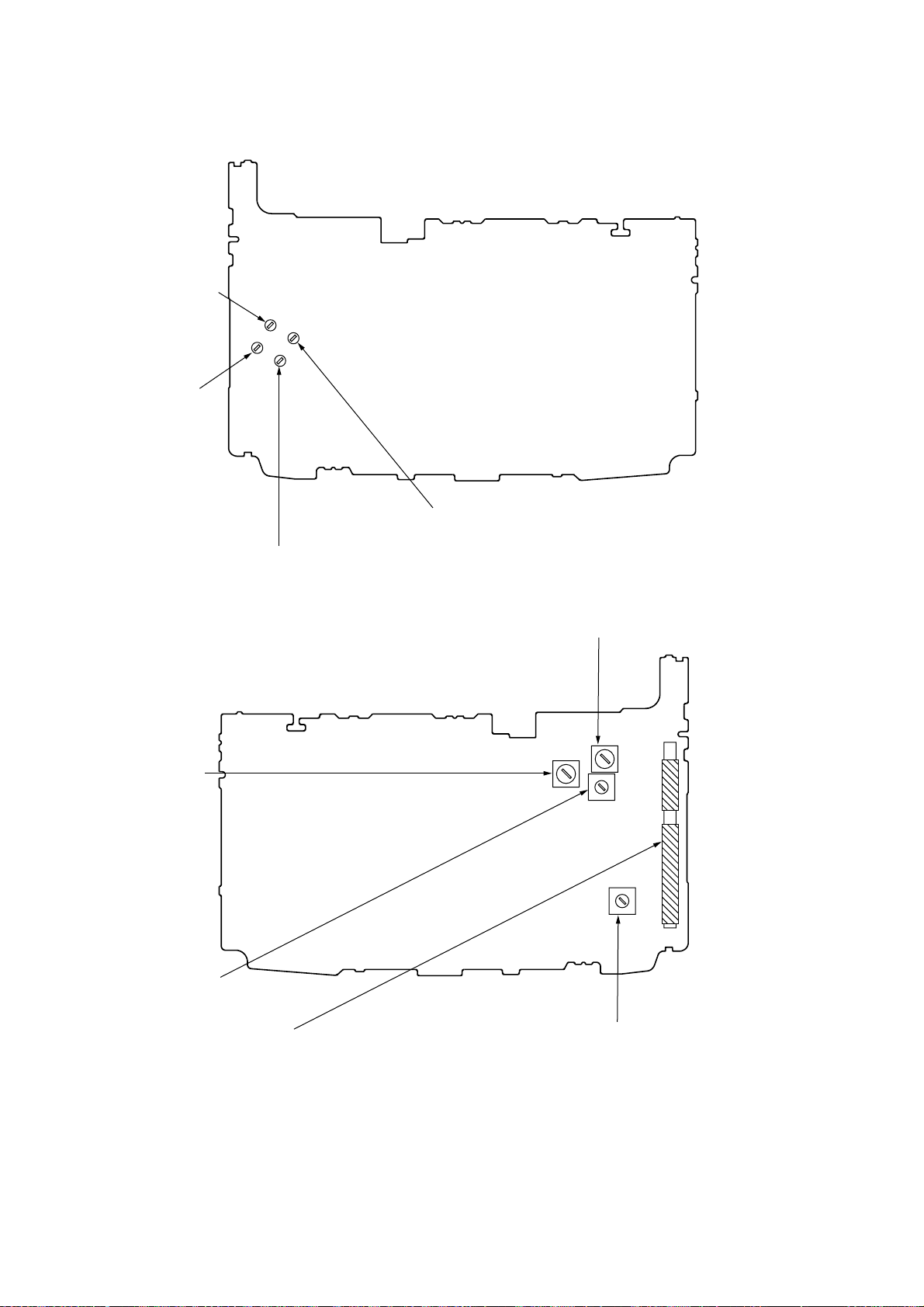
Adjustment Location :
CT1 : AM Tracking Adjustment
CT4 : AM Frequency
Coverage Adjustment
[MAIN BOARD] (Conductor side)
CT2 : FM Tracking Adjustment
CT3 : FM Frequency Coverage Adjustment
T1 : AM IF Adjustment
L2 : FM Tracking Adjustment
L1 : AM Tracking Adjustment
L4 : AM Frequency Coverage Adjustment
[MAIN BOARD] (Component side)
L3: FM Frequency Coverage Adjustment
– 8 –
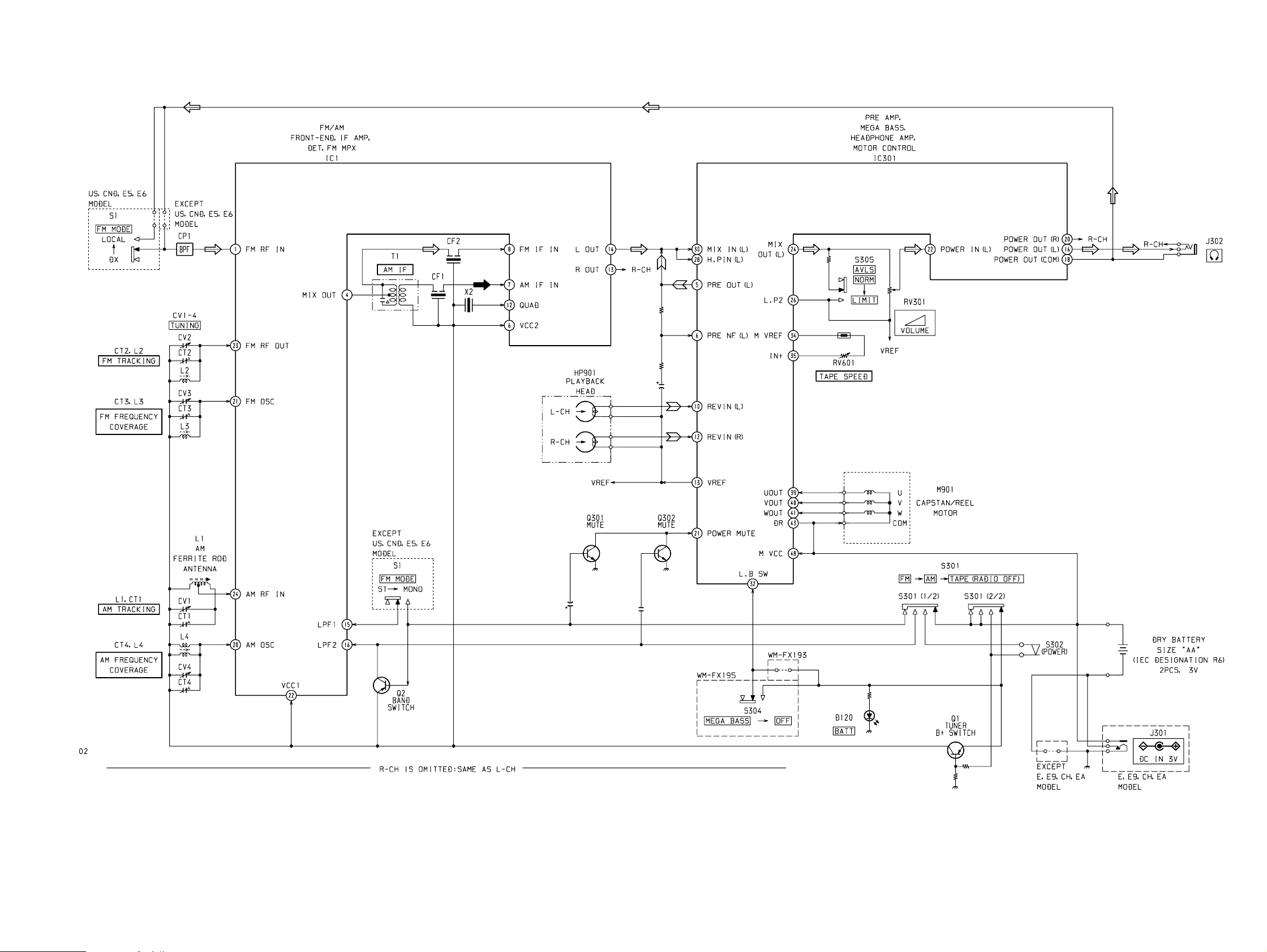
4-1. BLOCK DIAGRAM
WM-FX193/FX195
SECTION 4
DIAGRAMS
• Abbreviation
CND : Canadian
EA : Saudi Arabia
CH : Chinese
E : Indication of country of origin
E9 : No Indication of country of origin
CEV :Ukrine, Hungary, Czech
E5, E6 : South America
FR : French
– 9 – – 10 –
• Signal path.
F : FM
f : AM
E : PB
 Loading...