

Sony WMFX-161 Service manual
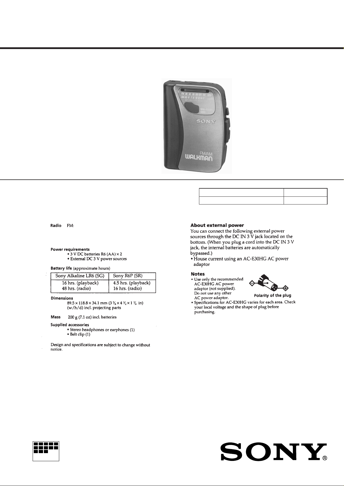
WM-FX161
SERVICE MANUAL
SPECIFICATIONS
87.6 – 108 MHz (Canadian)
87.6 – 107.9 MHz (E)
AM: 530 – 1,710 kHz (Canadian)
531 – 1,602 kHz (E)
Canadian Model
E Model
Model Name Using Similar Mechanism WM-FX101
Tape Transport Mechanism Type MF-WMFX103Y-48
MICROFILM
RADIO CASSETTE PLAYER
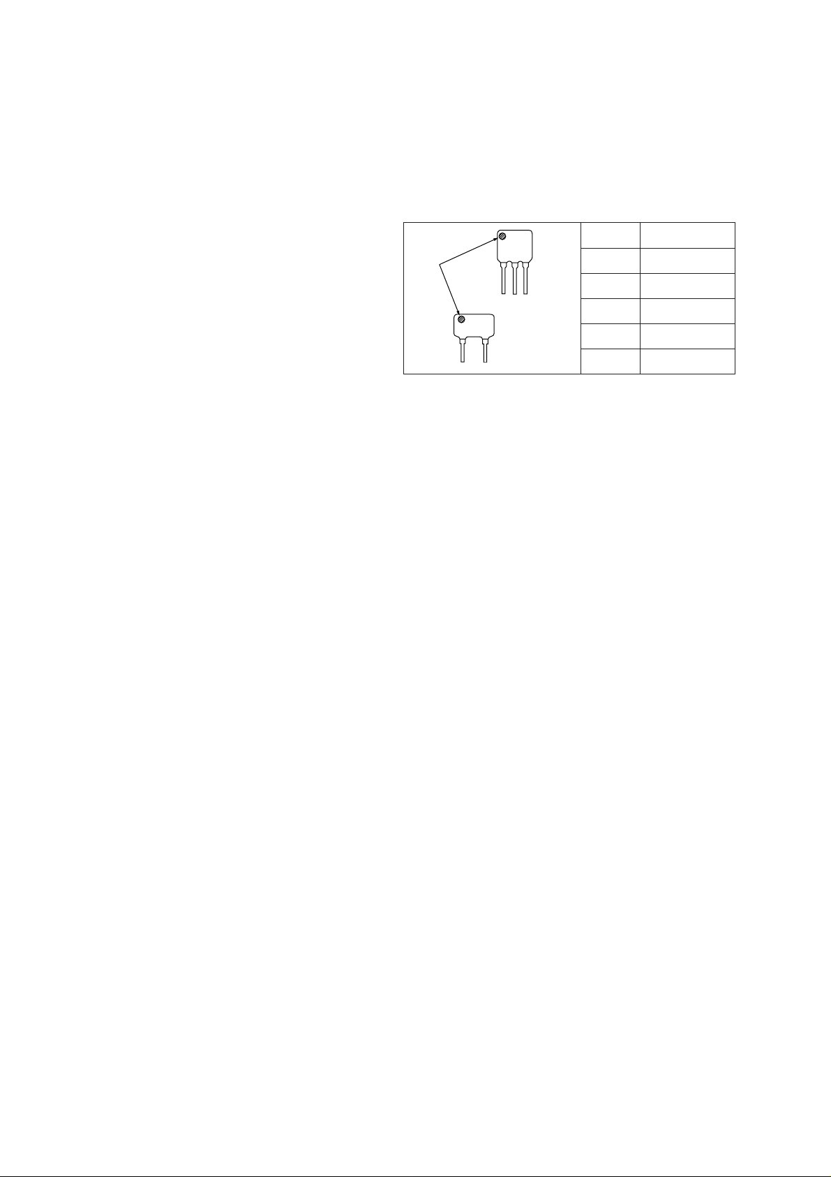
TABLE OF CONTENTS
SERVICING NOTES
1. GENERAL ................................................................... 3
2. DISASSEMBLY ......................................................... 4
3. DIAL POINTER SETTING .................................. 6
4. MECHANICAL ADJUSTMENTS....................... 7
5. ELECTRICAL ADJUSTMENTS......................... 7
6. DIAGRAMS
6-1. Block Diagram ................................................................ 9
6-2. Printed Wiring Board ...................................................... 11
6-3. Schematic Diagram ......................................................... 13
7. EXPLODED VIEWS ................................................ 16
8. ELECTRICAL PARTS LIST ............................... 18
HOW TO CHANGE THE CERAMIC FILTERS
This model is used two ceramic filters of CF2 and X2.
You must used same type of color marked ceramic filters in order
to meet same specifications.
Therefore, the ceramic filter must changed two pieces together
since it's supply two pieces in one package as a spare parts.
CF2
mark
X2
Flexible Circuit Board Repairing
• Keep the temperature of the soldering iron around 270 ˚C during repairing.
• Do not touch the soldering iron on the same conductor of the
circuit board (within 3 times).
• Be careful not to apply force on the conductor when soldering
or unsoldering.
Notes on chip component replacement
• Never reuse a disconnected chip component.
• Notice that the minus side of a tantalum capacitor may be damaged by heat.
Mark Center frequency
red 10.70MHz
blue 10.67MHz
orange 10.73MHz
black 10.64MHz
white 10.76MHz
– 2 –
SECTION 1
GENERAL
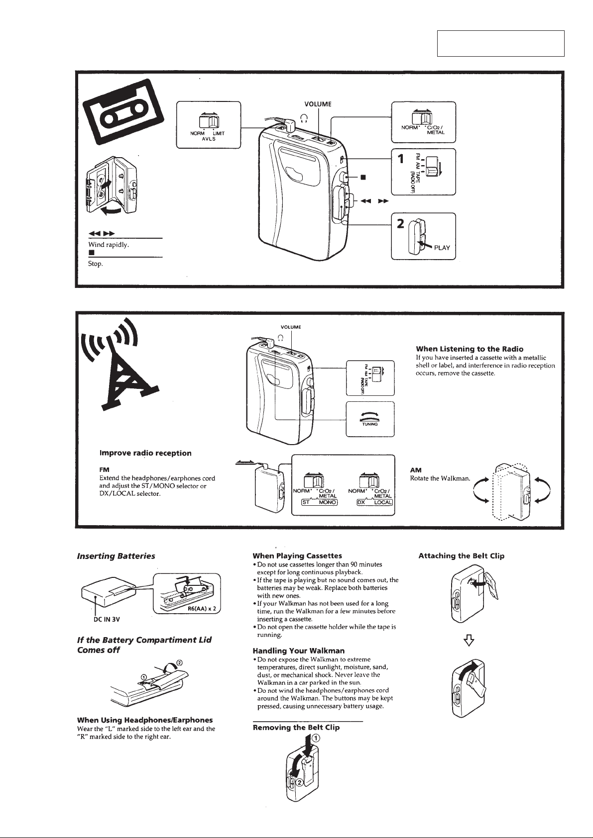
This section is extracted from
instruction manual.
– 3 –
• This set can be disassembled in the order shown below.
e
R
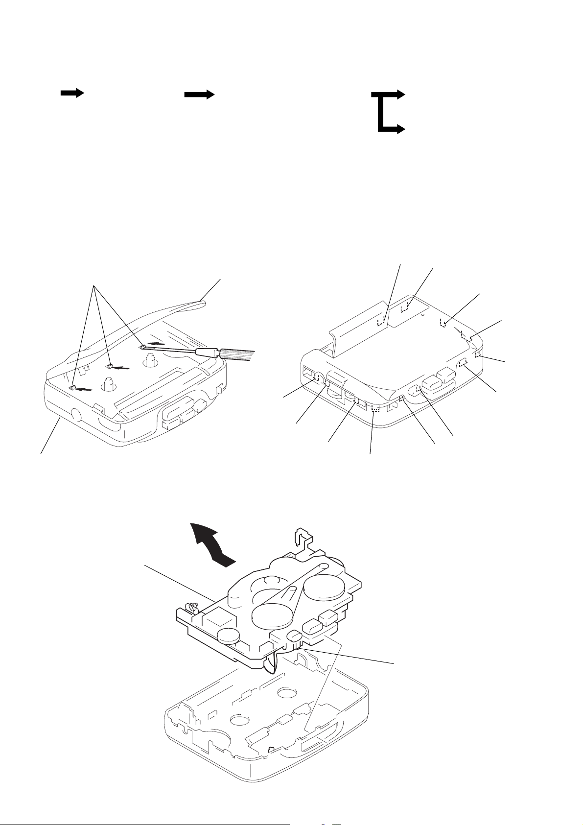
SECTION 2
DISASSEMBLY
SET
Note: Follow the disassembly procedure in the numerical order given.
CABINET (REAR) ASS’Y
MECHANISM DECK (MF-WMFX103Y-48)
AND MAIN BOARD
CABINET (REAR) ASS’Y
1
Insert the precision screw driver
(1.4 mm flat-blade) in to the slit
at claw A and release the claw.
2
Remove the cabinet (rear) ass’y. (Release all claw B to M in alphabetical
order.)
A
cassette holder
MAIN BOARD
CASSETTE HOLDE
B
C
D
E
I
cabinet (rear) ass’y
MECHANISM DECK (MF-WMFX103Y-48)
AND MAIN BOARD
1
Remove the mechanism deck
(MF-WMFX103Y-48) and MAIN board
in the direction of the arrow.
F
G
H
K
M
L
J
Note: Make sure to put the head
flexible board to ditch befor
install the mechanism deck
and MAIN board.
– 4 –
 Loading...