

Sony WM-FX141 Service Manual
WM-FX141
SERVICE MANUAL
Ver 1.3 1999. 05
With SUPPLEMENT-1 (9-923-296-81)
With SUPPLEMENT-2 (9-923-296-82)
US Model
AEP Model
E Model
Model Name Using Similar Mechanism WM-FX101
Tape Transport Mechanism Type MF-WMFX103-48
SPECIFICATIONS
Radio Frequency
FM : 87.6 – 108 MHz (US, Chilean, Latin America, Central and
South America Models)
: 65.0 – 107.9MHz (East European Model)
: 87.6 – 107.9 MHz (Other Models)
AM : 530 – 1,710 kHz (US, Chilean, Latin America, Central and
South America Models)
: 531 – 1,602kHz (Other Models)
Power requirements
3V DC batteries R6 (size AA) × 2
External DC 3V power sources
Battery life
(Aprroximate hours)
Battery Playback Radio
Sony alkaline LR6 (SG) 16 hrs 48 hrs
Sony R6P (SR) 4.5 hrs 16 hrs
Dimensions
93.9 × 118.5 × 35.9 mm (w/h/d)
(33/4 × 43/4 × 13/16 in.) incl. projecting parts
Mass
205g (7.3 oz) incl.batteries
Supplied accessories
• Stereo headphones or earphones (1)
• Belt clip (1)
Design and specifications are subject to change without notice.
MICROFILM
RADIO CASSETTE PLAYER

TABLE OF CONTENTS
1. GENERAL ·········································································· 3
2. DISASSEMBLY
2-1. Cabinet (Rear) ································································· 4
2-2. Mechanism Deck and Main Board ································· 4
2-3. Main Board ····································································· 5
2-4. Cassette Lid····································································· 5
2-5. Dial Pointer Setting························································· 5
3. ADJUSTMENT
3-1. Mechanical Adjustment ·················································· 6
3-2. Electrical Adjustment······················································6
4. DIAGRAMS
4-1. Block Diagram ································································ 9
4-2. Schematic Diagram ······················································· 11
4-3. Printed Wiring Board ···················································· 13
4-4. IC Block Diagram ························································· 17
5. EXPLODED VIEWS
5-1. Cabinet and Board Section ··········································· 18
5-2. Mechanism Section (MF-WMFX103-48) ···················· 19
6. ELECTRICAL PARTS LIST ······································· 20
Notes on chip component replacement
• Never reuse a disconnected chip component.
• Notice that the minus side of a tantalum capacitor may be
damaged by heat.
Flexible Circuit Board Repairing
• Keep the temperature of soldering iron around 270˚C
during repairing.
• Do not touch the soldering iron on the same conductor of the
circuit board (within 3 times).
• Be careful not to apply force on the conductor when soldering
or unsoldering.
— 2 —
SECTION 1
GENERAL
This section is extracted
from instruction manual.
— 3 —
DISASSEMBLY
k
Note : Disassemble the unit in the order as shown below.
SECTION 2
Cabinet (Rear) Mechanism deck and main board
Main board
Cassette lid
Dial pointer setting
Note : Follow the disassembly procedure in the numerical order given.
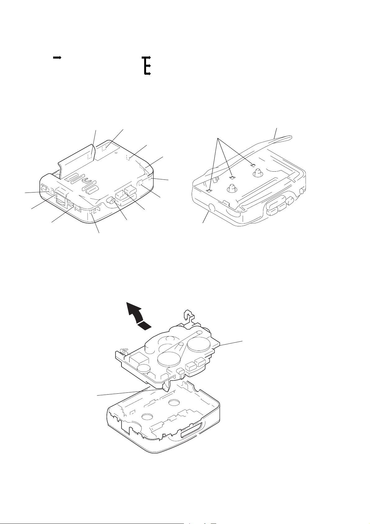
2-1. CABINET (REAR)
B
F
G
H
J
C
D
E
I
K
M
L
Cabinet(rear)
Cassette lid
A
1
Open the cassette lid and release claw A.
2
Remove the cabinet(rear).(Release
all claws
B
from M in alphabetical order.)
2-2. MECHANISM DECK AND MAIN BOARD
1
Remove the mechanism deck
and main board in the
direction of the arrow.
head flexible board
mechanism dec
and MAIN board
*
note for installation :
Make sure to put the head flexible
board to ditch before install the
mechanism deck and MAIN board.
— 4 —
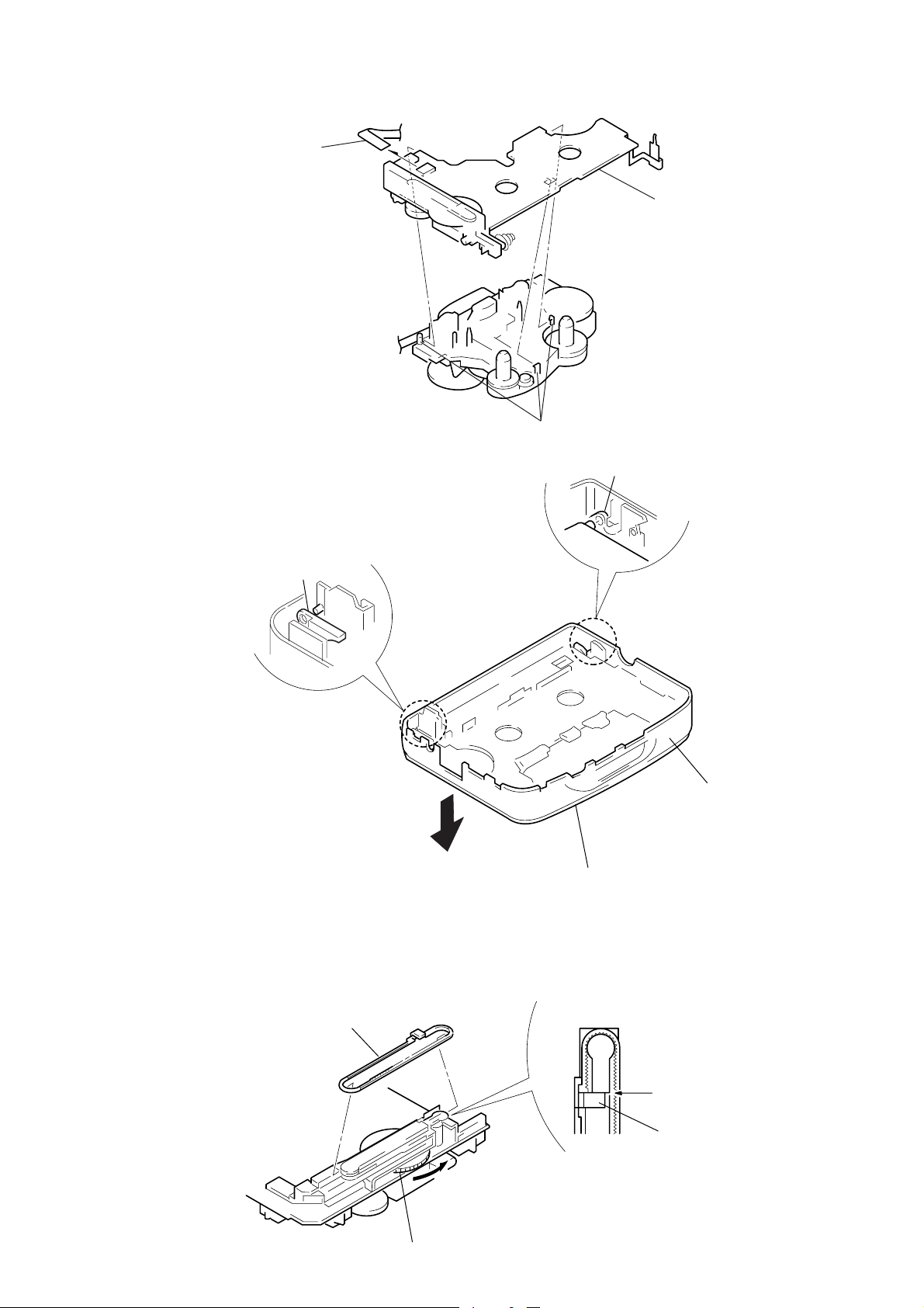
2-3. MAIN BOARD
d
t
r
1
head flexible board
2
claws
3
MAIN boar
2-4. CASSETTE LID
A
1
Release the catch A.
B
2
Release the catch B.
3
Cassette lid
(Remove it in the
direction of the arrow)
Front cabine
2-5. DIAL POINTER SETTING
Pointer
B
2
Align pointer with arrow
marked side as shown in Fig.1
and then fit to groove in the
order of
A
1
Rotate tune knob fully to arrow direction.
A
and B.
Fig. 1
— 5 —
Align
Pointe

SECTION 3
ADJUSTMENTS
3-1. MECHANICAL ADJUSTMENTS
Precaution
1. Clean the following parts with a denatured-alcohol-moistend
swab :
playback head pinch roller
capstan rubber belts
2. Demagnetize the playback head with a head demagnetizer.
3. Do not use a magnetized screwdriver for the adjustments.
4. After the adjustments, apply suitable locking compound to the
parts adjusted.
5. The adjustments should be perfomed with the rated power supply
voltage (2.5V) unless otherwise noted.
Torque Measurement
Mode Torque meter Meter reading
FWD
FWD
Back T ension
FF, REW
CQ-102C
CQ-201B
20 to 42 g•cm
(0.28 to 0.58 oz•inch)
less than 2 g•cm
(less than 0.03 oz•inch)
more than 60 g•cm
(more than 0.83 oz•inch)
3-2. ELECTRICAL ADJUSTMENTS
Precaution
• Supplied voltage : 2.5V
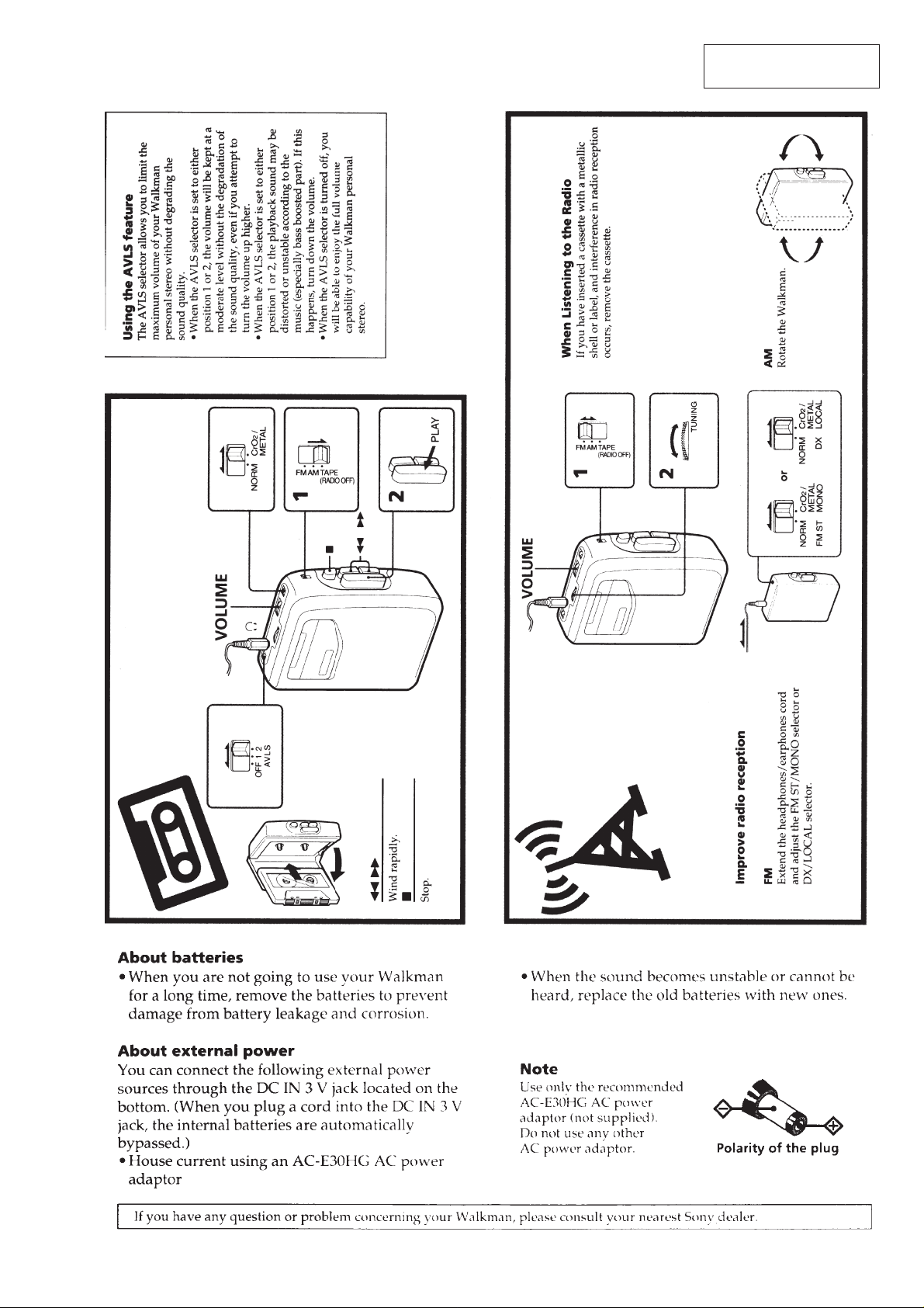
• Switch and control position
TAPE switch : NORM
VOLUME control : maximum
AVLS switch : OFF
TAPE SECTION
• FUNCTION switch : TAPE
Test tape
Type Signal Used for
WS-48A 3kHz, 0dB Tape Speed Adjustment
Tape speed adjustment
Tape selection adjustment : NORM
Procedure :
test tape
WS-48A
(3kHz, 0dB)
16
Ω
0dB=0.775V
frequency
counter
set
J302(phones)
Adjustment V alue: normal tape speed
Adjust the tape speed adjustment R V601, so that the freqency counter
reading becomes 3,000Hz.
Specification Value:
Digital frequency counter
2,945 to 3,015Hz
Frequency difference between the beginning and the end of the tape
should be within 1.5% (45Hz).
Adjustment Location :
— 6 —
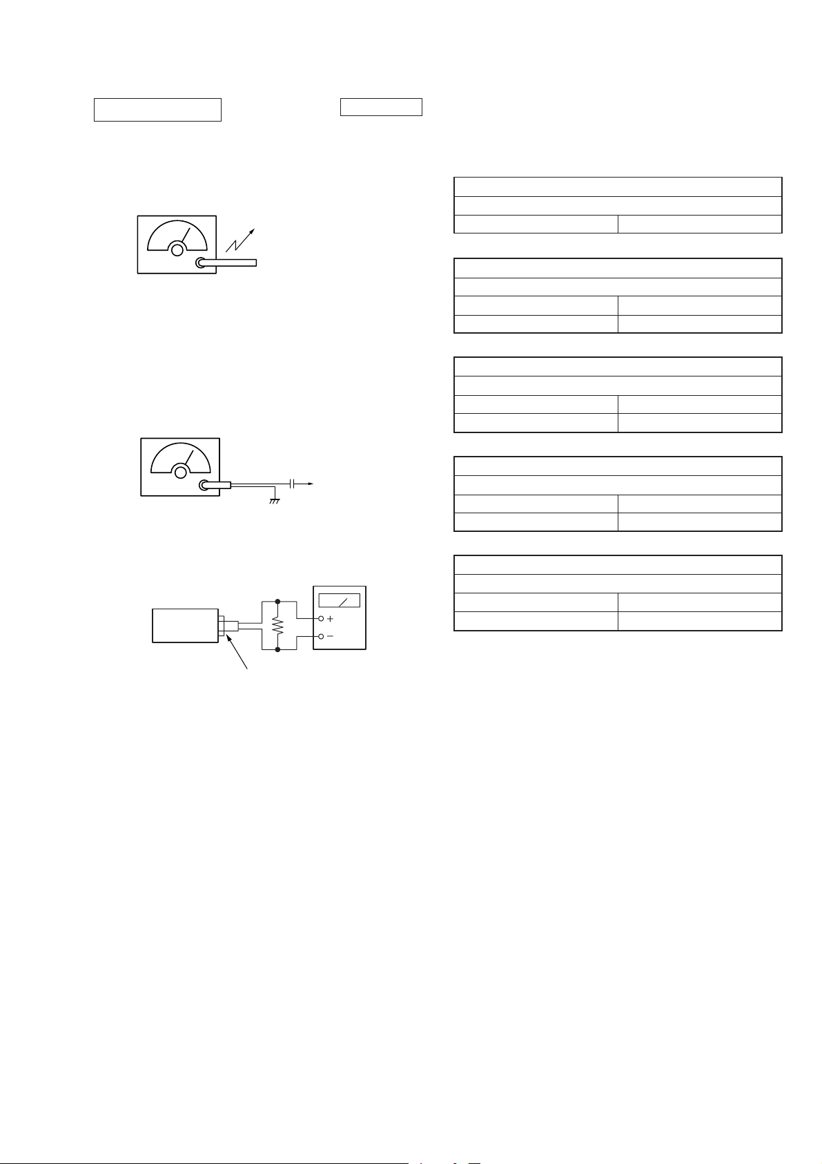
TUNER SECTION
l
r
[AM]
BAND: AM
Signal generator
AM RF signal
generator
30% amplitude modulation by 400Hz
signal.
Output level : as low as possible
Put the lead-wire
antenna close to
the set.
0 dB = 1 µV
• Repeat the procedures in each adjustment several times for the
maximum level meter indication.
• The frequency coverage and tracking adjustments should be
finally done by the trimmer capacitors.
AM IF ADJUSTMENT
Adjust for a maximum reading on level meter.
T1 455kHz
AM TRACKING ADJUSTMENT
Adjust for a maximum reading on level meter.
L1 620kHz(800kHz)
CT1 1,400kHz(1,300kHz)
[FM]
BAND : FM
Signal generator
FM RF signal
generator
75kHz(100%) amplitude modulation
by 1kHz signal.
Output level: as low as possible
set
0.01µF
16
J302 (phones)
antenna termina
level mete
Ω
AM FREQUENCY COVERAGE ADJUSTMENT
Adjust for a maximum reading on level meter.
L4 505kHz(516.5kHz)
CT4 1,750kHz(1,631.5kHz)
FM TRACKING ADJUSTMENT
Adjust for a maximum reading on level meter.
L2 86.0MHz[64MHz]
CT2 109.5MHz
FM FREQUENCY COVERAGE ADJUSTMENT
Adjust for a maximum reading on level meter.
L3 86.0MHz[64MHz]
CT3 109.5MHz
( ) :E, Mexican, East European, AEP
[ ] : East European
Adjustment Location: Main board (See page 8)
— 7 —
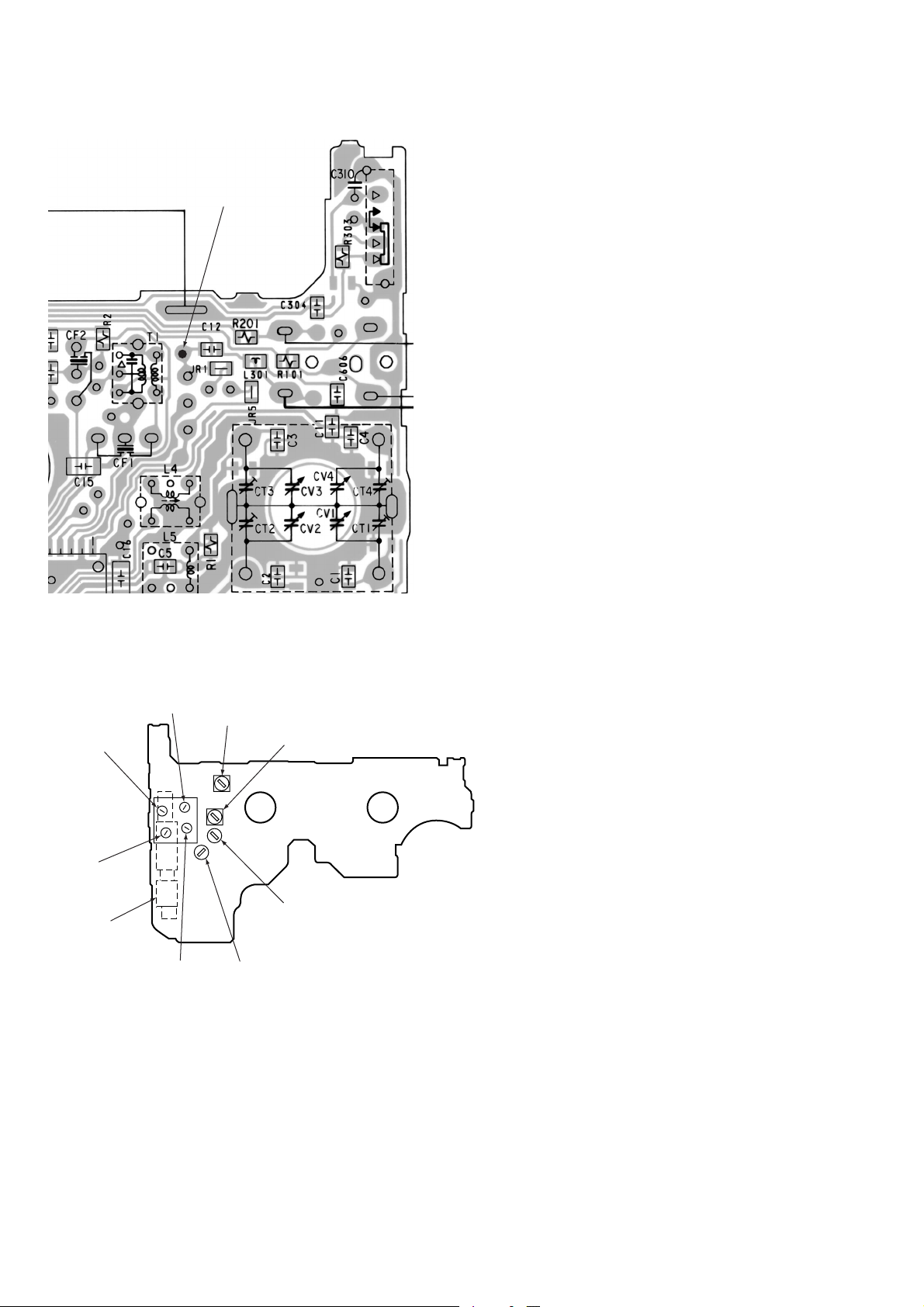
Adjustment Location : Main board
antenna terminal
CT4
AM Frequency
coverage
Adjustment
CT1
AM T rac king
Adjustment
L1
AM T rac king
Adjustment
CT3
FM Frequency
coverage
Adjustment
CT2
FM T rac king
Adjustment
T1
AM IF
Adjustment
L2
FM T rac king
Adjustment
L4
AM Frequency
coverage Adjustment
L3
FM Frequency
coverage
Adjustment
— 8 —
 Loading...