

Sony WMFX-121-V Service manual
WM-FX121V
MICROFILM
SERVICE MANUAL
Model Name Using Similar Mechanism WM-FX101
T ape T r ansport Mechanism T ype MF-WMFX103Y-48
SPECIFICATIONS
E Model
Radio Frequency
FM : 87.6 – 107.9 MHz
AM : 531 – 1,602 kHz
Power Requirements
3V DC Batteries AA (R6) x 2
External DC 3 V power sources
Battery Life
(approximate hours when using the batteries specified below)
Battery Playback Radio
Sony Alkaline LR6 (SG) 13 hours 30 hours
Sony R6P (SR) 4 hours 15 hours
Dimensions
118.8 x 89.5 x 34.1 mm (4 3/4 x 3 5/8 x 1 3/8 in.)
(w/h/d) incl. projecting parts
Mass
200g (7.1 oz) incl. batteries
Supplied Accessories
• Stereo headphones (1)
• Belt clip (1)
Design and specifications are subject to change without notice.
Using External Power Sources
Y ou can connect the follo wing external po wer sources through the DC IN 3V
jack located on the bottom.
(When you plug a cord into the DC IN 3 V jack, the internal batteries are
automatically bypassed.)
• House current using an AC-E30HG AC power adaptor
• 12 V car battery using a DCC-E130L car battery cord
Note:
Use only the recommended AC-E30HG AC
power adaptor (not supplied). Do not use any
other AC power adaptor.
Polarity of the plug
RADIO CASSETTE PLAYER
– 1 –
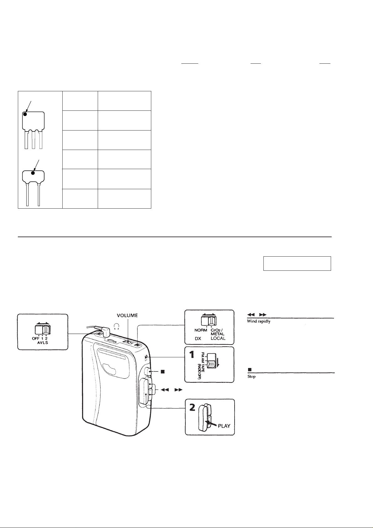
HOW TO CHANGED THE CERAMIC FILTERS
2
This model is used two ceramic filters of CF2, X2. You must used
same type of color marked ceramic filters in order to meet same
specifications.
Therefore, the ceramic filter must changed two pieces together since
it’s supply two pieces in one package as a spare parts.
color mark
color mark
red
CF
Center Frequency
10.70MHz
TABLE OF CONTEMTS
Section Title Page
SECTION 1 GENERAL ...................................................... 2
SECTION 2 DISASSEMBLY
2-1. Cabinet (Rear) Assembly...................................................... 3
2-2. Mechanism Deck and Main Board ....................................... 4
2-3. Main Board ........................................................................... 4
2-4. Cassette Lid........................................................................... 4
2-5. Note for Installation .............................................................. 5
color mark
X2
blue
orange
black
white
10.67MHz
10.73MHz
10.64MHz
10.67MHz
SECTION 3 ADJUSTMENTS
3-1. Mechanical Adjustments ....................................................... 6
3-2. Electrical Adjustments .......................................................... 6
SECTION 4 DIAGRAMS
4-1. Printed Wiring Board ............................................................ 9
4-2. Schematic Diagram .............................................................11
SECTION 5 EXPLODED VIEWS
5-1. Cabinet and Board Section.................................................. 15
5-2. Mechanism Section (MF-WMFX103Y-48)........................ 16
SECTION 6 ELECTRICAL PARTS LIST ................... 17
SECTION 1
GENERAL
This section is extracted
from instruction manual.
– 2 –
SECTION 2
DISASSEMBLY
• The equipment can be removed using the following procedure.
Set CABINET (REAR) ASSEMBLY MECHANISM DECK AND MAIN BOARD MAIN BOARD
Note: Follow the disassembly procedure in the numerical order given.
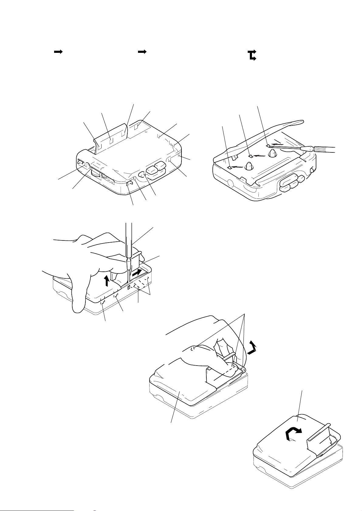
2-1. CABINET (REAR) ASSEMBLY
• The cabinet (REAR) assembly has numerious claws.
When removing it, check the positions of these claws as shown below.
CASSETTE LID
4
4
2
2
!™
4
B
!¡
!º
9
8
7
6
5
3
Slide the screwdriver (flat-blade) in
arrow
B
two claws
Note: Take note of the flexible board.
1
direction to disconnect the
2
.
Open the battery case lid.
3
1
1
A
Flexible board
!™
!¡
2
Put your second finger in the battery
case of the cabinet (REAR) assembly,
pull in the arrow
disconnect claws
A
direction to
1, !¡
and !™.
2
Cabinet (REAR) assembly
4
Disconnect claw 3. As shown in the
figure, lift up the cabinet (REAR)
assembly, pull in arrow
to disconnect the three claws
C
direction
4
4
C
Lift the cabinet (REAR) assembly
5
in the arrow
to
!º
.
D
will disconnect automatically.
direction. Claws 5
D
– 3 –
Lift the cabinet assembly, then twist across.
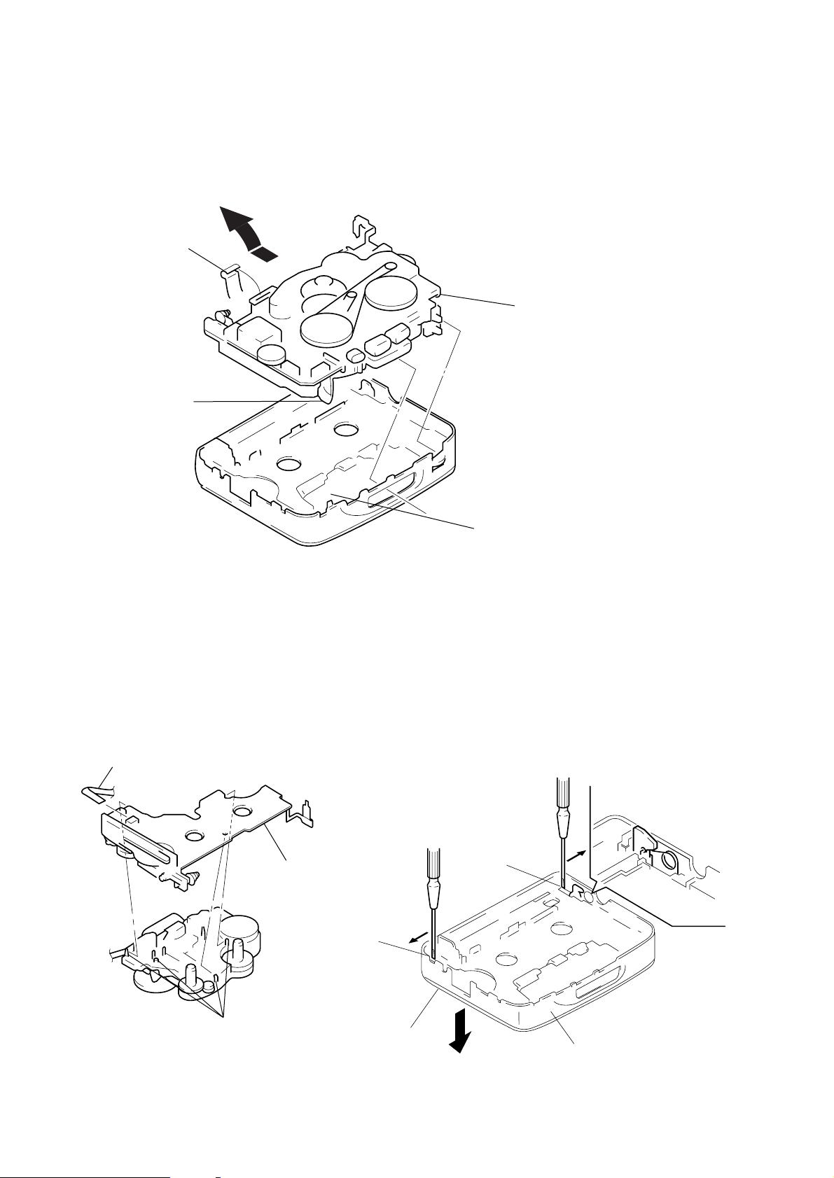
2-2. MECHANISM DECK AND MAIN BOARD
2
Remove the mechanism deck and main
board in the direction of the arrow.
1
Flexible board
Head flexible board
Mechanism deck
and MAIN board
*
*
note for installation:
Make sure to put the head
flexible board to ditch before
install the mechanism deck
and MAIN board.
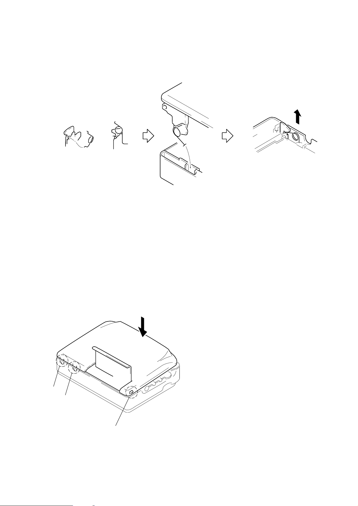
2-3. MAIN BOARD 2-4. CASSETTE LID
2
1
Head flexible board
3
Main board
1
Insert the precision screwdriver
(1.4mm flat-blade) vertically
in to portion
hinge plate.
A
to release the
Portion B to release the
hinge plate.
B
Note: Be careful not to loose
the spring here
2
Claws
A
3
Remove the cassette
lid in arrow
C
direction.
– 4 –
C
Front cabinet
2-5. NOTE FOR INSTALLATION
• TORSION SPRING
1
Attach the torsion spring as
shown the figure.
2
Insert the torsion spring in the
hole as shown in the figure.
3
Lift the torsion spring in the
arrow direction and hook it
properly.
• CABINET (REAR) ASSEMBLY
After pushing claws A to C and locking them.
Push the cabinet (REAR) assembly in the arrow direction, and lock
the order claws.
A
B
C
– 5 –
 Loading...