

Sony WMEX-655 Service manual
WM-EX655/EX668
SERVICE MANUAL
Ver 1.2 2000. 03
With SUPPLEMENT 1 (9-923-312-81)
Photo : WM-EX655
Dolby noise reduction manufactured under license from
Dolby Laboratories Licensing Corporation.
“DOLBY” and the double-D symbol a are trademarks of
Dolby Laboratories Licensing Corporation.
SPECIFICATIONS
Tape Player section and general
Frequency response (a NR switch off)
30 – 18,000Hz
Output
Headphones (2 REMOTE jack)
Load impedance 8 – 300ohms
Power output
4mW + 4mW at DC operation
Power requirements
1.5V DC
Rechargeable battery (NC-6WM), 1.2V, 600mAH, Ni-Cd) One R6
(size AA) battery
Battery life (Aprrox. hours)
Rechargeable NC-6WM 9
Fully charged
Sony R6P (SR) 9
Sony alkaline LR6 (WM) 36
Rechargeable NC-6WM 45
Sony alkaline LR6 (WM)
Used together
Dimensions
Approx. 108.9 x 80 x 21.3 mm (w/h/d)
Weight
Approx. 150g (Main unit)
Approx. 215g (incl. Headphones with remote control, Rechargeable battery NC-6WM (S), Type (C-60-HF))
AEP Model
UK Model
WM-EX668
Tourist Model
WM-EX655
Model Name Using Similar Machanism NEW
T ape Transport Mechanism T ype MT-WMEX655-125
Supplied Accessories
• Battery charger (1)
• Rechargeable battery (NC-6WM, 1.2V 600mAh, Ni-Cd) (1)
• Battery case (1) (WM-EX655)
• Stereo earphones with remote control (1) (WM-EX655)
• Carrying pouch (1)
• Rechargeable battery carrying case (1)
• Remote control unit (RM-WME654) (1)
• Sony battery R6P (SR) (1) (WM-EX655)
• AC plug adaptor (1) (WM-EX655)
• Clip (1) (WM-EX655)
Design and specifications are subject to change without notice.
MICROFILM
CASSETTE PLAYER

TABLE OF CONTENTS
Specifications .........................................................................1
1. GENERAL
Location and Function of Controls......................................... 3
2. SERVICE NOTE ........................................................ 4
3. DISASSEMBLY
3-1. Case Assy Removal.........................................................6
3-2. Audio Board Removal.....................................................6
3-3. Cassette lid Assy Removal.............................................. 7
3-4. Mechanism Deck Removal ............................................. 7
4. ADJUSTMENTS
4-1. Mechanical Adjustments.................................................8
4-2. Electrical Adjustments .................................................... 8
5. DIAGRAMS
5-1. Explanation of IC Terminals ...........................................9
5-2. Printed Wiring Boards...................................................12
5-3. Schematic Diagram .......................................................15
6. EXPLODED VIEWS
6-1. Case Section ..................................................................20
6-2. Audio Board Section .....................................................21
6-3. Mechanism Deck Section (MT-WMEX655-125) .........22
7. ELECTRICAL PARTS LIST .................................. 23
Flexible Circuit Board Repairing
• Keep the temperature of the soldering iron around 270°C during
repairing.
• Do not touch the soldering iron on the same conductor of the
circuit board (within 3 times).
• Be careful not to apply force on the conductor when soldering or
unsoldering.
Notes on chip component replacement
• Never reuse a disconnected chip component.
• Notice that the minus side of a tantalum capacitor may be damaged by heat.
– 2 –
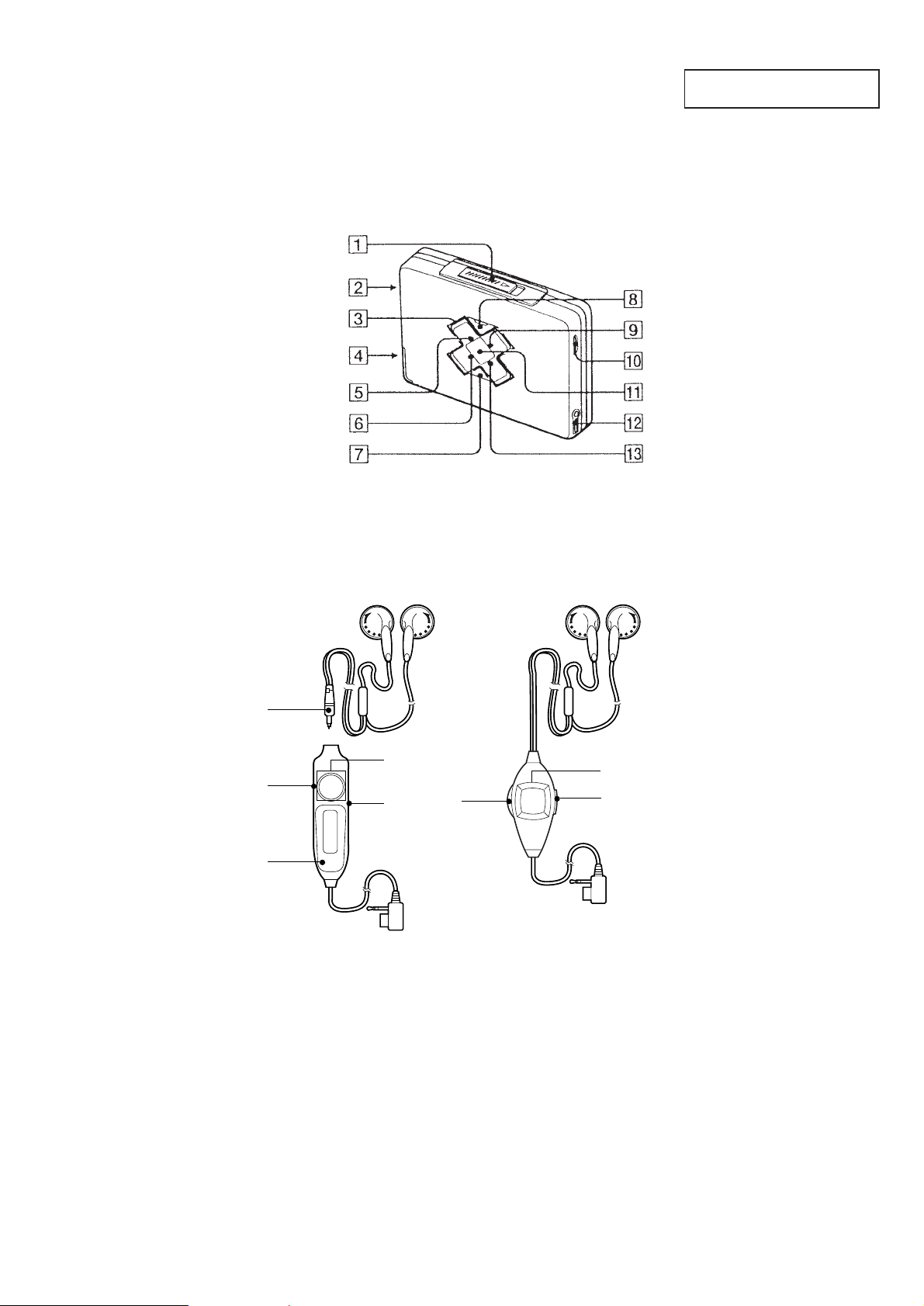
LOCATION AND FUNCTION OF CONTROLS
t
Tape player section and general
r
Main unit
SECTION 1
GENERAL
This section is extracted from
instruction manual.
r
Headphones with Remote Control
!∞
!º
!¢
1 OPEN knob
2 Contact for dry battery case
3 Tape operation buttons
4 Rechargeable battery case
5 BL SKIP indicatior
6 AVLS indicatior
7 FUNCTION button
8 HOLD switch
9 MB/GRV (Mega Bass/Groove) indicator
WM-EX655
Left Right
3
8
!º
WM-EX668
Left Righ
3
8
0 Main unit : VOLUME knob
Remote control : VOL knob
!¡ BATT indicator
!™ 2 REMOTE jack
!£ a (DOLBY) NR indicator
!¢ SOUND/AVLS (Auto Volume limitter
system) switch
!∞ Micro plug
– 3 –
SECTION 2
SER VICE NOTE
SERVICE MODE
Mode which enables the mechanism to be operated with the AUDIO board opened.
This set detects the rotation of GEAR (S) using the PH701 (photo
reflector). The PH701 is mounted on the AUDIO board, and therefore the GEAR cannot be detected with the AUDIO board removed.
As a result, the motor cannot be controlled, causing malfunction.
Further, the S702 (FWD/REV switch) is also mounted on the AUDIO board, and with the board removed, the mechanism position
cannot be detected and the operation is not changed over.
Therefore, when the voltage check is executed with the AUDIO
board removed, follow the procedure provided below.
Note :Do not move the S702 switch position when removing the
AUDIO board.
If it is moved, the set will not be changed over to the selected mode. In this case, reconnect the AUDIO board to
the set and retry the work from the beginning.
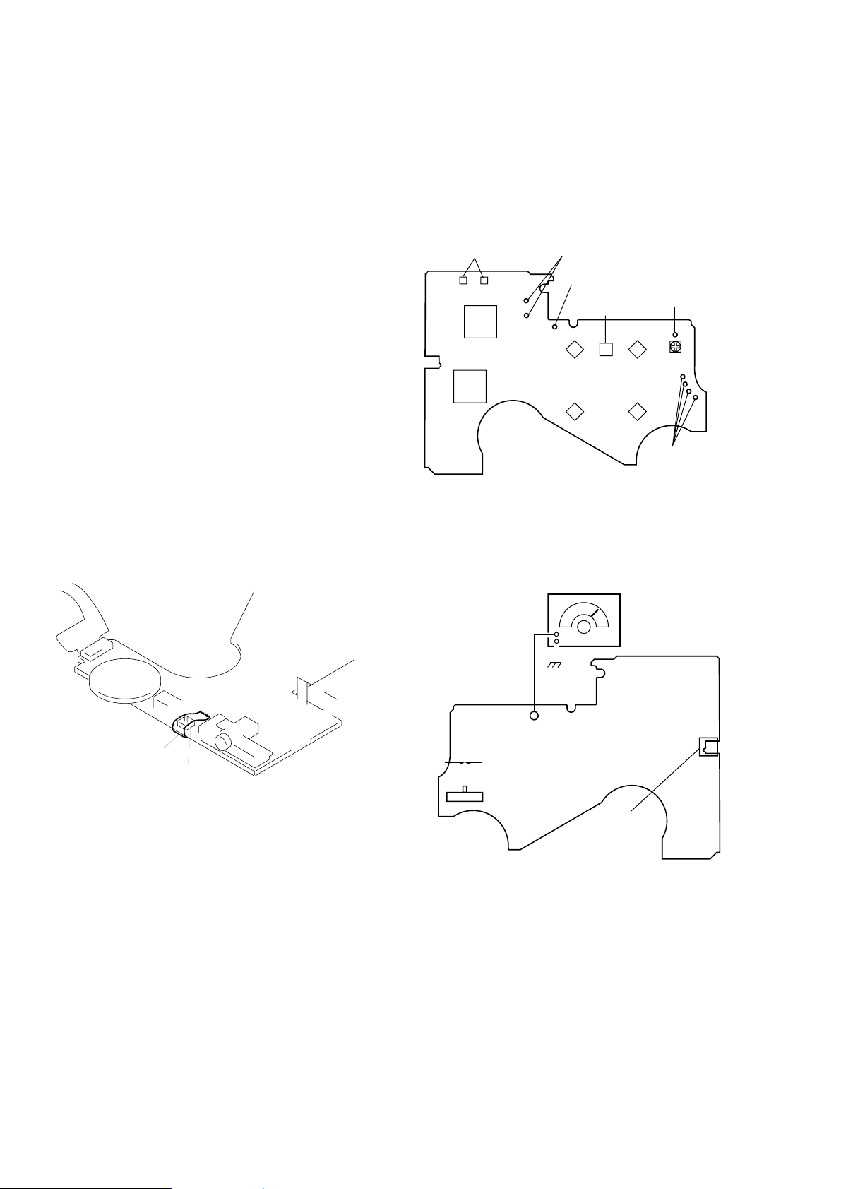
1. Setting
1) Refer to “3. DISASSEMBLY”, and remove the case and open
the AUDIO board.
2) Connect the AUDIO board to the M901 (motor) and PM901
(plunger) using a jumper wire. (See Fig- 2)
3) Short the ATS terminals (S901).
4) Press and fixed the S701 (HOLDER SW). (See Fig- 1)
3. PLAY Mode
1) Input a square wave to the TP35 (PHOTO IN). (See Fig-3)
2) Press the S704 (STOP) for selecting STOP mode.
3) Press the S705 (PLAY). (Each time the switch is pressed, the
mode is chaged over.)
[AUDIO board ] (Side A)
ATS terminals
(S901)
IC701
IC301
connect to plunger (PM901)
battery terminal
S708
(FUNCTION)
S704
(
p
)
S705
(
9(
S707
(REW )
)
S706
(FF)
’
battery terminal
connect to
motor (M901)
(Fig - 2)
‘
[AUDIO board ] (Side B)
Tape
S701
(HOLDER SW)
(Fig - 1)
5) Supply 1.5V to the battery terminals ‘ and ’ using a stabilized
power supply.
2. FF, REW Modes
1) Input a square wave to the TP35 (PHOTO IN). (See Fig-3)
2) Press the S704 (STOP) for selecting STOP mode.
3) Press the S706 (FF) or S707 (REW).
[AUDIO board ] (Side B)
square wave signal
10Hz, –3.5dB
TP35
Center
F side R side
S702
(F/R SW)
audio frequency
generator
S701
(HOLDER SW)
(Fig - 3)
– 4 –
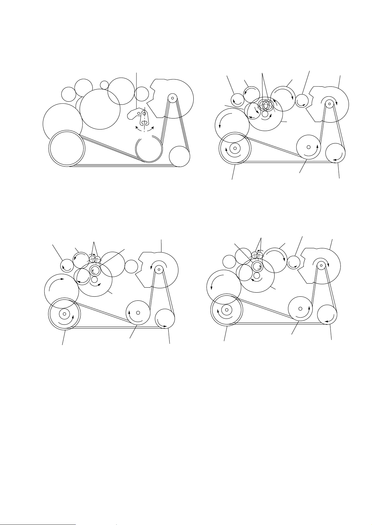
LEVER (SW )
)
Gear (Reel)
(T side)
Gear (Reel)
(S side)
Gear (TA)
Gear (TB)
Gear (S)
Gear (Y)
Gear (NR)
(REV : Left side/
FWD : Right side)
Motor Pully
Flywheel (N) Assy
Flywheel (R) Assy
Pully (Reverse)
Clutch
Assy (M)
Gear (Reel)
(S side)
Gear (FR)
(REW : Right side)
Gear (S)
Gear (Y)
Gear (NR)
Motor Pully
Clutch Assy (M)
Flywheel (N) Assy
Flywheel (R) Assy
Pully (Reverse)
Rortation system during PLAY.
lever (SW)
Rortation system during FF.
Gear (Reel)
(T side)
Gear (Y)
Gear (FR)
(FF : Left side)
Gear (TB)
side R
center
Gear (NR)
Clutch Assy (M)
side F
Rortation system during REW.
Motor pully
Flywheel (N) Assy
Flywheel (R) Assy
Pully (Reverse
– 5 –
r
SECTION 3
DISASSEMBLY
r
The equipment can be remo ved using the f ollo wing pr ocedure .
Set
Case assy
Audio board
Cassette lid assy
Note : Follow the disassembly procedure in the numerical order given.
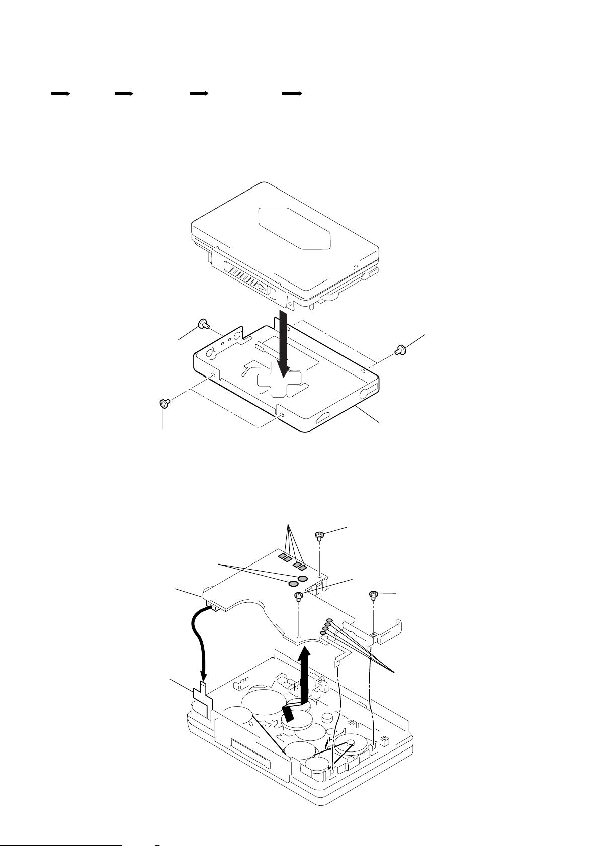
3-1. CASE ASSY REMOVAL
1
Screw (IB lock)
Mechanism deck
3
1
Screws (IB lock)
2
3-2. AUDIO BOARD REMOVAL
3
Remove solder
Audio board
6
Head flexible board
Screws (IB lock)
4
Remove solder
7
Case assy
1
Screw
2
Screw (IB lock)
1
Screw
5
Remove solde
– 6 –
 Loading...