

SONY WM EX422 Service Manual
WM-EX422
SERVICE MANUAL
Ver 1.1 2003.12
Model Name Using Similar Mechanism NEW
MD Mechanism Type MF-WMFX495-147
SPECIFICATIONS
E Model
• Frequency response
Playback: 30 - 18 000 Hz
• Output
Headphones (i) jack Load impedance 8 - 300 Ω
• Power requirements
1.5V DC, battery R6 (AA) x 1
• Dimensions (w/h/d)
Approx. 111.2 x 81.1 x 29.5 mm (4 1⁄2 x 3 1⁄4 x1 3⁄16 in.), excl.
projecting parts and controls
• Mass
Approx. 124 g (4.4 oz) (main unit only)
• Supplied accessories
Stereo headphones or earphones (1)
Hand strap (1) (European model only)
Carrying pouch (1) (Asian model only)
Design and specifications are subject to change without notice.
Battery life* (approximate hours)
Sony alkaline LR6 (SG)** Sony R6P (SR)
Tape playback 35 9
* Measured value by the standard of JEITA (Japan Electronics and
Information Technology Industries Association).
(Using a Sony HF series cassette tape)
**When using a Sony LR6(SG) “STAMINA” alkaline dry battery
(produced in Japan).
Note
• The battery life may be shorter depending on the operating condition, the
surrounding temperature and battery type.
9-877-095-02
2003L02-1
© 2003.12
CASSETTE PLAYER
Sony Corporation
Personal Audio Company
Published by Sony Engineering Corporation

WM-EX422
TABLE OF CONTENTS
Specifications ........................................................................... 1
1. SERVICING NOTE ...................................................... 3
2. GENERAL ...................................................................... 4
3. DISASSEMBLY
3-1. Cabinet (Front)Sub Assy ............................................ 5
3-2. Main Board ................................................................. 6
3-3. Mechanism Deck ........................................................ 6
3-4. Cassette Holder Sub Assy........................................... 7
4. ADJUSTMENTS
4-1. Mechanical Adjustments ............................................ 8
4-2. Electrical Adjustments ................................................ 8
5. DIAGRAMS
5-1. Block Diagram ............................................................ 9
5-2. Printed Wiring Boards .............................................. 10
5-3. Schematic Diagram .................................................... 11
5-4. IC Block Diagrams ................................................... 12
6. EXPLODED VIEWS
6-1. Cabinet Section ......................................................... 13
6-2. Mechanism Deck Section
(MF-WMFX495-147) ....................... 14
Flexible Circuit Board Repairing
• Keep the temperature of the soldering iron around 270°C during
repairing.
• Do not touch the soldering iron on the same conductor of the
circuit board (within 3 times).
• Be careful not to apply force on the conductor when soldering or
unsoldering.
Notes on chip component replacement
• Never reuse a disconnected chip component.
• Notice that the minus side of a tantalum capacitor may be damaged by heat.
7. ELECTRICAL PARTS LIST ................................... 15
2
SECTION 1
p
SERVICING NOTES
WM-EX422
This set detects the rotation of the idler gear (A) (side S) using the
photo reflector (PH751). The PH751 is mounted on the MAIN
board, therefore the idler gear (A) (side S) cannot be detected with
the MAIN board removed. As a result, the motor (M601) cannot
be controlled, causing malfunction.
Further, the MD switch (S601) is also mounted on the MAIN board,
and with the board removed, the mechanism position cannot be
detected and the operation is not changed over.
Therefore, when the voltage check is executed with the MAIN
board removed, follow the procedure provided below.
1. Setting
1) Refer to “3. DISASSEMBLY”, and remove the MAIN board.
2) Connect the MAIN board to the motor (M601) using jumper
wires. These can be connected easily with the use of the
extension tool (Part No. 1-769-143-11) (ten in one set).
3) Connect the AF oscillator to the TP52 and the BT401 (BATT–
).
4) Supply 1.5 V to the battery terminals using the regulated power
supply.
2. Preset state
To set the PLAY, FF, REW modes, the preset state must be set.
1) Check that the slider (NRA) and the MD switch (S601) are set
to the center position. If not, set the preset state as follow.
2) Move the MD switch (S601) to the side, which the slider (NRA)
is facing.
3) The slider (NRA) will move when the regulated power supply
switch is set to OFF once and then set to ON. Move the MD
switch (S601) according to this timing and set to the center
position.
3. FF, REW modes
1) Check that the preset state is set.
2) Input the square wave or sine wave to the TP52 and the BT401
(BATT–).
3) Press the [FF] button or [REW] button .
4. PLAY mode
1) Check that the preset state is set.
2) Input the square wave to the TP52 and the BT401 (BATT–).
3) Press the Y button will move the slider (NRA) once towards
the side REV and then to the side FWD. Move the MD switch
(S601) according to this timing will set the PLAY mode (side
FWD). Press the Y button another time for a second and
move the MD switch (S601) according to the movement of
the slider (NRA) will set the PLAY mode (side REV).
Note 1: If the above fails, perform from preset again.
Note 2: When using headphones, the timing for move the MD
switch (S601) can be determined from the beep sound.
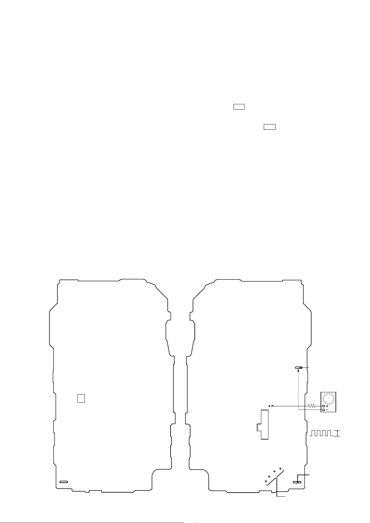
— MAIN Board (Component Side) — — MAIN Board (Conductor Side) —
PH751
TP52
(PHOTO)
RVS
tt
REW
t
FF
FWD
S601
(MD CONT)
BT401
battery terminal
AF oscillator
square wave
2 Hz, 2 VdB
#
2Vp-
battery
terminal
3
connect to themotor (M601)
3
WM-EX422
SECTION 2
GENERAL
This section is extracted from
instruction manual.
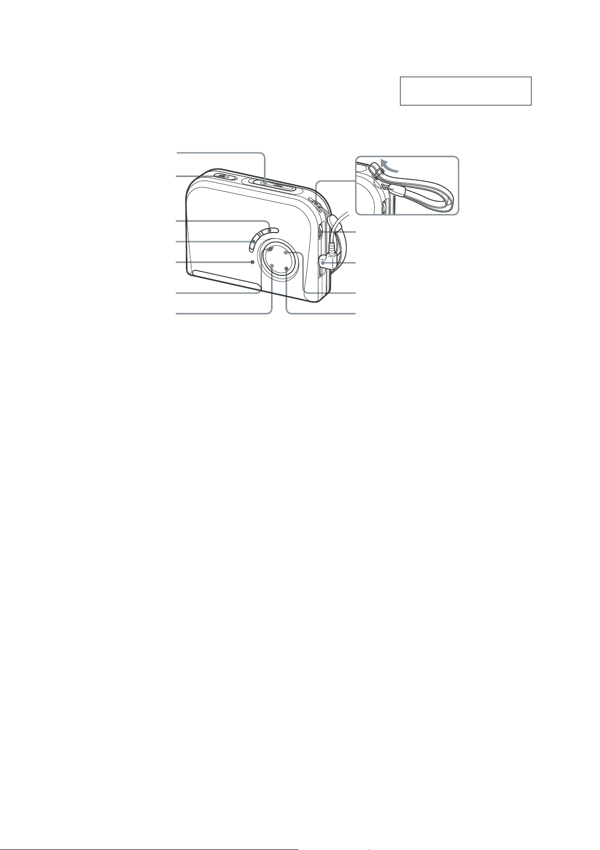
To attach the hand strap*
OPEN
HOLD
AVLS
VOL**
MEGA BASS
BATT
Y•DIRECTION***
REW
* Supplied with the European model only.
** There is a tactile dot beside VOL to show the direction to turn up the volume.
*** The button has a tactile dot.
i
FF
x
4
DISASSEMBLY
y
z
The equipment can be removed using the following procedure.
WM-EX422
SECTION 3
Set
Cabinet (front) sub assy
MAIN boardCabinet center
Cassette holder sub assy
Note : Follow the disassembly procedure in the numerical order given.
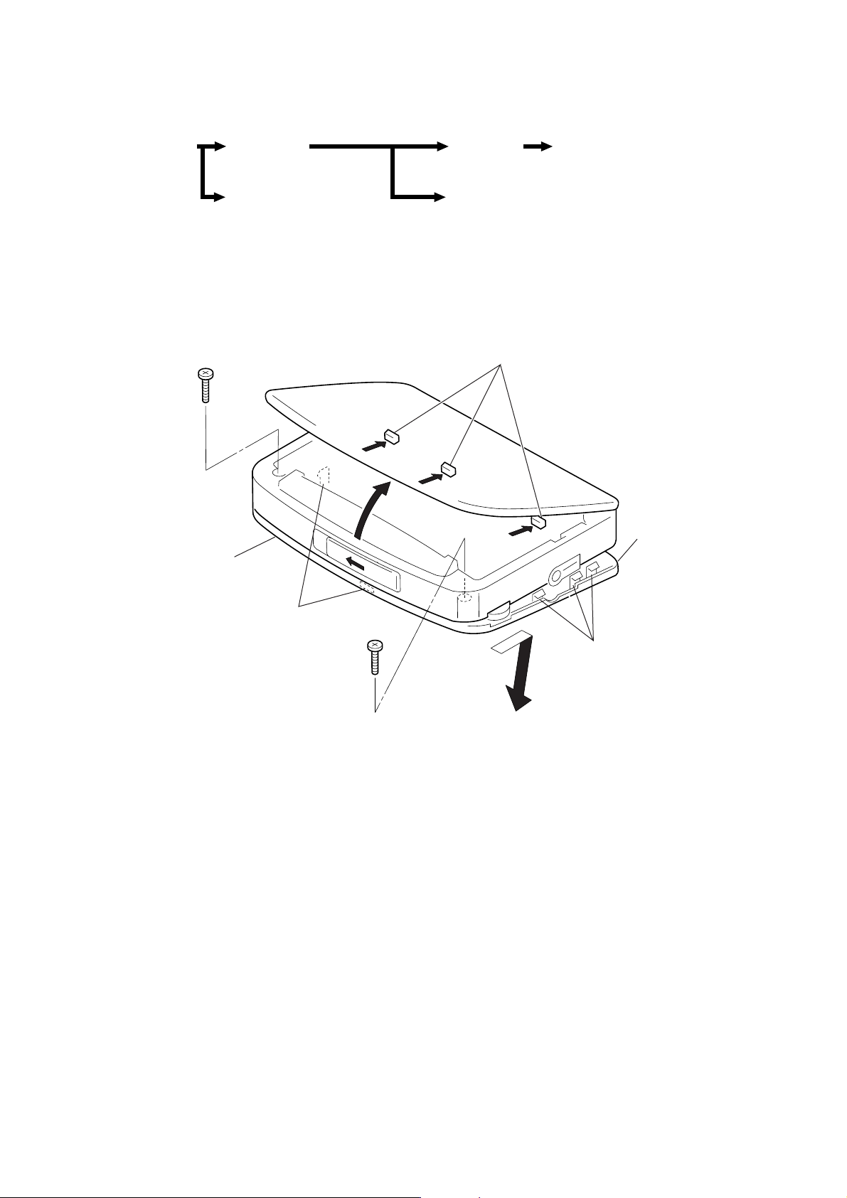
3-1. CABINET (FRONT) SUB ASSY
2
Screw (B 1.7 × 9), tapping
1
Cabinet center
4
Claws
Mechanism deck
8
Cabinet (front) sub ass
6
Claws
3
Screw (B 1.7 × 9), tapping
7
5
Claws
5
WM-EX422
y
r
3-2. MAIN BOARD
6
MAIN board
3
Screw (1.7 × 2.5), tapping
5
2
Unsolder leads from moto
(four places)
1
Unsolder HEAD flexible board
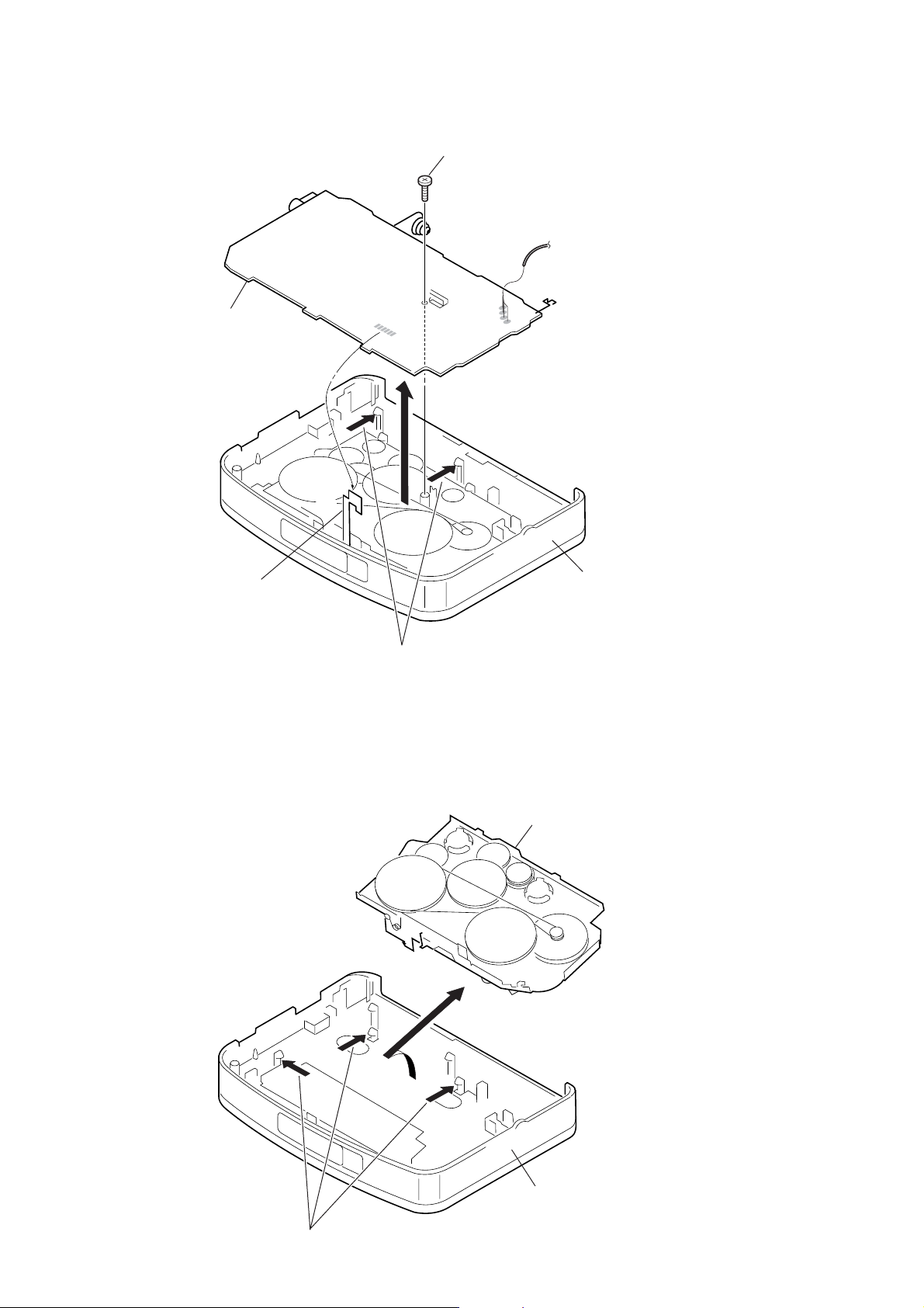
3-3. MECHANISM DECK
4
Claws
2
3
Mechanism deck
Cabinet (center) assy
Cabinet (center) ass
1
Claws
6
 Loading...