

Sony WMEX-372 Service manual
WM-EX372
SERVICE MANUAL
Ver 1.2 1999. 03
With SUPPLEMENT 1
(9-923-319-81)
With SUPPLEMENT 2
(9-923-319-82)
Dolby noise reduction manufactured under license
from Dolby Laboratories Licensing Corporation.
“DOLBY” and the double-D symbol a are trademarks of Dolby Laboratories Licensing Corporation.
SPECIFICATIONS
AEP Model
E Model
TC-K6/K7
Model Name Using Similar Mechanism NEW
Tape Transport Mechanism Type MT-WMEX372-114
MICROFILM
CASSETTE PLAYER

TABLE OF CONTENTS
1. GENERAL ................................................................... 3
2. DISASSEMBLY ......................................................... 4
3. MECHANICAL ADJUSTMENTS....................... 8
Flexible Circuit Board Repairing
• Keep the temperature of the soldering iron around 270 ˚C during repairing.
• Do not touch the soldering iron on the same conductor of the
circuit board (within 3 times).
• Be careful not to apply force on the conductor when soldering
or unsoldering.
4. ELECTRICAL ADJUSTMENTS......................... 8
5. DIAGRAMS
5-1. Block Diagram ................................................................ 9
5-2. Printed Wiring Board ...................................................... 11
5-3. Schematic Diagram ......................................................... 13
6. EXPLODED VIEWS ................................................ 16
7. ELECTRICAL PARTS LIST ............................... 19
Notes on chip component replacement
• Never reuse a disconnected chip component.
• Notice that the minus side of a tantalum capacitor may be damaged by heat.
– 2 –
SECTION 1
GENERAL
This section is extracted from
instruction manual.
– 3 –
• This set can be disassembled in the order shown below.
R
y
SECTION 2
DISASSEMBLY
SET
Note: Follow the disassembly procedure in the numerical order given.
CABINET (REAR) ASS’Y MECHANISM DECK
MAIN BOARD
(MT-WMEX372-114)
CASSETTE HOLDER ASS’Y
MEGA BASS UNIT (DOLBY)
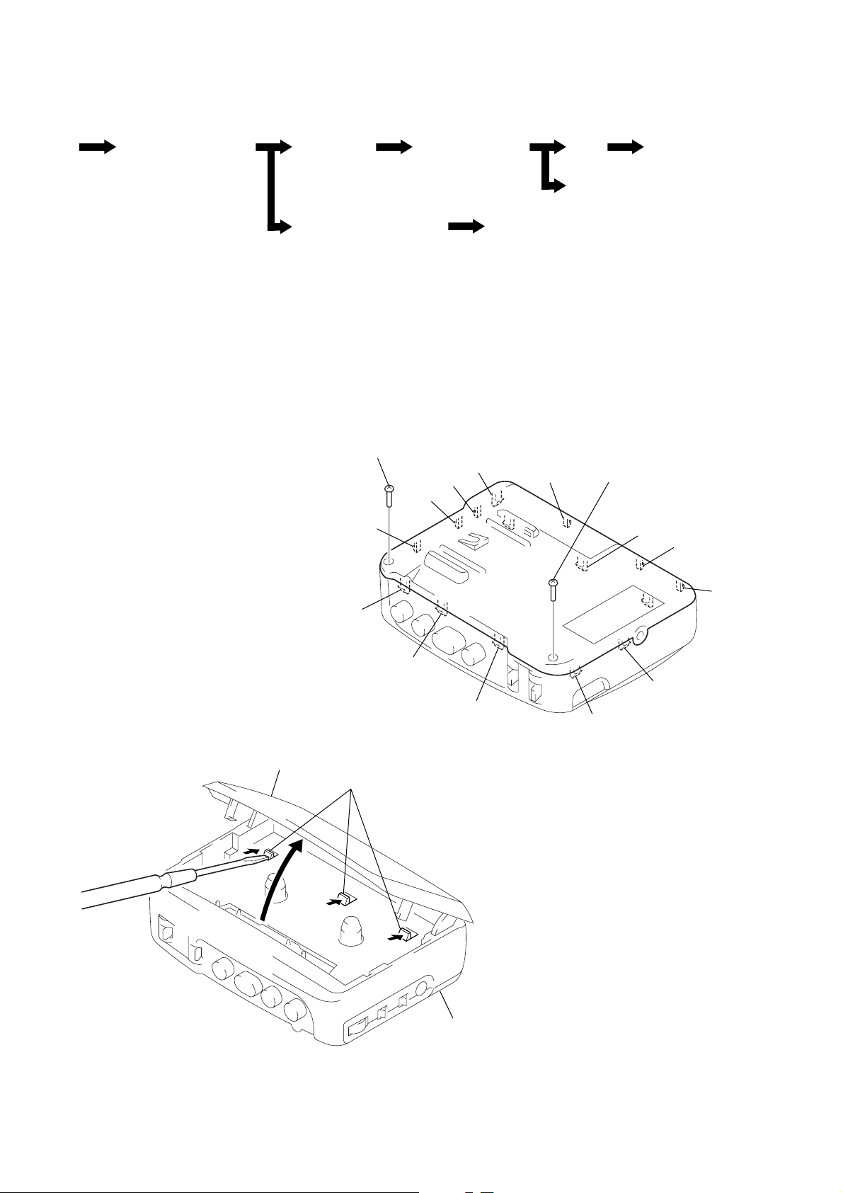
CABINET (REAR) ASS’Y
2
Insert the precision screw driver (1.4 mm flat-blade) in to the slit at claw A and release the claw.
3
Remove the cabinet (rear) ass’y. (Release all claw B to N in alphabetical order.)
1
screw (B1.7 × 9)
N
M
L
K
BELT
MAGNETIC HEAD
(HP901)
B
MOTO
(M901)
1
screw (B1.7 × 9)
C
D
cassette holder
E
J
I
F
H
G
A
– 4 –
cabinet (rear) ass’
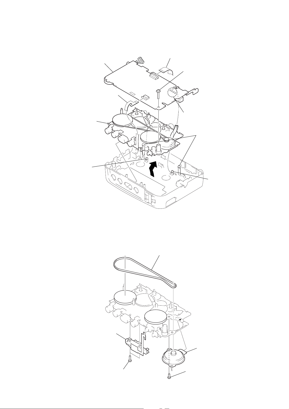
MAIN BOARD, MECHANISM DECK (MT-WMEX372-114)
w
s
6
main board
3
head flexible board
(CN301)
8
Remove the mechanism
deck (MT-WMEX372-114)
to direction of the arrow.
7
claw
2
flexible board (CN302)
4
toothed lock (WH) scre
(M1.4)
1
Remove four solders of
motor lead (M901).
5
two claws
BELT, MOTOR (M901), MAGNETIC HEAD (HP901)
1
belt
7
claw
5
magnetic head
(HP901)
4
two screws
– 5 –
3
motor (M901)
2
two special head screw
(M1.4)
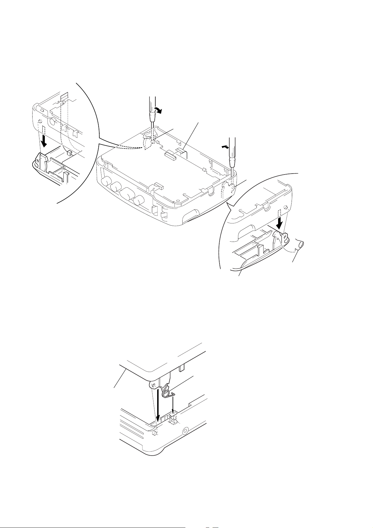
CASSETTE HOLDER ASS’Y
2
Insert a precision screwdriver (1.4 mm flat-blade)
vertically in to portion A to release the hinge plate.
1
flexible board
(CN302)
A
3
portion B to release
the hinge plate.
B
NOTE FOR INSTALLATION
Note: Follow the assembly procedure in the numerical order given.
• SPRING (TORSION)
3
cassette holder ass’y
A
4
cassette holder ass’y
1
Attach the spring (torsion) as
shown in the figure.
2
Insert the spring (torsion) in the
ditch to direction of the arrow
5
spring (torsion)
A
.
– 6 –
 Loading...