

Sony WMEX-2000 Service manual
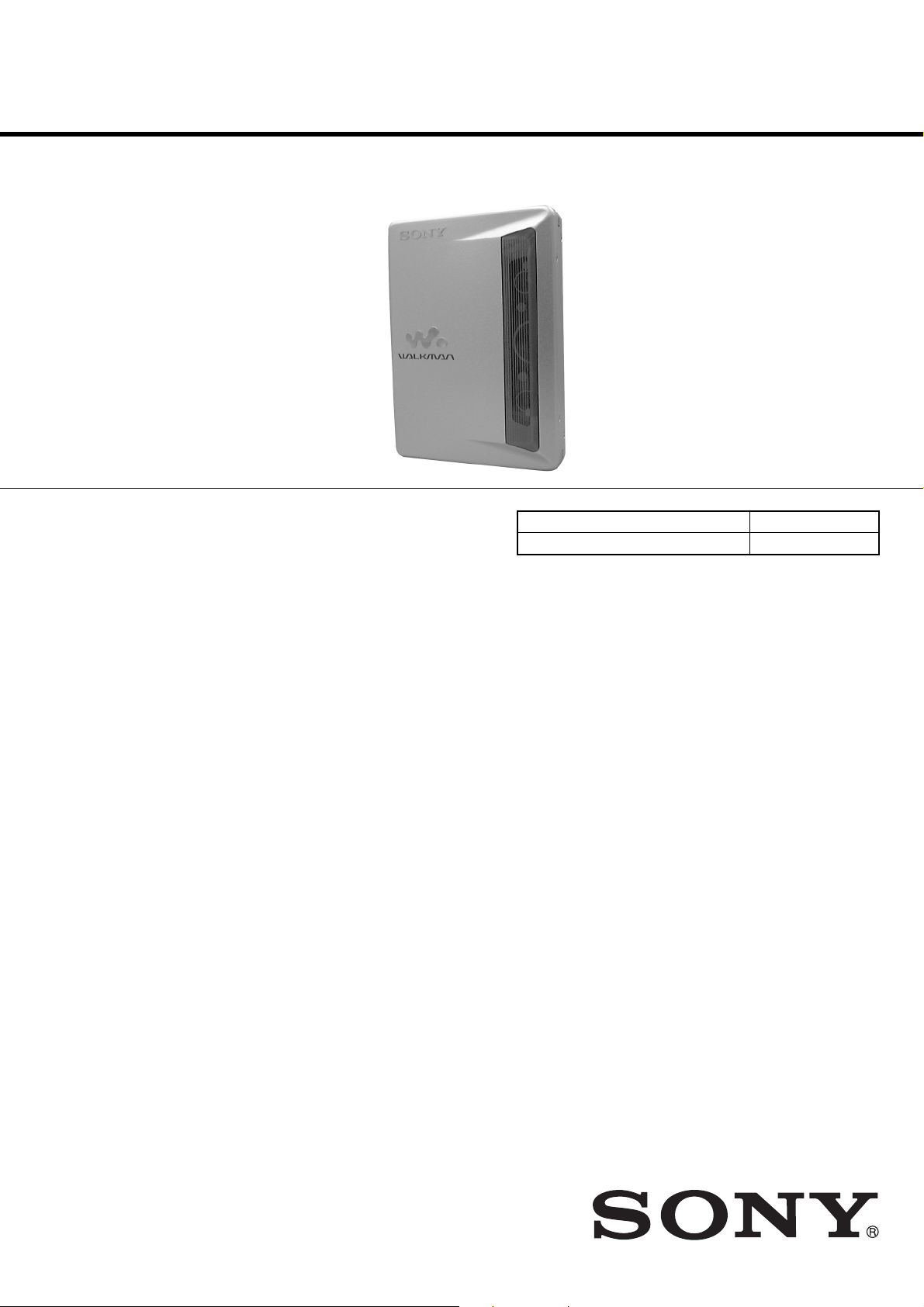
WM-EX2000
SERVICE MANUAL
Ver 1.2 2003. 11
Manufactured under license from Dolby Laboratories
Licensing Corporation.
“DOLBY” and the double-D symbol ; are trademarks
of Dolby Laboratories Licensing Corporation.
SPECIFICATIONS
US Model
AEP Model
Chinese Model
E Model
Tourist Model
Model Name Using Similar Mechanism NEW
Tape T ransport Mechanism T ype MT -WMEX2000-162
Frequency response
(Dolby NR off) Playback: 30 – 18,000 Hz
Output Headphones (i jack)
Load impedance 8 – 300 Ω
Power requirements 1.2 V
One rechargeable battery
Dimensions (w/h/d) Approx. 76.3 × 108.4 × 17.5 mm
(31/8 × 43/8 × 23/32 inches)
Mass Approx. 145 g (5.2 oz.)
Supplied accessories Stereo headphones or earphones with
remote control (1)
Battery charging stand (1)
AC power adaptor (1)
Rechargeable battery (NH-14WM (A),
1.2V, 1 350 mAh (MIN), Ni-MH) (1)
Rechargeable battery carrying case (1)
Carrying pouch (1)
Design and specifications are subject to change without notice
9-873-022-13
2003K16-1
© 2003.11
CASSETTE PLAYER
Sony Corporation
Personal Audio Company
Published by Sony Engineering Corporation
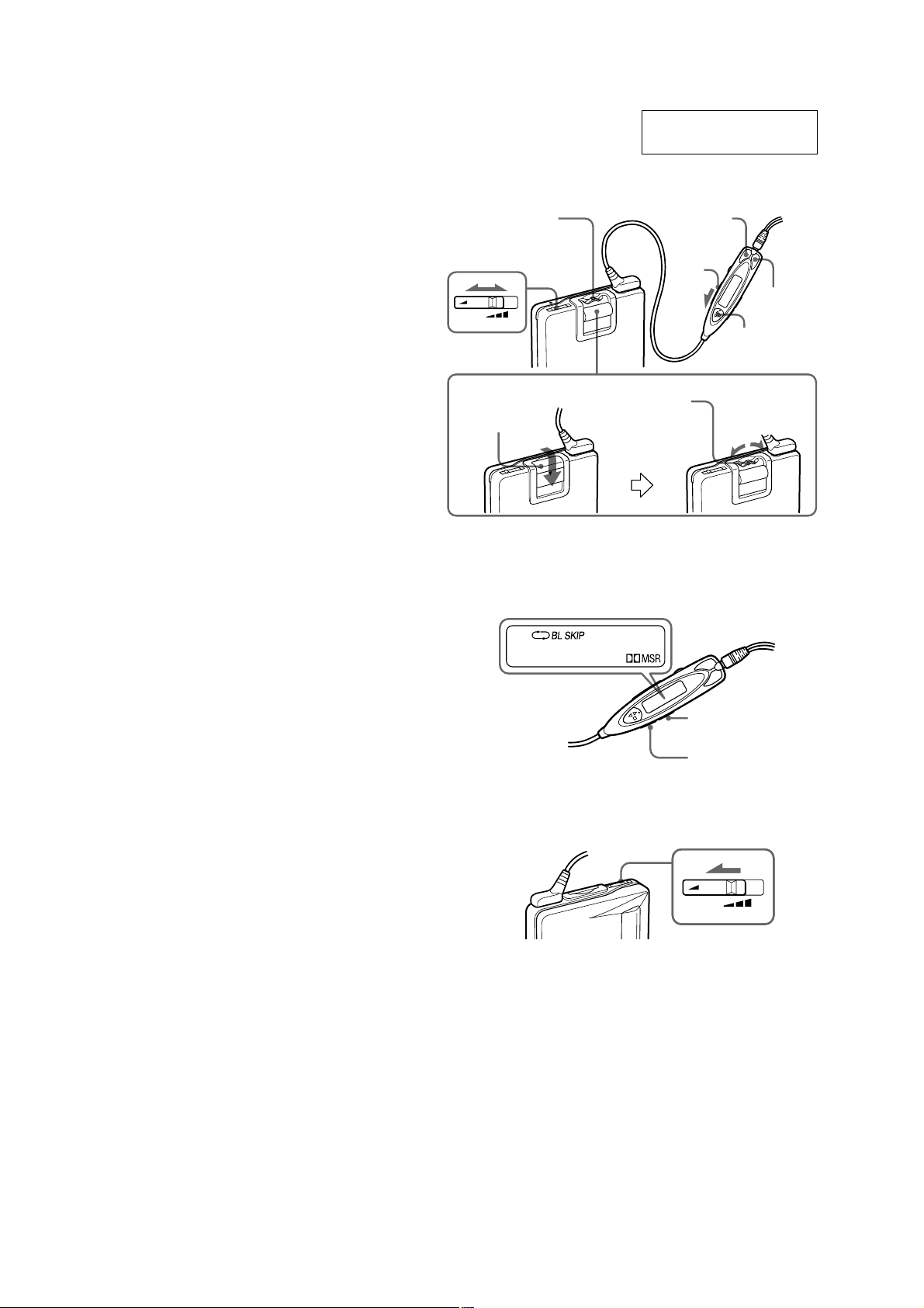
TABLE OF CONTENTS
1. GENERAL ·········································································· 2
2. SERVICE NOTE ······························································· 3
3. DISASSEMBLY
3-1. Lid Block Assy, Cassette ················································ 5
3-2. Case Block Assy ····························································· 5
3-3. Ornament (Open) Block Assy·········································6
3-4. “Switch, Leaf (S704)”, Main Board ······························· 6
3-5. Belt (F0), Motor (M601)·················································7
3-6. Holder (FA) Assy ···························································· 7
3-7. Pinch Lever (NF)/(RF) Assy ··········································· 8
3-8. Head, Magnetic (HP701) ················································8
4. MECHANICAL ADJUSTMENT ·································· 9
VOL
AVLS
Jog lever
Levier Jog
Jog-Hebel
SECTION 1
GENERAL
This section is extracted
from instruction manual.
Plug in firmly.
Branchez fermement.
Fest einstecken.
FF (+)
HOLD
REW (–)
Y•x
5. ELECTRICAL ADJUSTMENT ···································· 9
6. DIAGRAMS
6-1. Block Diagram ······························································ 10
6-2. Printed Wiring Board···················································· 12
6-3. Schematic Diagram (1/2) ·············································· 15
6-4. Schematic Diagram (2/2) ·············································· 18
6-5. IC Block Diagrams ······················································· 21
6-6. IC Pin Function Description ·········································23
7. EXPLODED VIEWS
7-1. Cabinet Block ······························································· 24
7-2. Mechanism Deck Block ················································ 25
8. ELECTRICAL PARTS LIST ·······································26
Hold shutter
Cache de
verrouillage
Schutzschieber
Jog lever
Levier Jog
Jog-Hebel
N
E
P
O
SOUND
MODE
REW
FF
Notes on chip component replacement
• Never reuse a disconnected chip component.
• Notice that the minus side of a tantalum capacitor may be
damaged by heat.
Flexible Circuit Board Repairing
• Keep the temperature of soldering iron around 270˚C
during repairing.
• Do not touch the soldering iron on the same conductor of the
circuit board (within 3 times).
• Be careful not to apply force on the conductor when soldering
or unsoldering.
SAFETY-RELATED COMPONENT WARNING!!
COMPONENTS IDENTIFIED BY MARK 0 OR DOTTED LINE WITH
MARK 0 ON THE SCHEMATIC DIAGRAMS AND IN THE PARTS
LIST ARE CRITICAL TO SAFE OPERATION. REPLACE THESE
COMPONENTS WITH SONY PARTS WHOSE PART NUMBERS
APPEAR AS SHOWN IN THIS MANUAL OR IN SUPPLEMENTS
PUBLISHED BY SONY.
VOL
AVLS
— 2 —
SECTION 2
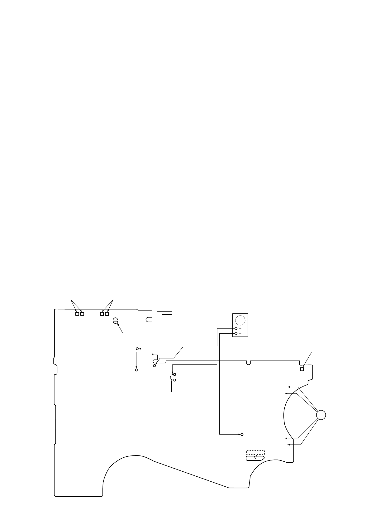
SERVICE NOTE
[Service Mode]
The service mode enables to operate the mechanism of WM-EX2000
while the MAIN board is opened.
Rotation of the idler gear (A) (S side) is detected using the photoreflector (PH702) in the WM-EX2000. PH702 is located on the
MAIN board, therefore the rotation of the idler gear (A) (S side)
cannot be detected by PH702 when the MAIN board is removed.
As a result, the motor cannot be controlled and cannot run correctly .
To repair the machine after the MAIN board is removed while the
main power is turned on, follow the procedures as described below.
1. Setting
1) Remove the cabinets referring to section “3. DISASSEMBL Y”.
Open the MAIN board.
2) Connect the motor (M601) and the plunger solenoid (PM701)
to the MAIN board using the jumper wires. When the extension
jig (1-769-143-11) (10 wires as a set) is used, they can be
connected easily.
3) Short the T APE IN switch land (BP1) with solder . Input a square
(or sine) wave of 10 Hz (at 1.3 Vp-p) to both PH IN T land
(TP31) and PH IN S land (TP32) with jumper wire.
4) Connect DC 1.3 V from e xternal regulated power supply to 3
and # terminals of the battery.
2. PRE-SET status
The set must be in this state before the PLAY, FF and REW modes
can be entered.
1) Make sure that the slider (F/R) is in the center position and that
the F/R switch (S702) is in the center position. Make sure that
the reel gear does not rotate by rotating the flywheel on the F
side clockwise. If improper, place the set in the preset state
according to the following instructions:
2) Repeat the step below some times to ensure the above
conditions.
* Pull away the trigger level from the plunger with tweezers or
other means. Then rotate the flywheel on the F side clockwise.
3) Turn the stabilized power supply OFF once and then ON.
3. FF, REW modes
1) Check for “2. Preset state” and push the FF switch and the
REW switch.
2) Move the F/R switch (S702) to the movement of the slider to
enter the FF/REW mode.
4. PLAY mode
1) Check for “2. Preset state”.
2) Push the nN switch on the remote commander to move the
lever (SW) toward the R side . With timing to this, move the F/
R switch (S702) to enter the PLAY (R side) mode.
Note 1: If failed, retry from the preset state.
Note 2: The nN, x, FF, and REW switches on the remote
commander should be used whenever possible.
– MAIN BOARD (SIDE B) —
TAPE IN
SWITCH
(S704-1)
SWITCH
(S704-2)
ATS
BP1
Plunger (PM701)
Battery terminal #
S PH IN(S)(TP32)
T PH IN(S)(TP31)
jumper
AF OSC
Square wave
(sine wave)
10 Hz, -3.5 dBs
GND (TP10)
(S702)
FWD←CNT→REV
Battery terminal 3
M
M601
— 3 —
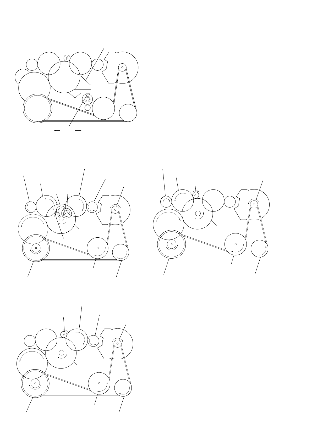
[ Slider (NR) ]
y
y
F side
flywheel
F side center R side
[ Rotational system ]
1. Rotational System of PLAY Mode
idler gear (A) (S side)
gear (reel) (T side)
idler gear (A) (T side)
gear (NR)
FWD
REV
gear (reel) (S side)
slider (NR)
motor pulle
2. Rotational System of FF Mode
gear (reel) (T side)
idler gear (A) (T side)
motor pulley
gear (FR)
gear (Y)
idler gear (B)
flywheel (N) assy
clutch
assy (F)
flywheel (R) assy
3. Rotational System of REW Mode
idler gear (A) (S side)
gear (FR)
gear (Y)
gear (reel) (S side)
clutch
assy (F)
reverse pulley
motor pulle
gear (Y)
flywheel (N) assy
clutch
assy (F)
flywheel (R) assy
reverse pulley
flywheel (N) assy
flywheel (R) assy
reverse pulley
— 4 —
SECTION 3
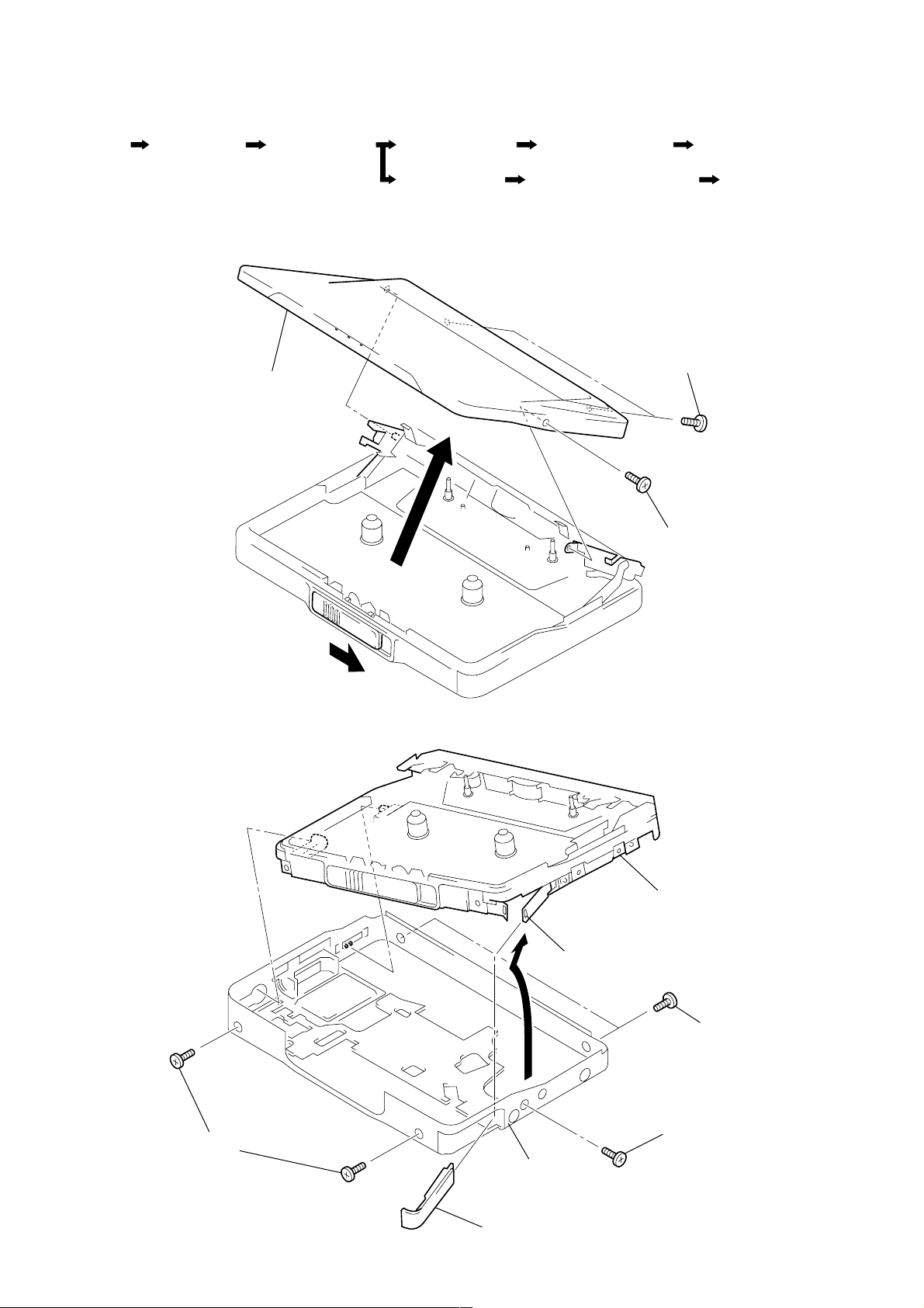
DISASSEMBLY
• The equipment can be removed using the following procedure.
Lid Block Assy,
Cassette
Note : Follow the disassembly procedure in the numerical order given.
Case Block Assy
3-1. LID BLOCK ASSY, CASSETTE
Lid block assy, cassette
Ornament (OPEN)
Block Assy
Holder (FA) Assy Pinch Lever (NF)/(RF) Assy Head, Magnetic (HP701)
"Switch, Leaf (S704)"
Main Board
Belt (F0), Motor (M601)Set
1 Two screws (1.4)
3-2. CASE BLOCK ASSY
3
4
5
2 Screw (1.4)
Mechanism deck block
Claw
2 Two screws (1.4)
3 Two screws (1.4)
4 Screw (1.4)
Case block assy
1 Lid, battery case
— 5 —
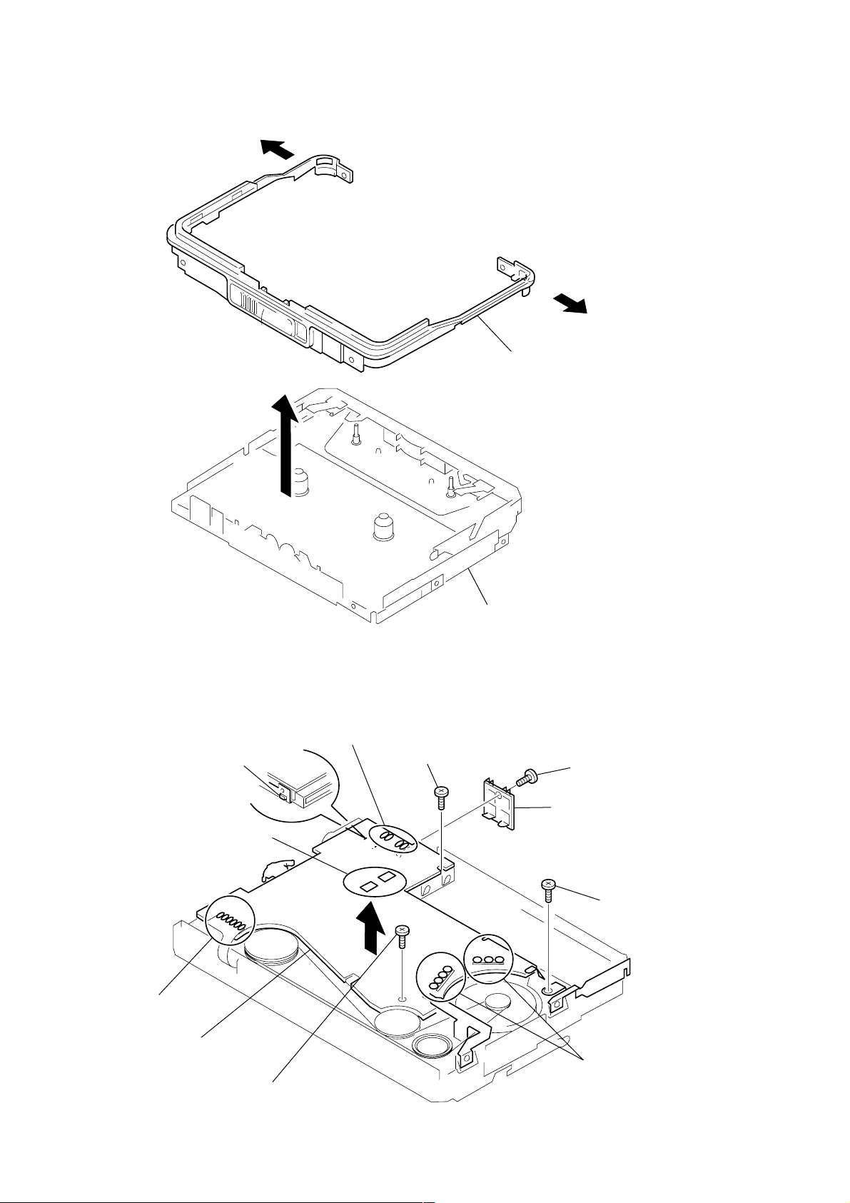
3-3. ORNAMENT (OPEN) BLOCK ASSY
y
1
2
1
Ornament (open) block ass
3-4. “SWITCH, LEAF (S704)”, MAIN BOARD
4 Unsolder the 4 places.
0 Claw
7 Unsolder the
plunger.
8 Unsolder the
flexible board.
Mechanism deck block
1 Screw
5 Screw (M1.4)
6 Switch leaf (S704)
3 Screw
qa MAIN board
9 Unsolder the motor.
2 Screw (M1.4)
— 6 —
r
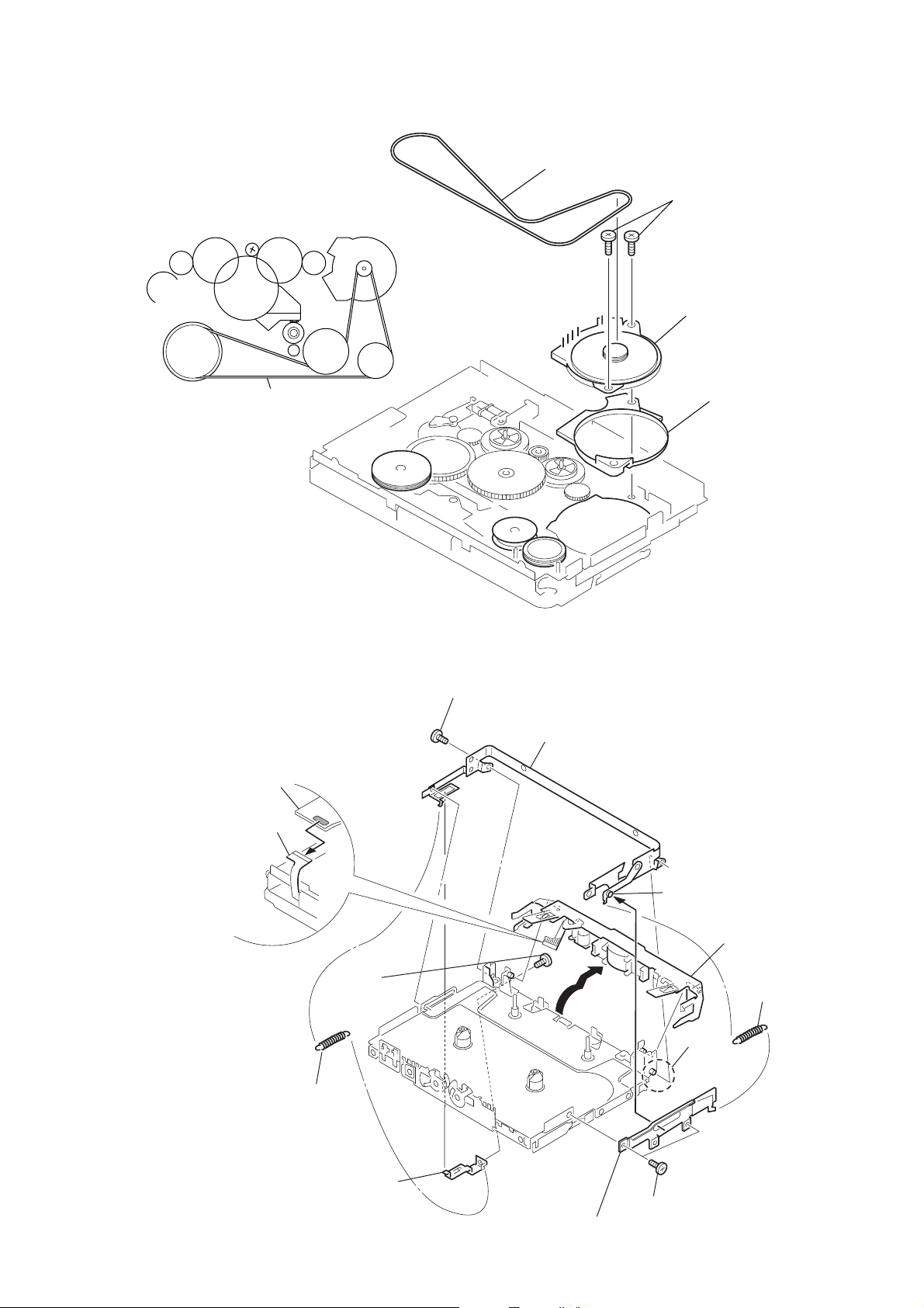
3-5. BELT (F0), MOTOR (M601)
)
Ver 1.2 2003. 11
1 Belt (F0)
2 Two screws (M1.4)
4 Motor (M601)
Belt (F0)
3-6. HOLDER (FA) ASSY
qa Remove soldering
from Head flexible board.
qs Head flexible
board
3 Retainer (F1), moto
8 Screw (M1.4)
0 Bracket (CASSETTE) assy
2 Screw
(M1.4)
1 Spring, tension
3 Hook, spring
6 Shaft
qd Remove the holder (FA
assy in the direction
of the arrow.
4 Spring, tension
9 Shaft
5 Two screws (M1.4)
7 Lever (B) assy, lock
— 7 —
 Loading...