

Sony WM-EX190,WM-EX192 Service Manual
WM-EX190/EX192
US Model
Canadian Model
WM-EX190
AEP Model
E Model
Chinese Model
WM-EX190/192
SERVICE MANUAL
CASSETTE PLAYER
MICROFILM
SPECIFICATIONS
Model Name Using Similar Mechanism NEW
Tape Transport Mechanism Type MT-WMEX192-114
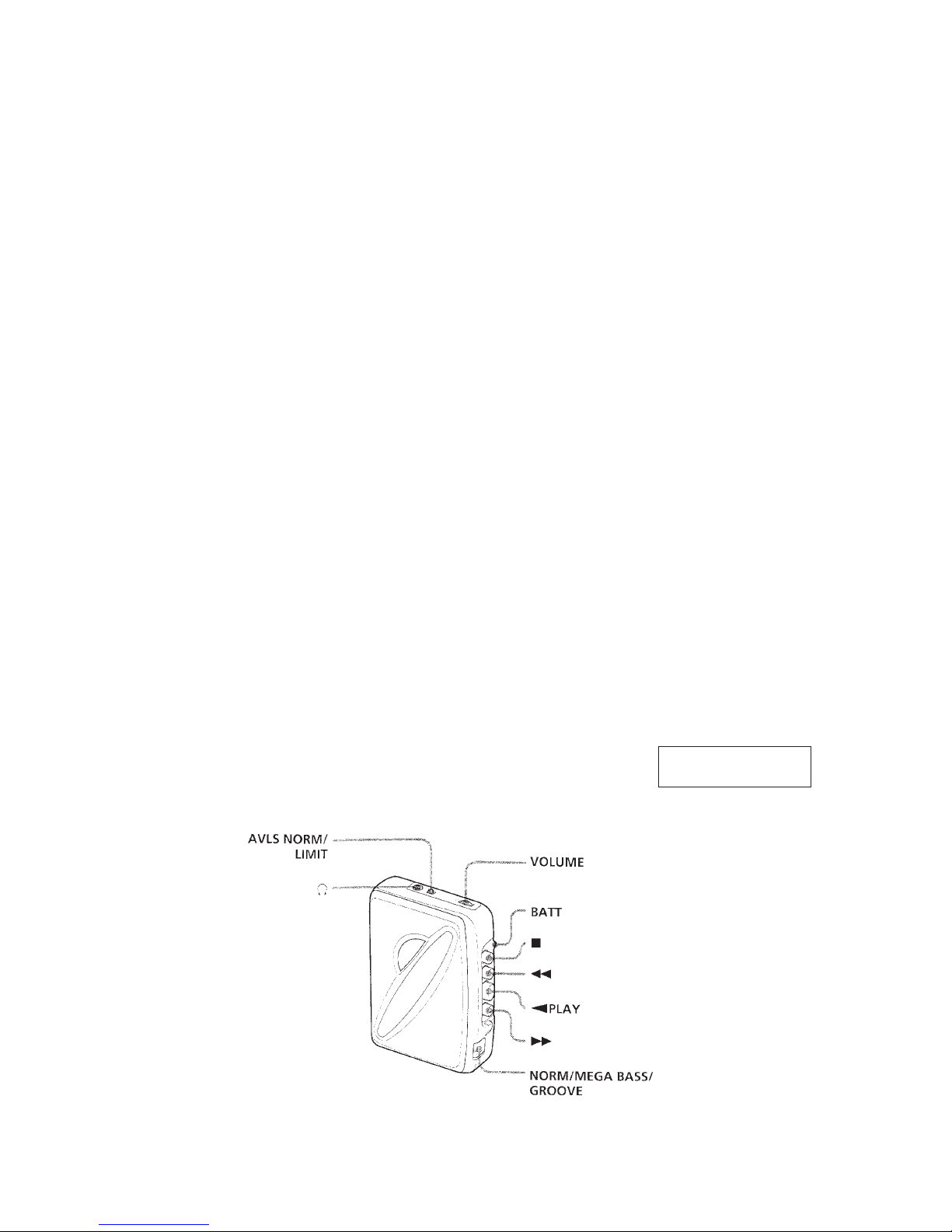
•Power requirements
3V DC batteries R6 (AA) × 2
•Dimensions
82 × 111.5 × 34.5 mm
(w / h/ d) incl. projecting parts and controls
•Mass
Approx. 115 g / Approx. 190 g incl.
batteries and a cassette
•Supplied accessories
Stereo headphones or Stereo earphones (1) / Belt clip (1)
Design and specifications are subject to change without notice.
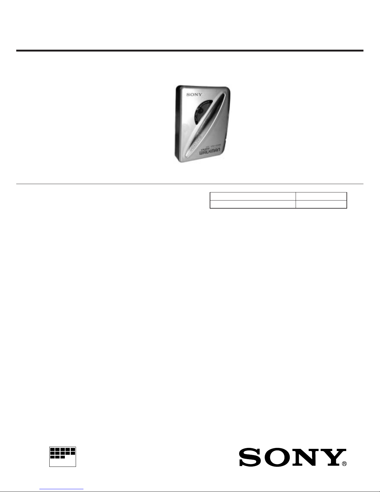
Photo : WM-EX192
Ver 1.0 2000. 01
— 2 —
TABLE OF CONTENTS
Flexible Circuit Board Repairing
• Keep the temperature of the soldering iron aroud 270˚ C during
repairing.
• Do not touch the soldering iron on the same conductor of the
circuit board (within 3 times).
• Be careful not to apply force on the conductor when soldering
or unsoldering.
Notes on chip component replacement
• Never reuse a disconnected chip component.
• Notice that the minus side of a tantalum capacitor may be
damaged by heat.
SECTION 1
GENERAL
1. GENERAL ······································································ 2
2. DISASSEMBLY
2-1. Cabinet (REAR) ································································· 3
2-2. Main Board·········································································4
2-3. Lid, Cassette ······································································· 4
2-4. Mechanism Deck ································································ 5
2-5. “BELT” “MOTOR” “PINCH LEVER” “HEAD,
MAGNETIC” ····································································· 5
3. MECHANICAL ADJUSTMENT ······························ 6
4. ELECTRICAL ADJUSTMENT ································ 6
5. DIAGRAMS
5-1. Block Diagram ··································································· 7
5-2. Printed Wiring Board·························································· 9
5-3. Schematic Diagram ··························································11
5-4. IC Block Diagram ···························································· 13
6. EXPLODED VIEWS
6-1. Cabinet Section································································· 14
6-2. Main Board Section·························································· 15
6-3. Mechanism Section-1 ······················································· 16
6-4. Mechanism Section-2 ······················································· 17
7. ELECTRICAL PARTS LIST ···································18
This section is extracted
from instruction manual.
— 3 —
SECTION 2
DISASSEMBLY
Note : Follow the disassembly procedure in the numerical order given.
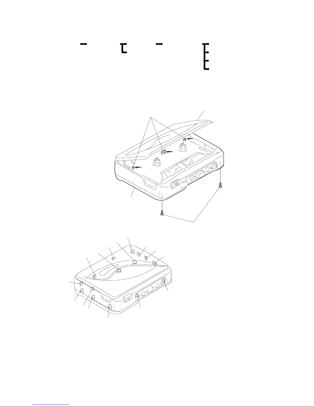
2-1. CABINET (REAR)
• This set can be disassembled in the order shown below.
Cabinet (rear) Set Main board
Lid assy, cassette
Mechanism deck Belt
Motor
Pinch lever (N) assy
Head, magnetic
A
1
Two screws (B1.7 × 9
)
2
Open the lid, cassette
3
Cabinet (rear)
(There 16 claws of
A
to P are caught.)
B
K
M
L
C
N
O
P
D
E
F
G
H
I
J
— 4 —
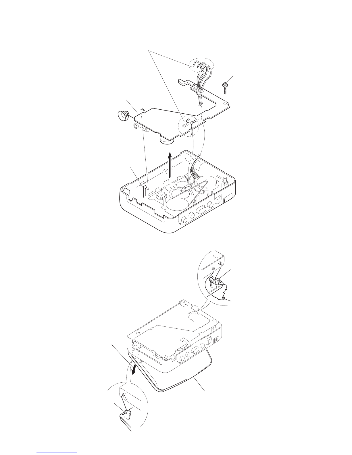
2-2. MAIN BOARD
2-3. LID ASSY, CASSETTE
1
Remove the solders.
2
Screw (M1.4
)
Claw
3
MAIN board
(There is a claw.)
2
Spring (torsion)
5
Lid assy, cassette
1
Open the lid, cassette
3
Release the catc
h
4
Release
the catch
— 5 —
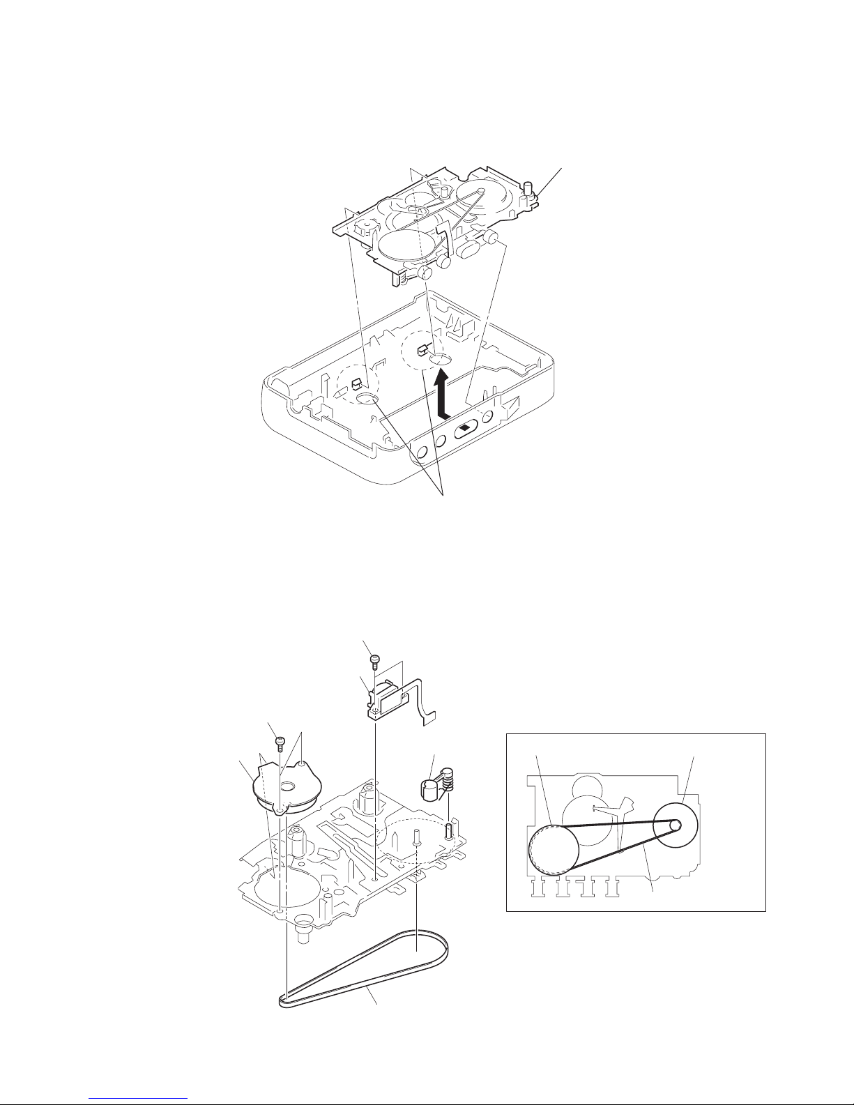
2-4. MECHANISM DECK
2-5. BELT, MOTOR, PINCH LEVER (N) ASSY, “HEAD, MAGNETIC”
1
Remove the mechanism dec
k
in the direction of the arrow.
(There two claws.)
Two claws
2
Two screws (M1.4)
5
Two screws (M1.4)
3
Motor (reel/capstan)
6
Head,magnetic (playback)
4
Pnch lever (N) assy
1
Belt
Motor (reel/capstan)
Wheel assy (sp), capstan
Belt threading
Belt
 Loading...