

Page 1

OPERATING INSTRUCTIONS
Please read this operating manual thoroughly
before operating this high quality electronic
unit, so that you can obtain the maximum en
joyment from it.
This manual should be retained for future ref
erence and used to answer your operational
questions as they arise.
PROFESSIONAL
UJALKiTlRn
WALKMAN is a trademark of Sony Corporation
11983 by Sony Corporation
Page 2

OWNER’S RECORD
TABLE OF CONTENTS
The model number is located at the rear and •
the serial number is located in the battery
compartment.
Record the serial number in the space pro
vided below.
Refer to these numbers whenever you call
upon your Sony dealer regarding this
product.
Model No. WM-D6C
Serial No
______________________
INFORMATION
This equipment has been tested and found to
compiy with the iimits for a Class B digital
device, pursuant to Part 15 of the FCC Rules.
These limits are designed to provide reasonable
protection against harmful interference in a
residential installation. This equipment
generates, uses, and can radiate radio frequency
energy and, if not-installed and used in
accordance with the instructions, may cause
harmful interference to radio communications.
However, there is no guarantee that interference
will not occur in a particular installation. If this
equipment does cause harmful interference to
radio or television reception, which can be
determined by turning the equipment off and on,
the user is encouraged to try to correct the
interference by one or more of the following
measures;
Features ......................................................... 3
Precautions....................................................
Battery insertion.............................................. 4
Cassette insertion
Playback
Recording
Other power sources
Functions to make recording/piayback
How to use the carrying case and
Maintenance
Specifications.................................................12
Parts identification
........................................................
easy
..........................................................
shouider strap............................................11
..........................................
......................................................
.....................................
.................................................
.........................................
10
12
14
3
5
6
8
9
• Reorient or relocate the receiving antenna.
• Increase the separation between the
equipment and receiver.
• Connect the equipment into an outlet on a
circuit different from that to which the receiver
is connected.
• Consult the dealer or an experienced radio/TV
technician for help.
Warning
You are cautioned that any changes or
modifications not expressly approved in this
manual could void your authority to operate this
equipment.
Page 3

FEATURES
PRECAUTIONS
• Quartz lock capstan servo system assures
accurate and stable tape speed.
• In addition to the conventional B-type
Dolby * * NR system, the WM-D6C employs the
C-type Dolby NR system which reduces tape
noise twice as effectively as the B-type
system.
• Speed control adjusts the tape speed
accurately (approx. ±4%) in the playback
mode.
0 DC-DC converter boosts the low voltage of
DC 6V and maintains sufficient power,
e Amorphous head for recording/playback
provides a wider dynamic range and a more
extended frequency response.
• Tape selector for optimum recording with
standard tapes as well as high-performance
tapes.
• Microphone attenuator eliminates the dis
tortion which may be caused by high-level
input signal.
• MIC (PLUG IN POWER) jack can supply
power to an ECM-909Aelectret condenser
stereo microphone (optional).
e Three different power sources: batteries,
house current, and 12 V car battery,
e 5-LED peak/battery indicator shows both
the peak level and the battery strength,
e Stereo minijacks can be used for connect
ing to audio components.
• Dolby noise reduction manufactured under license from Dolby
Laboratories Licensing Corporation.
“DOLBY” and the double-D symbol ÜD are trademarks of Dolby
Laboratories Licensing Corporation.
e Operate the set only on 6V dc.
• Do not leave the set near heat sources
such as radiators or airducts, or in a place
subject to direct sunlight, excessive dust,
moisture, rain, or mechanical shock.
• Should any liquid or solid object fall into
the set, remove the batteries and disconnect
the ac power adaptor or the car battery cord,
and have the set checked by qualified person
nel before operating it any further.
-On headphones------------------
Road safety
Do not use headphones while driving,
cycling, or operating any motorized vehicle. It
may create a traffic hazard and is illegal in
some areas. It can also be potentially
dangerous to play your headsets at high
volume while walking, especially at
pedestrian crossings.
You should exercise extreme caution or
discontinue use in potentilally hazardous
situations.
Preventing hearing damage
Do not use headphones at high volume.
Hearing experts advise against continuous,
loud and extended play. If you experience a
ringing in your ears, reduce volume or
discontinue use.
Caring for others
Keep the volume at a moderate level. This
will allow you to hear outside sounds and to
be considerate to the people around you.
• The record button cannot be depressed in
the following cases. Never depress the but
ton forcibly.
• No cassette in the cassette compartment.
• The cassette inserted has had the tabs
removed.
If you have any question or problem concern
ing your set that is not covered in this man
ual, please consult the nearest Sony Service
Station authorized to service tape recorders.
Page 4
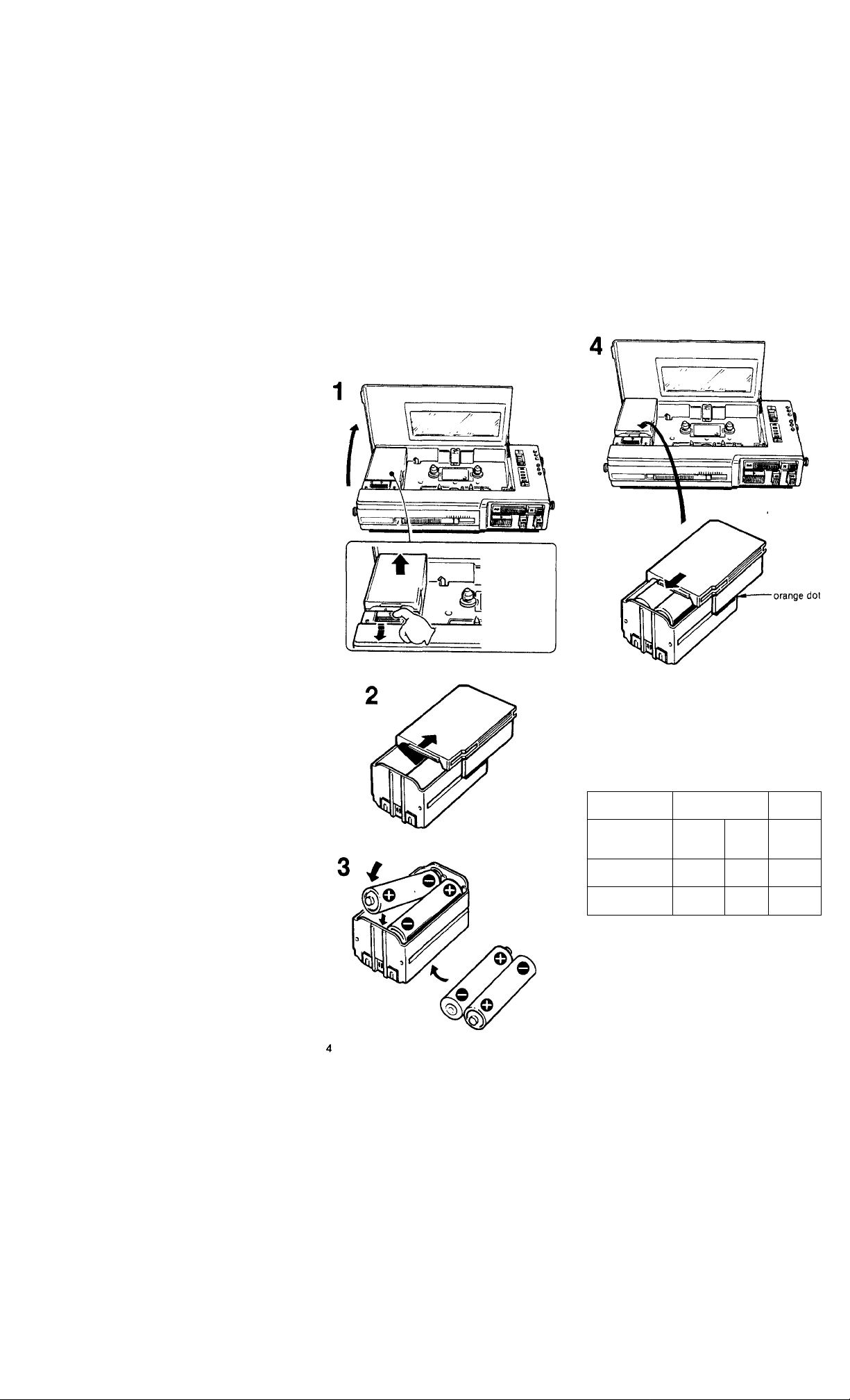
BATTERY INSERTION
Insert four batteries, size AA (lEC designation
R6), with correct polarity, referring to the
illustration below.
Note: When the set is not to be used for a
long period of time or is to be operated exten
sively on other power sources, remove the
batteries to avoid set damage caused by bat
tery leakage and corrosion.
Battery life
continuous
playback
TYPE 1, IV
6
N^type of cassette
batteries
Sony AM3 (N)
alkaline batteries
Sony SUM-3 (NS)
batteries
' (hours)
continuous recording
TYPE IV TYPEI
4 5
2 2.5 3
To check the battery condition, press any of
the function buttons and set the peak/battery
indication seiector to ВАТТ. The bottom
most LED wiil giow showing battery condi
tion. if the indicator glows faintly replace all
batteries at once.
• The life of other type batteries or batteries
of other manufacturers may be different.
Page 5

CASSETTE INSERTION
Take up any slack in the tape with a thick
pencil, and insert a cassette with the desired
side up. Avoid touching the tape surface.
I
Page 6

PLAYBACK
CONNECTION
For playback through the headphones
OPERATION
to LINE OUT
For playback through speakers
^ R f f L
red plug: to
right channel
supplied connecting cord
I I
to TAPE or
AUX
white plug: to
left channel
1 Insert a cassette.
2 Set the TAPE selector to the appropriate
position.
3 For Dolby B-type NR processed tape, set
the DOLBY NR selector to B-TYPE.
For Dolby C-type NR processed tape, set it
to C-TYPE.
For non-Dolby NR processed tape, set it to
OFF.
4 Depress the ► PLAY button. Playback will
begin.
5 Adjust the volume of the headphones with
the HEADPHONE VOLUME control.
Adjust the volume of the speakers with
the volume control of the amplifier.
To stop the tape during playback, press the
button.
To rewind the tape, press the REVIEW
button.
To advance the tape rapidly, press the
CUE button.
Page 7

SPEED TUNE SELECTOR AND CONTROL
The playback speed can be adjusted to tune
the pitch of a tape, recorded on another tape
recorder. Set the SPEED TUNE selector to ON
and turn the SPEED TUNE coTrtrol to F (fast)
or S (slow). For normal tape speed, set it fo
OFF.
When the • RECORD button is pressed, this
selector is automatically set to the OFF posi
tion.
TO DUPLICATE ONTO ANOTHER TAPE
RECORDER
Use the supplied connecting cord, or an optionai
RK-G129HG or RK-G136HG connecting cord.
another tape
WM-D6C
RK-G129HG
LINE OUT
RK-G136HG
recorder
LINE IN
LINE IN
Page 8

RECORDING
CONNECTION
Notes
• To connect a stereo microphone with two
L and R miniplugs or two microphones with a
miniplug, use an optional PC-239S plug adaptor.
• This set suppiies power to the ECM-909A
from the MIC jack. When you use the ECM909A, remove the battery inside the ECM-909A.
Page 9

OPERATION
OTHER POWER SOURCES
HOUSE CURRENT
Use the Sony AC-D4HG AC power adaptor
(optional).
First connect the adapTbr to DC IN 6 V jack,
and then to a wall outlet.
Before connecting, be sure to read the in
struction manual for the adaptor.
12 V CAR BATTERY
Use the Sony DCC-120A car battery cord
(optional), and connect the DC IN 6V jack on the
set to the cigarette lighter socket of a car. Set the
voltage selector of the DCC-120A to 6V. For
further details, refer to the instruction manual of
the car battery cord.
1 Insert a cassette.
2 Set the TAPE selector to the appropriate
position.
3 For recording with Dolby B-type NR pro
cess, set the DOLBY NR selector to
B-TYPE. For recording with Doiby C-type
NR process, set it to C-TYPE. For record
ing without Dolby NR process, set it to
OFF.
4 Adjust the recording level following steps
4 to 7. Set the peak/battery indication
selector to PEAK.
5 Depress the ll button.
6 Depress the • RECORD button.
7 Adjust the REC LEVEL control, referring
to the level meter.
8 Press the II button again to release the
pause mode. Recording will begin.
To listen to the sound being recorded,
connect the headphones.
To stop recording, press the button.
Recording levels for metal, CrOj and normal
tapes are different. When recording with
metal tapes, the level meter should peak at
about +6dB. For CrOz and normal tapes, the
peak level should be about -i-3dB. The
peak/battery indicator will show the highest
peak at the time for either the left or right
channel, whichever is higher at that instant.
Notes
• When the AC power adaptor or the car battery
cord is connected to the DC IN 6V jack, the
internal batteies (if present) are automatically
disconnected.
• Use only the AC-D4HG AC power adaptor or
DCC-120A car battery cord. Do not use any
other AC power adaptor or car battery cord.
Page 10

FUNCTIONS TO MAKE
RECORDING/PLAYBACK
EASY
MIC ATT (attenuator) switch
The microphone attenuator-is useful for re
cording a large input signal on location (like
rock music) or recording with a microphone
very close to the source without overloading
the recorder amplifier. Normally set this
switch to the OdB position. Set if to the20dB
position to avoid overloading the amplifier of
the recorder, when you make a live recording
with high input signals.
The “20 dB” position attenuates the input
level by 20dB.
Cue and review function
During playback, you may skip-over unneces
sary portions of the tape by pressing the ►►
CUE button or repeat a certain portion of the
tape by pressing the REVIEW button.
(The sound is muted during this function.)
When the ►► CUE or REVIEW button is
released, the recorder will automatically re
turn to the playback mode.
II (pause) button
Depress the II button to stop the tape for a
moment in playback or recording mode. To re
start, press the button again to release it.
T0 stop the tape for an extended time, use the
button.
Automatic shut-off mechanism
In playback or recording mode, tape motion
stops at the end of the tape and the locked
buttons will return to the original position
automatically.
In fast forward or rewind mode, however, the
locked button will not be released automati
cally. Be sure to press the fiB button to re
lease it.
Instant edit function
During playback, simply depress the •
RECORD button, and the recorder will im
mediately change to the recording mode.
This function is convenient for correcting a
previously recorded portion.
Peak/battery indicaUif and indication selector
To observe the input level during recording or
recorded level during playback, set this selec
tor to PEAK.
The Indicator will show the input level or the
recorded level for either the left or right chan
nel, whichever is higher at that instant.
To check the battery condition, set the selec
tor to ВАТТ. The bottom-most LED will light
to show the battery condition. If the indicator
glows faintly, replace all batteries at once.
When the selector is set to OFF, no LED will
light up.
Tape counter for indexing the tape contents
Before recording, push the reset button to set
the counter to “000". Make a note of the fig
ures to help you locate later a desired pro
gram on the tape.
To prevent accidental erasure
Break out the small tabs on the rear of the
cassette. The • RECORD button cannot be
depressed if a cassette with its tabs broken
out is used. To reuse a cassette for recording
after the tabs have been removed, simply
cover the slots with a small piece of cello
phane or vinyl tape.
One touch review function
During recording, you can listen to the mate
rial just recorded with this function. While
recording, when the -♦< REVIEW button is
depressed, only the • RECORD button will
be released and the tape will be rewound. By
releasing the REVIEW button, the
recorder will go Into the playback mode.
10
To make a blank erasure
1 Insert a cassette.
2 Ensure that nothing is connected to the
LINE IN and MIC jacks.
3 Set the REC LEVEL control to minimum.
4 Depress the • RECORD button.
Page 11

HOW TO USE THE CARRYING
CASE AND SHOULDER STRAP
11
Page 12

MAINTENANCE
SPECIFICATIONS
CLEANING THE HEADS
Clean the heads after every 10 hours of use to
enjoy optimum hi-fi stereo sound: moisten a
cotton swab or a soft clotb with denatured
alcohol, and gently wipe the parts shown
below.
record/playback head
DEMAGNETIZING THE HEADS
Either prolonged use, or an accidental con
tact with a piece of magnetized steel (screw
driver, scissors, etc.) will magnetize the
heads causing an increase in tape noise. In
such an event,demagnetize the heads using
a commercially available head demagnetizer.
CLEANING THE CASING
Clean the casing with a soft cloth slightly
moistened with water or a mild detergent
solution. Do not use solvents such as alco
hol, benzine, or thinner as they may mar the
finish of the casing.
Recording system
4-track, 2-channel stereo
Wow and flutter
±0.14% (DIN)
0.04<)^WRMS (NAB)
Tape speed deviation
±0.3% (speed tuning OFF)
Speed tuner variations
Approx. ±4%
Frequency response
DOLBY NR OFF
• With TYPE IV cassette
40-15,000 Hz±3dB
• With TYPE II cassette
40-15,000 Hz±3dB
• With TYPE I cassette
40-15,000 Hz±3dB
S/N (NAB, at peak level)
DOLBY NR C
TYPE IV cassette
71 dB
TYPE II cassette
71 dB
TYPE I cassette
67 dB
DOLBY NR В
TYPE IV cassette
65 dB
TYPE II cassette
65 dB
TYPE I cassette
61 dB
DOLBY NR OFF
TYPE IV cassette
58 dB
TYPE II cassette
58 dB
TYPE 1 cassette
54 dB
Total harmonic distorsion
0.9% with TYPE IV cassette
Inputs MIC (PLUG IN POWER)
(stereo minijack) x 1
0.25 mV with low impedance
microphone
LINE IN (stereo minijack) x 1
77.5 mV (47 kilohms)
12
Page 13

Outputs LINE OUT (stereo minijack)
x1
output level 0.25 V (less than
4.7 kilohms)
Headphones (stereo
minijack) xi
load impedance 8-300 ohms
Power output Headphones
30mW + 30mW (at io%
harmonic distortion)
load impedance 32 ohms
Battery life See page 4.
Power requirements
6V dc, four batteries, size
AA (lEC designation R6)
External power input jack
(required power 6V dc)
accepts Sony AC-D4HG AC
power adaptor (optional) for
use on 120 V ac 60 Hz or
Sony DCC-120A car battery
cord (optional) for use on
12 V car battery
Dimensions 181 x40 x95 mm (w/h/d)
(7‘/<Ives'SV4 inches)
including projecting parts
Weight Approx. 640g (1 lb 7oz)
including batteries
Supplied accessories
Stereo headphones (1)
Connecting cord (1)
Carrying case and shoulder
strap (1 set)
Design and specifications subject to change
without notice.
OPTIONAL ACCESSORIES
AC power adaptor AC-D4HG
Car battery cord DCC-120A
Electret condenser stereo microphone
(with stero miniplug) ECM(^09A
Stereo headphones
MDR-94, MDR-CD550
Connecting cord
RK-G129HG (stereo minipiug to two phono
plugs)
RK-G136HG (stereo miniplug to stero
mini-plug)
Plug adaptor PC-239S (stereo miniplug to two
minijacks)
Continued trouble-free operation of any tape
recorder is dependent on the quality of the
cassettes used in conjunction with it. The
use of Sony cassettes is recommended for
high quality recording and trouble-free opera
tion.
Your dealer may not handle some of the
above listed optional accessories. Please ask
the dealer for detailed information about the
optional accessories available in your
country.
13
Page 14

PARTS IDENTIFICATION
O Peak/battery indicator and indication
selector
0 Tape counter and reset button
O DOLBY NR selector
O TAPE selector
0 REC LEVEL (recording level) control
O • RECORD button
O MIC ATT (microphone attenuator) switch
O MIC (PLUG IN POWER) jack (stereo mini-
jack)
O HEADPHONES jack
14
0 0 0
® II (pause) button
0 (fast forward) CUE button
® (rewind) REVIEW button
© ► PLAY (playback) button
© £■ (eject/stop) button
© HEADPHONE VOLUME control
© LINE IN jack
© LINE OUT jack
® SPEED TUNE selector and control
© DC IN 6 V jack
 Loading...