

Sony WEGA KV-36FV1, WEGA KV-32FV1 Operating Instructions Manual
3-862-737-21 (1)
Operating Instructions
KV-32FV1 KV-36FV1
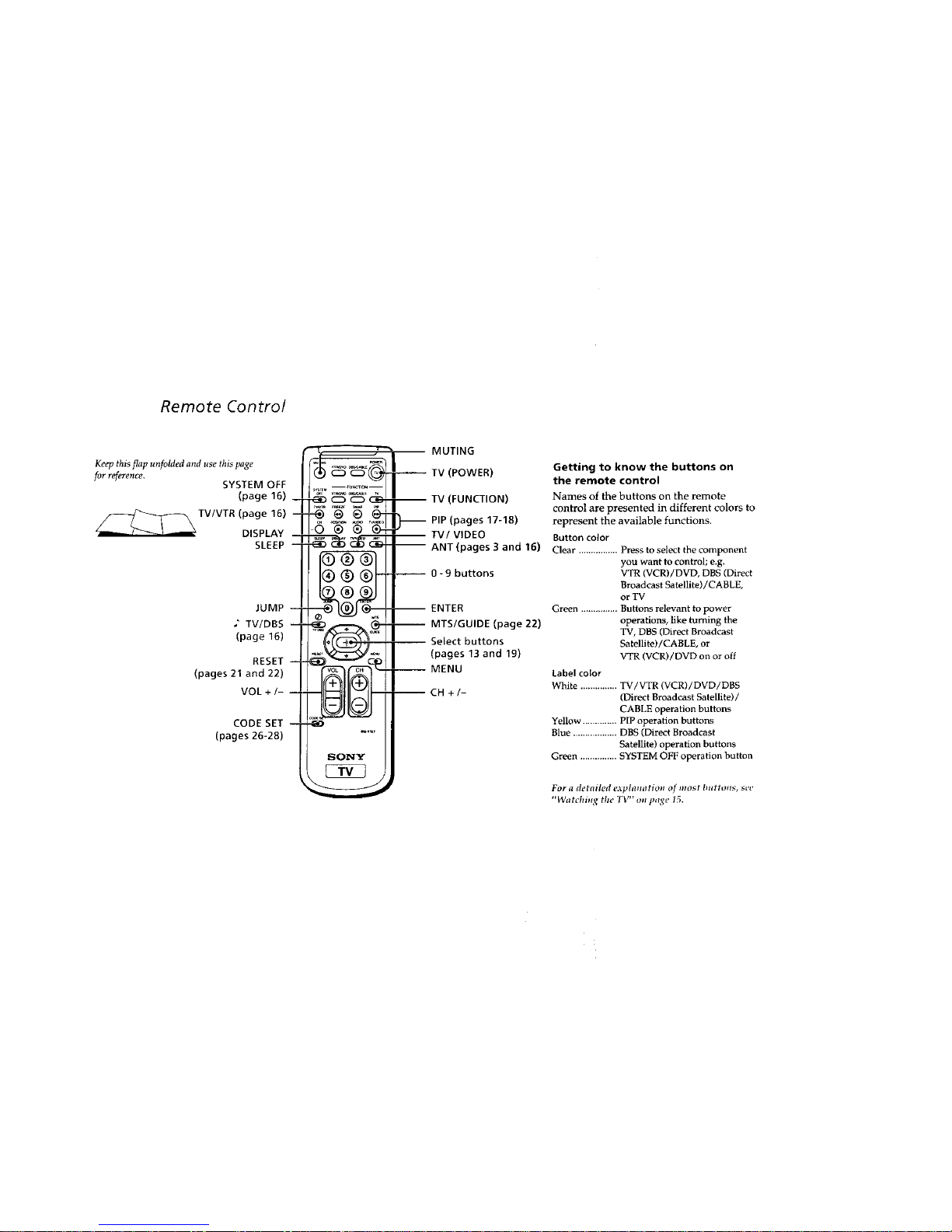
Remote Control
Keep this flap unfolded and use this page
forreference,
SYSTEM OFF
(page 16)
TV/VTR (page 16)
DISPLAY --
SLEEP --
JUMP --
.' TV/DBS --
(page 16)
RESET --
(pages 21 and 22)
VOL +/- --
CODE SET
(pages 26-28)
MUTING
(POWER)
SONY
-- ENTER
-- MTS/GUIDE (page 22)
Select buttons
(pages 13 and 19)
-- MENU
CH +/-
Getting to know the buttons on
the remote control
Names of the buttons on the remote
control are presented in different colors to
represent the available functions.
Button color
Clear ................ Press to select the component
you want to control; e.g.
VTR (VCR)/DVD, DBS (Direct
Broadcast Satellite)/CABLE,
or TV
Green ............... Buttons relevant to power
operations, like turning the
TV, DBS (Direct Broadcast
Satellite)/CABLE, or
VTR (VCR)/DVD on or off
Label color
White ............... TV/VTR (VCR)/DVD/DBS
(Direct Broadcast Satellite) /
CABLE operation buttons
Yellow .............. PIP operation buttons
Blue .................. DBS (Direct Broadcast
Satellite) operation buttons
Green ............... SYSTEM OFF operation button
For a detailed eAphlmltion lff most buttons, see
"Watchi_ tile TV" _s page 15.
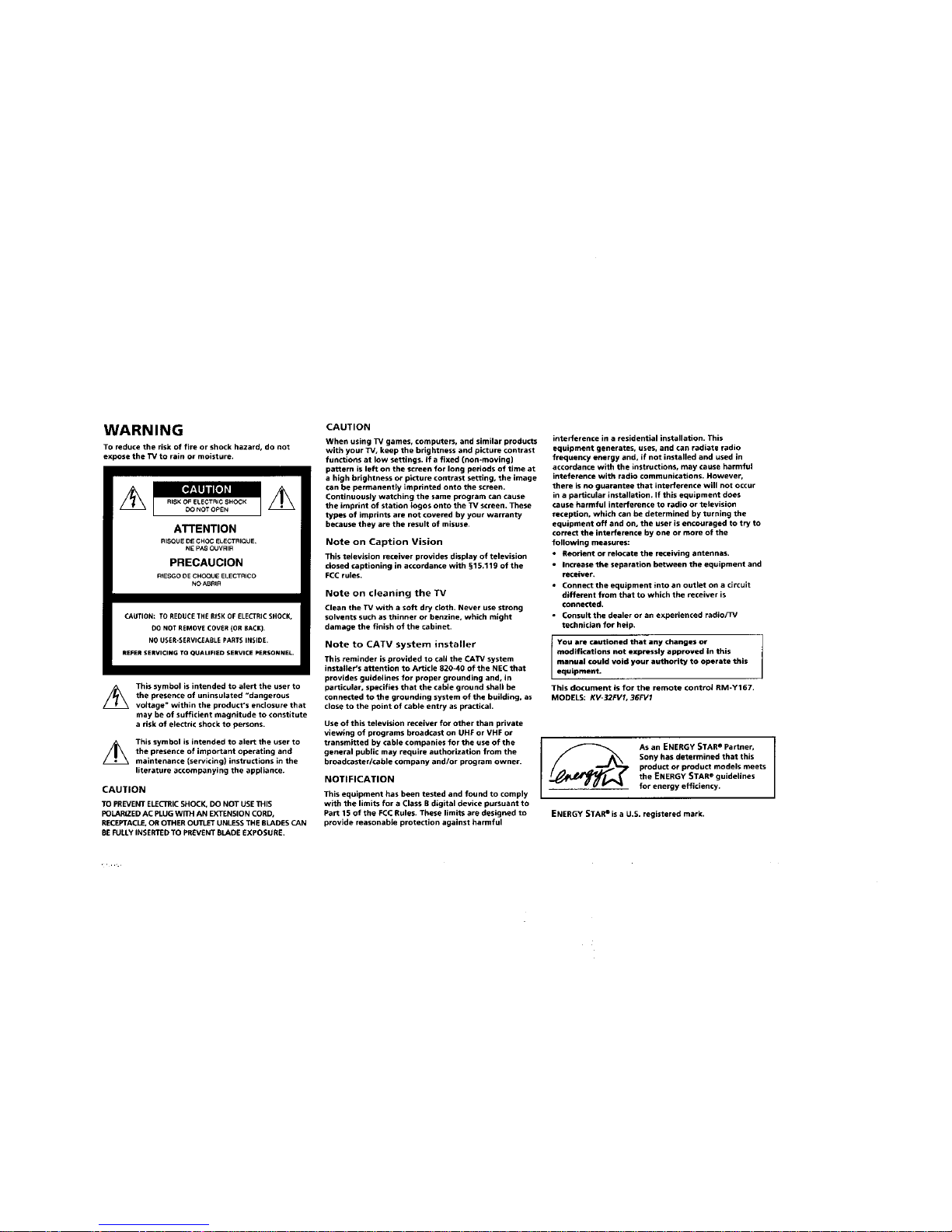
WARNING
To reduce the risk of fire or shock hazard, do not
expose the TV to rain or moisture.
ATTENTION
RISOUE DE CHOC ELECTRIQUE
NE PAS OUVRIH
PRECAUClON
RIESGO DE CHOQUE ELECTRiCO
NO ABRIR
/h
CAUTION: TO REDUCETHE RiSK OF ELECTRIC SHOCK,
O0 NOT REMOVE COVER (OR BACK).
NO USER-SERVICEABLE PARTSINSIDE.
REFERSERVICING TO OUALIFIED SERVICE PERSONNEL.
This symbol is intended to alert the user to
the presence of uninsulated "dangerous
voltage" within the product's enclosure that
may be of sufficient magnitude to constitute
a risk of electric shock to persons.
This symbol is intended to alert the user to
the presence of important operating and
maintenance (servicing) instructions in the
literature accompanying the appliance.
CAUTION
TO PREVENT ELECTRIC SHOCK. DO NOT USE THIS
POLARIZED AC PLUG WITH AN EXTENSION CORD,
RECEPTACLE, OR OTHER O_ UNLESS THE BLADES CAN
BE FULLY INSERTED TO PREVENT BLADE EXPOSURE,
CAUTION
When using W games, computers, and similar products
with your TV, keep the brightness and picture contrast
functions at low settings. If a fixed (non-moving)
pattern is left on the screen for long periods of time at
a high brightness or picture contrast setting, the image
can be permanently imprinted onto the screen.
Continuously watching the same program can cause
the imprint of station Iogos onto the TV screen. These
types of imprints are not covered by your warranty
because they are the result of misuse.
Note on Caption Vision
This television receiver provides display of television
dosed captioning in accordance with §15.119 of the
FCC rules.
Note on cleaning the TV
Clean the TV with a soft dry cloth. Never use strong
solvents such as thinner or benzine, which might
damage the finish of the cabinet.
Note to CATV system installer
This reminder is provided to call the CATV system
instager's attention to Article 820-40 of the NEC that
provides guidelines for proper grounding and, in
particular, specifies that the cable ground shall be
connected to the grounding system of the building, as
close to the point of cable entry aspractical.
Use of this television receiver for other than private
viewing of programs broadcast on UHF or VHF or
transmitted by cable companies for the use of the
general public may require authorization from the
broadcaster/cable company and/or program owner.
NOTIFICATION
This equipment has been tested and found to comply
with the limits for a Class B digital device pursuant to
Part 1S of the FCC Rules. These limits are designed to
provide reasonable protection against harmful
interference in a residential installation. This
equipment generates, uses, and can radiate radio
frequency energy and, if not installed and used in
accordance with the instructions, may cause harmful
inteference with radio communications. However.
there is no guarantee that interference will not occur
in a particular installation. If this equipment does
cause harmful interference to radio or television
reception, which can be determined by turning the
equipment off and on, the user is encouraged to try to
correct the interference by one or more of the
following measures:
• Reorient or relocate the receiving antennas.
• Increase the separation between the equipment and
receiver.
• ConnecttheequipmentintoanoutletonacJrcuit
different from that to which the receiver is
connected.
• Consult the dealer or an experienced radio/TV
technician for hetp.
I YOU are cautioned that any changes or
modifications not expressly approved in this
manual could void your authority to operate this
equipment.
This document is for the remote controt RM-Y167.
MODELS: KV-32FVI, 36FVI
As an ENERGY STARe Partner,
Sony has determined that this
product or product models meets
the ENERGY STARe guidelines
for energy efficiency.
ENERGY STARe isa U.S. registered mark.
ii Welcome!
rhank you for purchasing the Sony
Frinitron ®Color TV. Before reading, check
fie model number located on the front of this
manual or on the rear of your TV.
Pae features you willenjoy include:
A flat CRT, for optimal picture quality
Component video (Y, Ps, P_ inputs for the
highest quality DVD Player connection
Dual tuner PIP, which allows you to watch
two programs at once without first
connecting any additional equipment
The FAVORITE CHANNEL feature, which
allows you to preview each of your chosen
favorite channels in a small window
picture before you choose to tune to a
particular channel
• AfrontA/Vinput, foreasyconnectionof
your cameorder or game equipment
• Two S VIDEO inputs, for enhanced picture
quality
Precautions
Safety
• Operate the TV only with 120 V AC.
• The plug is designed, for safety purposes,
to fit in the wail outlet only one way. If
you are unable to insert the plug fully into
the outlet, contact your dealer.
• If any liquid or solid object should fall
inside the cabinet, unplug the TV
immediately and have it checked by
qualified personnel before operating it
further.
• If you will not be using the TV for several
days, disconnect power by pulling the
plug itself. Never pull on the cord.
For details concerning safety precautions, see the
supplied leaflet "IMPORTANT SAFEGUARDS".
Installing
• To prevent internal heat build-up, do not
block the ventilation openings.
• Do not install the TV in a hot or humid
place, or in a place subject to excessive
dust or mechanical vibration.
• The AC power cord is attached to the rear
of the TV with hooks. Do not attempt to
remove the cord from these hooks. Doing
so could cause damage to the TV.
Using This Manual
This manual is divided into five major
sections. We recommend that you carefully
review the contents of each section in the
order presented to ensure that you fully
understand the operation of your new TV.
I Connecting and Installing the TV
This section guides you through your
initial set up. It shows how to connect to
your antenna or cable, and connect any
accessories or components.
2 BasicSet Up
This section teaches you the basic skills
needed to operate your new TV. It shows
you how to operate special functions of the
remote control.
Using your New TV
Thissectionshows you how tobeginusing
your new TV, Itshows how tousetheEasy
SetUp Guide feature,and how touseyour
remotecontrol.
4 UsingyourMenus
This section teaches you how to access
on-screen menus and adjust your TV's
settings.
5 Troubleshooting
This section helps you to correct problems
you may encounter with your TV.
Instructions in this manual are written for the
remote control. Similar controls may befound on
the TV console.
Connecting and Installing the TV
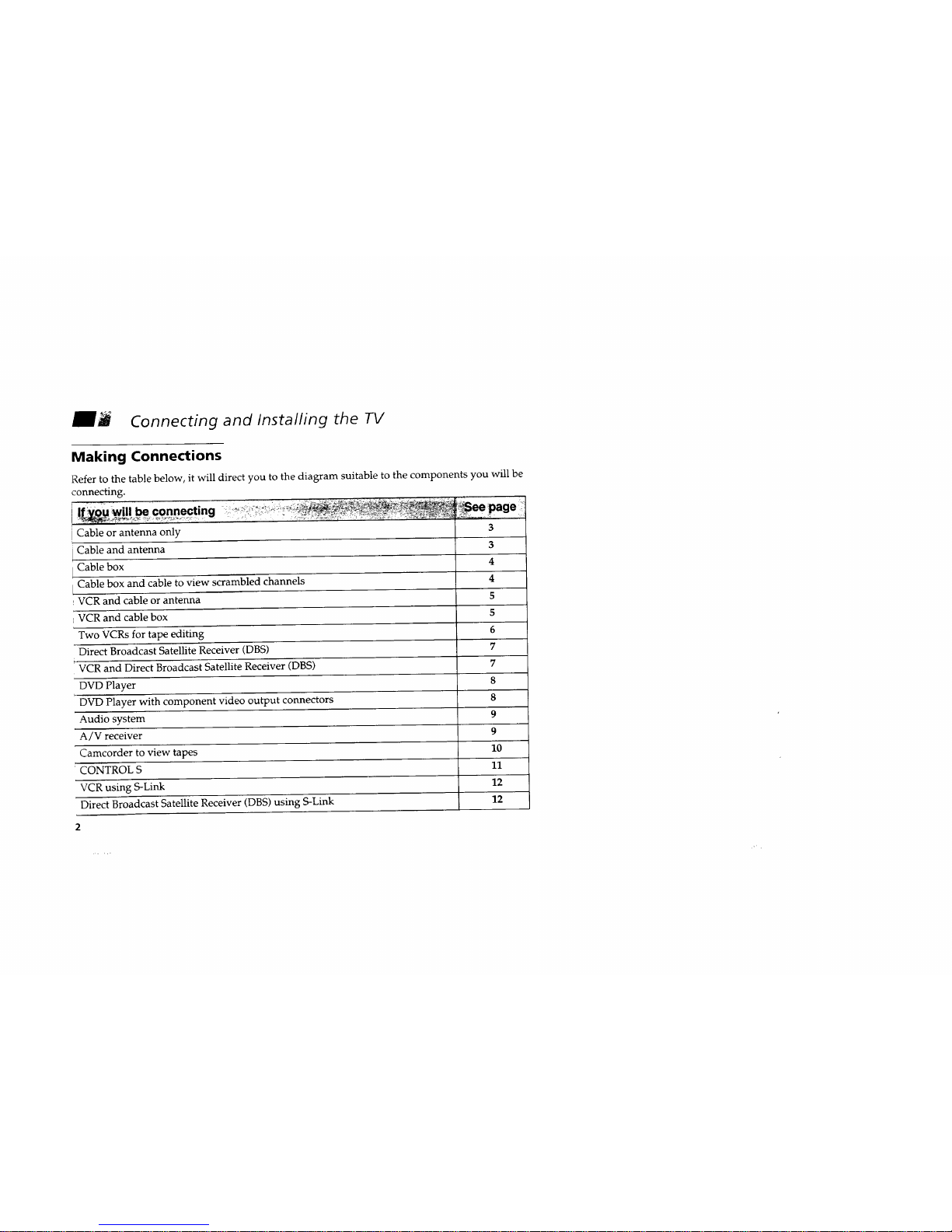
Making Connections
Refer to the table below, it will direct you to the diagram suitable to the components you will be
connecting.
Ifiw-uw_ll be connecting ....... _"............................ " "
Cable or antenna only 3
Cable and antenna 3
Cable box 4
Cable box and cable to view scrambled channels 4
VCR and cable or antenna 5
VCR and cable box 5
Two VCRs for tape editing 6
Direct Broadcast Satellite Receiver (DBS) 7
VCR and Direct Broadcast Satellite Receiver (DBS) 7
DVD Player 8
DvD Player with component video output connectors 8
Audio system 9
A/V receiver 9
Camcorder to view tapes 10
' CONTROL S 11
VCR using S-Link 12
Direct Broadcast Satellite Receiver (DBS) using S-Link 12
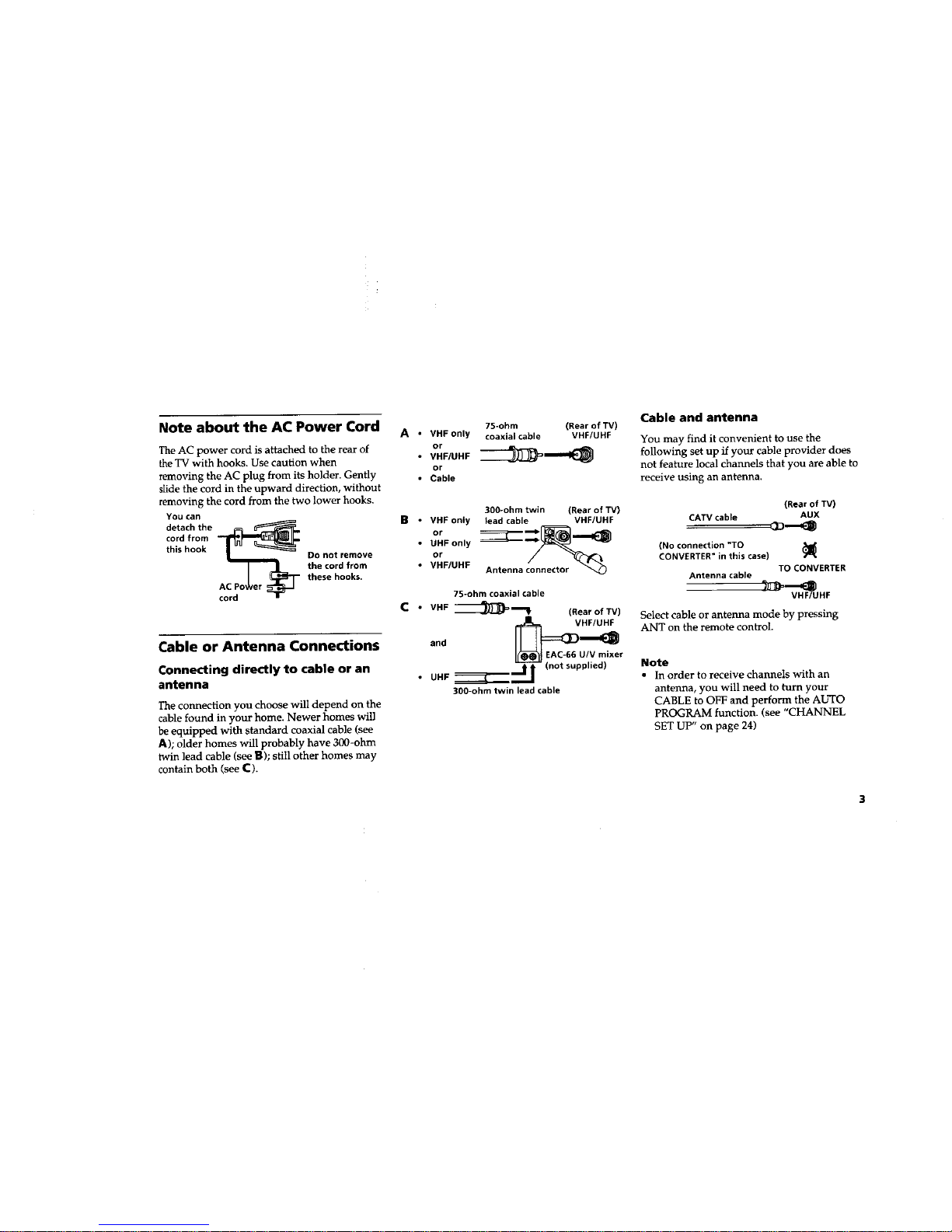
Note about the AC Power Cord
The AC power cord is attached to the rear of
the TV with hooks. Use caution when
removing the AC plug from its holder. Gently
slide the cord in the upward direction, without
removing the cord from the two lower hooks.
YOUcan
detach the
cord from
this hook
DO not remove
the cord from
these hooks.
AC P
cord
Cable or Antenna Connections
Connecting directly to cable or an
antenna
The connection you choose will depend on the
cable found in your home. Newer homes will
be equipped with standard coaxial cable (see
A); older homes will probably have 300-ohm
twin lead cable (see B); still other homes may
contain both (see C).
75-ohm (Rearof TV)
A • VHF only coaxiaicable VHF/UHF
or
• v.e,u.F
or
• Cable
300-ohm twin (Rear of TV)
B • VHF only lead cable VHF/UHF
or
• UHF only
or
• VHF/UHF Antenna connector _)
75-ohm coaxial cable
C • VHF----_)_
(Rear of TV)
and _)VHl_
EAC-66 U/V mixer
• UHF ===_1_ l"
(not supplied)
300-ohm twin lead cable
Cable and antenna
You may find it convenient to use the
following set up if your cable provider does
not feature local channels that you are able to
receive using an antenna.
(Rear of IV)
CATV cable AUX
(No connection "TO
CONVERTER" in this case)
TO CONVERTER
Antenna cable
VHF/UHF
Select cable or antenna mode by pressing
ANT on the remote control.
Note
• In order to receive channels with an
antenna, you will need to eum your
CABLE to OFF and perform the AUTO
PROGRAM function. (see "CHANNEL
SET UP" on page 24)
Connecting and Installing the TV (continued)
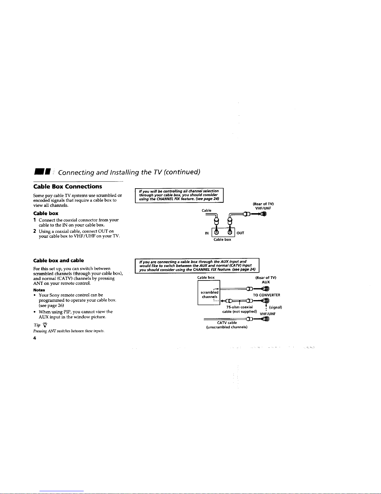
Cable Box Connections
Some pay cable TV systems use scrambled or
encoded signals that require a cable box to
view all channels.
Cable box
1 Connect the coaxial connector from your
cable to the IN on your cable box.
2 Using a coaxial cable, connect OUT on
your cable box to VHF/UHF on your TV.
I Ifyouwillbecontrollingallchannelselection
through your cable box, you should consider
using the CHANNEL FIX feature. (see page 24)
Cable
-3
IN
I
(Rear of TV)
VHF/UHF
[--_--] OUT
Cablebox
Cable box and cable
For this set up, you can switch between
scrambled channels (through your cable box),
and normal (CATV) channels by pressing
ANT on your remote control.
Notes
• Your Sony remote control can be
programmed to operate your cable box.
(see page 26)
• When using PIP, you cannot view the
AUX input in the window picture.
Tip"_ o
Pressing ANT switches between theseinputs.
4
I fyou are connecting a cable box through theAUXinputand
would like to switch between the AUX and normal (CATV) input
you should consider using the CHANNEL FIX feature. (see page 24)
Cable box (Rear of TV)
AUX
scrambled
channels TO CONVERTER
75-ohm coaxial ,_ (signal)
g
cable (not supplied) VHF/UHF
CATV cable
(unscrambled channels)
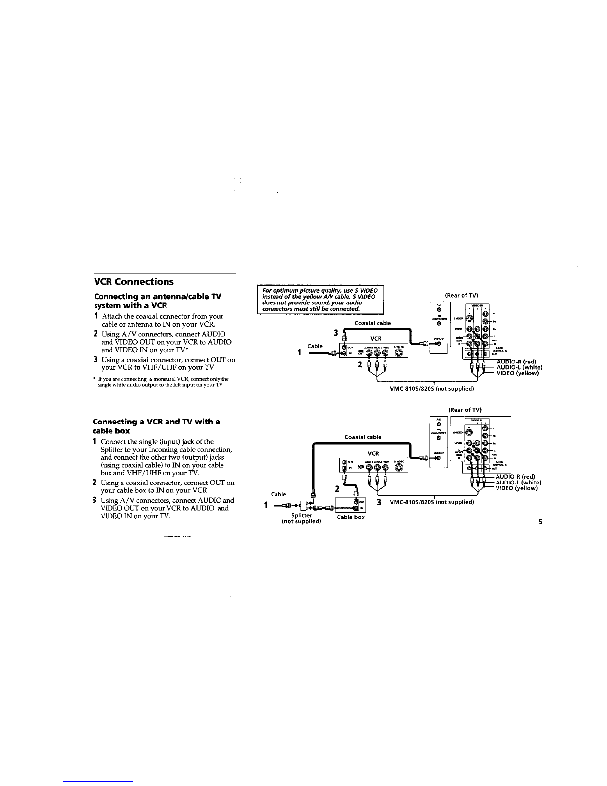
VCR Connections
Connecting an antenna/cable TV
system with a VCR
1 Attach the coaxial connector from your
cable or antenna to IN on your VCR.
2 Using A/V connectors, connect AUDIO
and VIDEO OUT on your VCR to AUDIO
and VIDEO IN on your TV*.
3 Using a coaxial connector, connect OUT on
your VCR to VHF/UHF on your TV.
• If you are connecting a monaural VCR, connect only the
single white audio output to the left input on your TV.
Connecting a VCR and TV with a
cable box
1 Connect the single (input) jack of the
Splitter to your incoming cable connection,
and connect the other two (output) jacks
(using coaxial cable) to IN on your cable
box and VHF/UHF on your TV.
Using a coaxial connector, connect OUT on
your cable box to IN on your VCR.
3 Using A/V connectors, connect AUDIO and
VIDEO OUT on your VCR to AUDIO and
VIDEO IN on your TV.
For optimum picture quality, use S VIDEO
instead of the yellow AN cable. S VIDEO
does not provide sound, your audio
connectors must still be connected.
Coaxial cable
3
Cable
1
(Rear of TV)
i
VMC-810S/820S (not supplied)
(Rear of "IV)
Coaxial cable
Cable 2L_ _
__.. 3 VMC-810S/820S (not supplied)
Splitter Cable box
(not supplied)
(red)
(white)
(yellow)
(red)
(white)
{yellow)
Connecting and Installing the TV (continued)
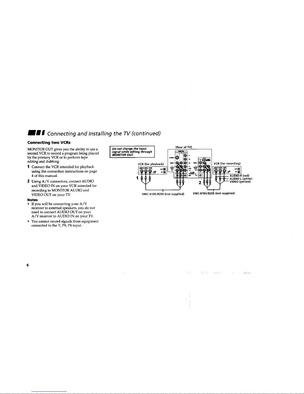
Connecting two VCRs
MONITOR OUT gives you the ability to use a
second VCR to record a program being played
by the primary VCR or to perform tape
editing and dubbing.
1 Connect the VCR intended for playback
using the connection instructions on page
4 of this manual.
2 Using A/V connectors, connect AUDIO
and VIDEO IN on your VCR intended for
recording to MONITOR AUDIO and
VIDEO OUT on your TV.
Notes
• If you will be connecting your A/V
receiver to external speakers, you do not
need to connect AUDIO OUT on your
A/V receiver to AUDIO IN on your TV.
• You cannot record signals from equipment
connected to the Y, PB, PR input.
Do not change the input
signal while editing through
MONITOR OUT.
(Rear of TV)
VCR (for playback)
I
VMC-810S/82OS (not supplied)
VCR (for recording)
_=_="_ _ AUDIO-R (red)
-- A A A _1 _ AUDIO-L (white)
2 _/_ _ VIDEO (yellow)
VMC-810S/820S (not supplied)
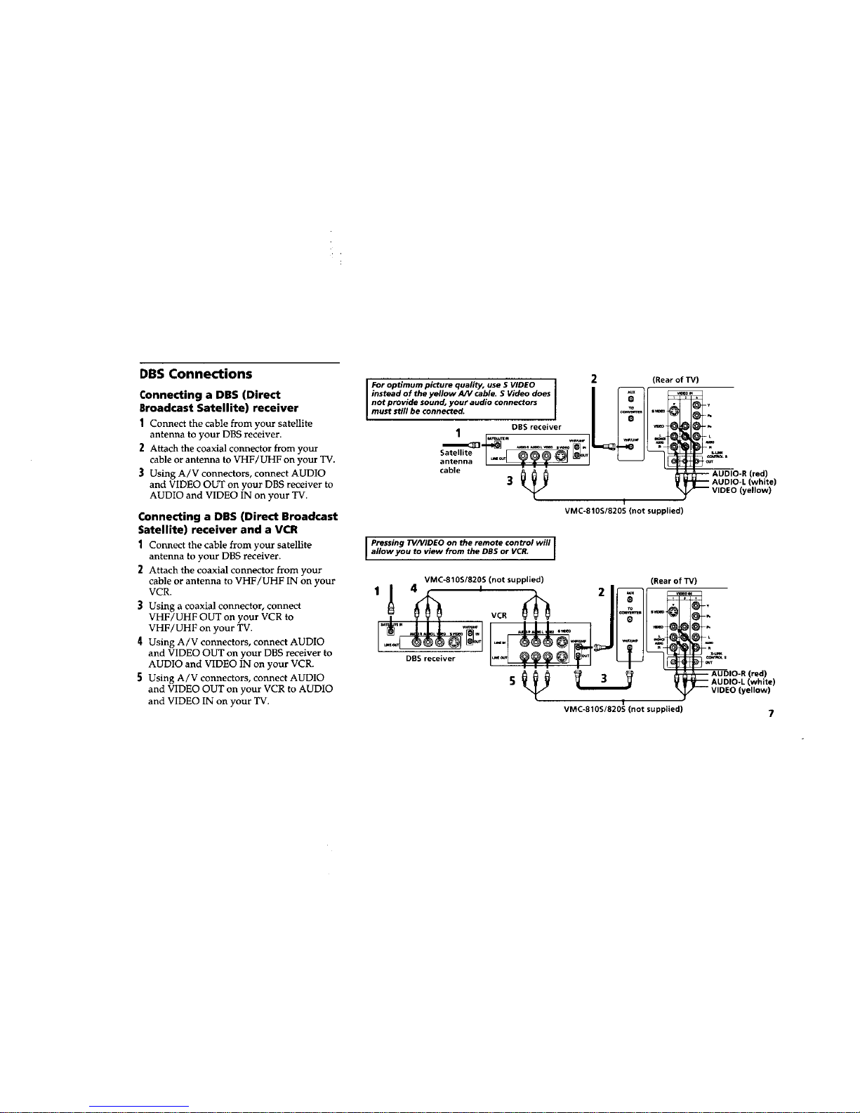
DBS Connections
Connecting a DBS (Direct
Broadcast Satellite) receiver
1 Connect the cable from your satellite
antenna to your DBS receiver.
2 Attach the coaxial connector from your
cable or antenna to VHF/UHF on your TV.
3 Using A/V connectors, connect AUDIO
and VIDEO OUT on your DBS receiver to
AUDIO and VIDEO IN on your TV.
Connecting a DBS (Direct Broadcast
Satellite) receiver and a VCR
1 Connect the cable from your satellite
antenna to your DBS receiver.
2 Attach the coaxial connector from your
cable or antenna to VHF/UHF IN on your
VCR.
3 Using a coaxial connector, connect
VHF/UHF OUT on your VCR to
VHF/UHF on your TV.
4 Using A/V connectors, connect AUDIO
and VIDEO OUT on your DBS receiver to
AUDIO and VIDEO IN on your VCR.
5 Using A/V connectors, connect AUDIO
and VIDEO OUT on your VCR to AUDIO
and VIDEO IN on your TV.
2
Foroptimumpicturequality,use SVIDEO
insteadof the yellow AN cable.S Videodoes |
not provide sound, your audio connectors
Imuststill be connected.
DBSreceiver |
1
Satellite I _ _1
antenna I _._ _-_i__ _ _'_1 I
cable
I
VMC-810S/820S (not supplied)
(Rear of "IV)
Pressing TV/VIDEO on the remote control will
l allow you to view from the DBS or VCR. I
I
I
VMC-810S/820S (not supplied) (Rear of W)
1_ 4 , I 2
_ ._,_ VCR
DBS receiver
I
VMC-810S/820S (not supplied)
(red)
[white)
(yellow)
(red)
(white)
(yellow)
_" _ Connecting and Installing the TV (continued)
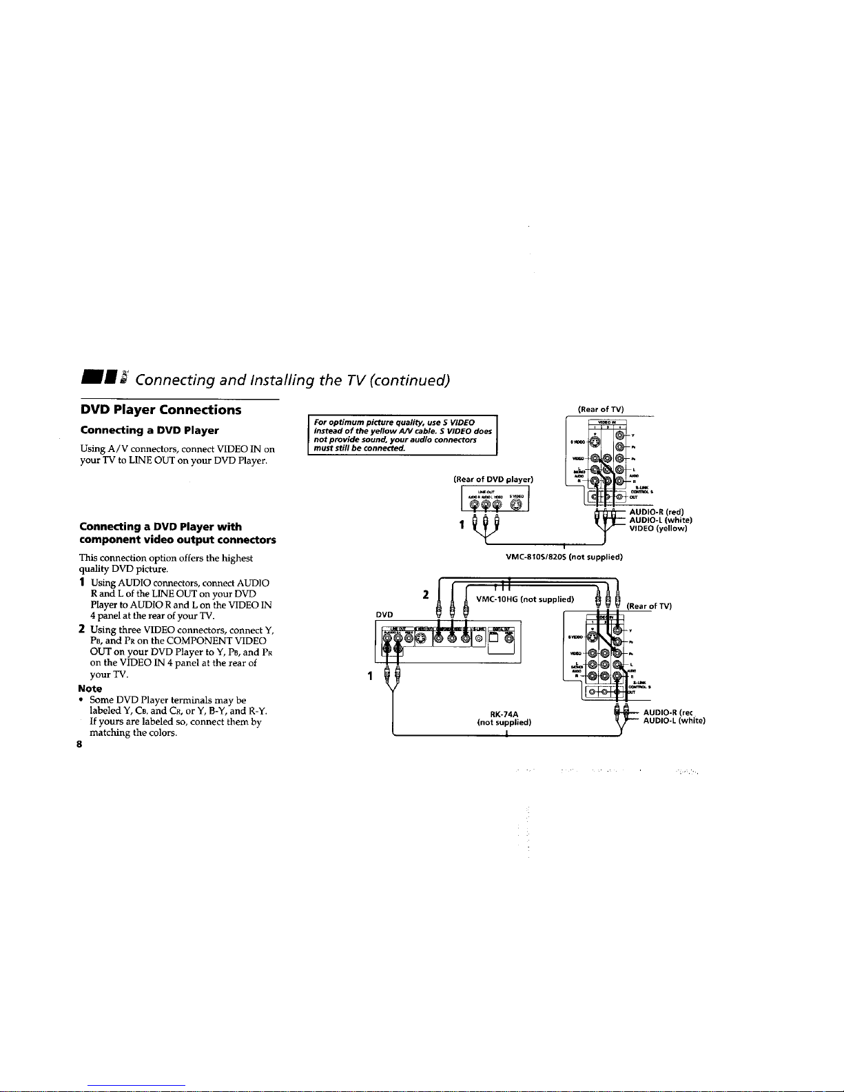
DVD Player Connections
Connecting a DVD Player
Using A/V connectors, connect VIDEO IN on
your TV to LINE OUT on your DVD Player.
Connecting a DVD Player with
component video output connectors
This connection option offers the highest
quality DVD picture.
1 Using AUDIO connectors, connect AUDIO
R and L of the LINE OUT on your DVD
Player to AUDIO R and L on the VIDEO IN
4 panel at the rear of your TV.
2 Using three VIDEO connectors, connect Y,
PB, and PR on the COMPONENT VIDEO
OUT on your DVD Player to Y, PB, and PR
on the VIDEO IN 4 panel at the rear of
your TV.
Note
• Some DVD Player terminals may be
labeled Y, CB, and CR, or Y, B-Y, and R-Y.
If yours are labeled so, connect them by
matching the colors.
8
For optimum picture quality, use S VIDEO
instead of the yellow AN cable. S VIDEO does
not provide sound, your audio connectors
must still be connected.
(Rear of DVD player)
(Rearof W)
A m
_ UDIO-R (red)
AUDIO-L (white)
VIDEO(yellow)
I
VMC-810S1820S (not supplied)
2
f Ill
DVD
,y
RK-74A
(not supplied)
l
(RearofTV)
-y
L
mm
_,_,
AUDIO-R (re(
AUDIO-L (white)
 Loading...