

Sony Walkman WM-FX277 Service Manual
Ver 1.0 2001.03
WM-FX277
SERVICE MANUAL
RADIO CASSETTE PLAYER
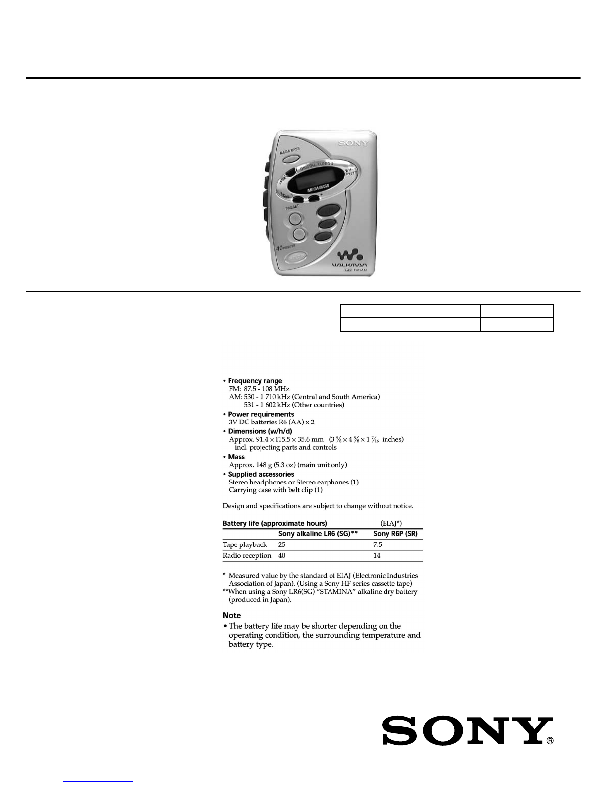
SPECIFICATIONS
E Model
Chinese Model
Model Name Using Similar Mechanism NEW
MD Mechanism Type MF-WMFX241-114
9-927-695-31
2001C0200-1
© 2001.3
Sony Corporation
Audio Entertainment Group
General Engineering Dept.

2
WM-FX277
Specifications ........................................................................... 1
1. SERVICING NOTE ...................................................... 3
2. GENERAL ...................................................................... 3
3. DISASSEMBLY
3-1. Cabinet (Front) ........................................................... 4
3-2. Main Board ................................................................. 4
3-3. Mechanism Deck ........................................................ 5
3-4. Belt, Capstan/reel Motor (M601),
Magnetic Head (Playback) (HP601) ........................... 5
3-5. Cassette Holder ........................................................... 6
4. ADJUSTMENTS
4-1. Mechanical Adjustments ............................................ 7
4-2. Electrical Adjustments ................................................ 7
5. DIAGRAMS
5-1. Explanation of IC Terminals ..................................... 10
5-2. Block Diagram ...........................................................11
5-3. Printed Wiring Boards – Main Section (Side A) – ... 12
5-4. Printed Wiring Boards – Main Section (Side B) – ... 13
5-5. Schematic Diagram ................................................... 14
6. EXPLODED VIEWS
6-1. Cabinet Section ......................................................... 17
6-2. Mechanism Deck Section (MF-WMFX241-114)..... 18
7. ELECTRICAL PARTS LIST ................................... 19
Flexible Circuit Board Repairing
• Keep the temperature of the soldering iron around 270°C during
repairing.
• Do not touch the soldering iron on the same conductor of the
circuit board (within 3 times).
• Be careful not to apply force on the conductor when soldering or
unsoldering.
Notes on chip component replacement
• Never reuse a disconnected chip component.
• Notice that the minus side of a tantalum capacitor may be damaged by heat.
TABLE OF CONTENTS
3
WM-FX277
SECTION 1
SERVICING NOTE
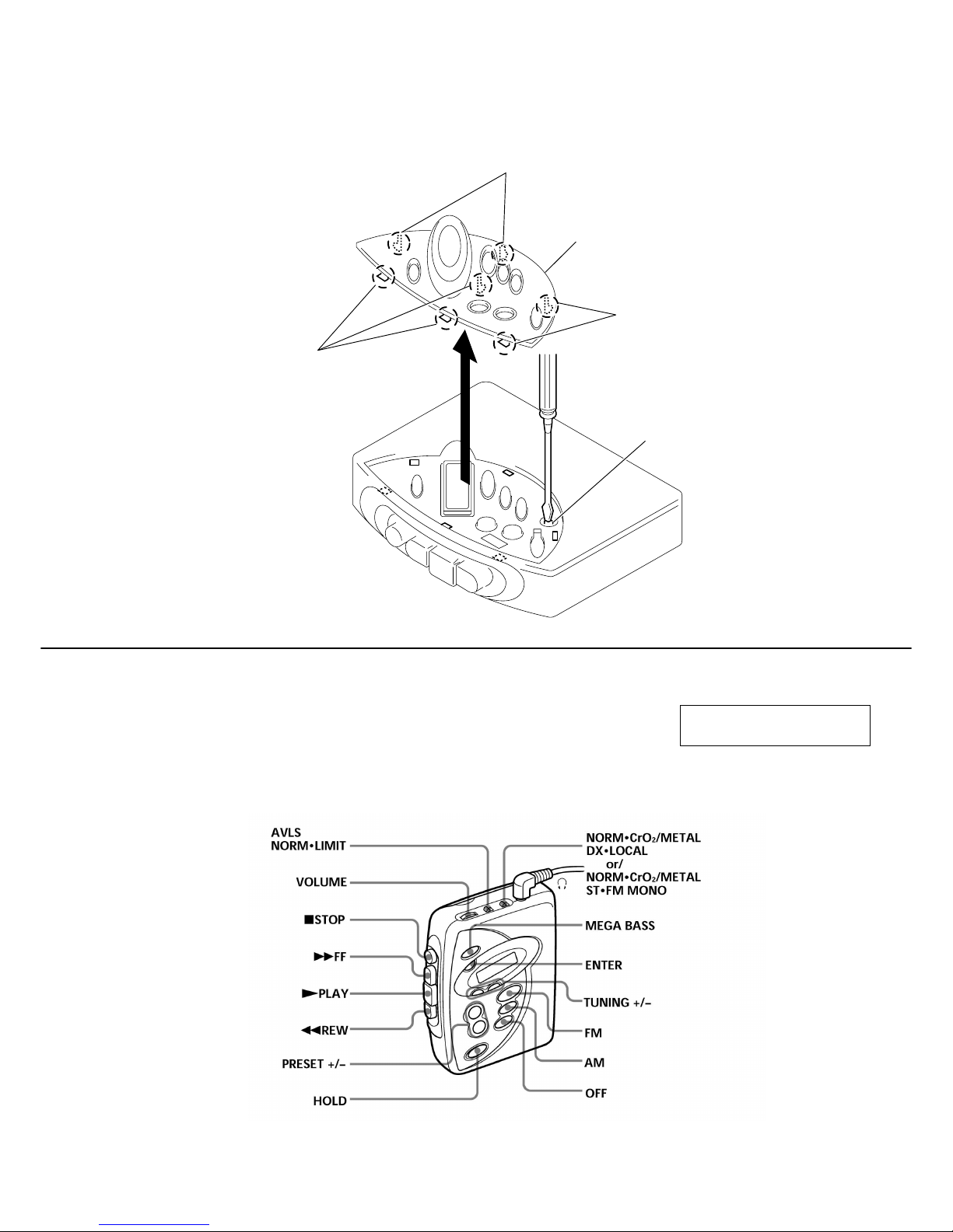
In case of adjusting Tape Speed, you can easily to adjust RV601 by removing 7 claws on Window (LCD) and itself as shown in the figure.
1.Insert the precision screwdriver (Cover a point by cloth) in to the slit at claw.
2.Remove the window(LCD).
Note: Be careful not to damage claws.
Claws
Window(LCD)
Claws
Claws
RV601
SECTION 2
GENERAL
This section is extracted from
instruction manual.
LOCATION AND FUNCTION OF CONTROLS
4
WM-FX277
SECTION 3
DISASSEMBLY
Note : Follow the disassembly procedure in the numerical order given.
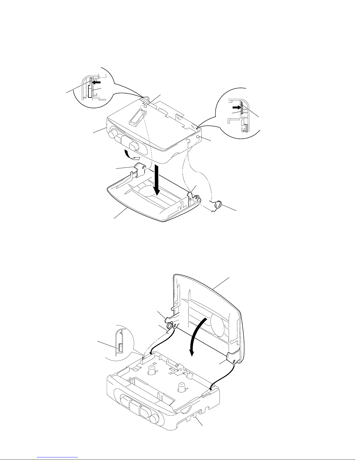
3-1. CASSETT HOLDER ASSY, CABINET (FRONT)
3-2. MAIN BOARD
• The equipment can be removed using the following procedure.
Main boardCassette holder ASSY
Cabinet (Front)
Cassette holder
Mechanism deck Belt, Capstan/reel motor (M601),
Magnetic head (Playback) (HP601)
Set
Cabinet (Front)
Cassette holder ASS
Y
4
Claws
4
Claw
2
5
1
Claws
1
Claws
3
Claws
1
Claws
Main board
1
Screw
Orange
Black
White
Red
Cassette holder ASS
Y
Head flexible board
2
Remove solder
3
Claws
4
Note : Use the precision driver with coverd a point
by cloth to release the claw.
Be careful not to damage claws.
5
WM-FX277
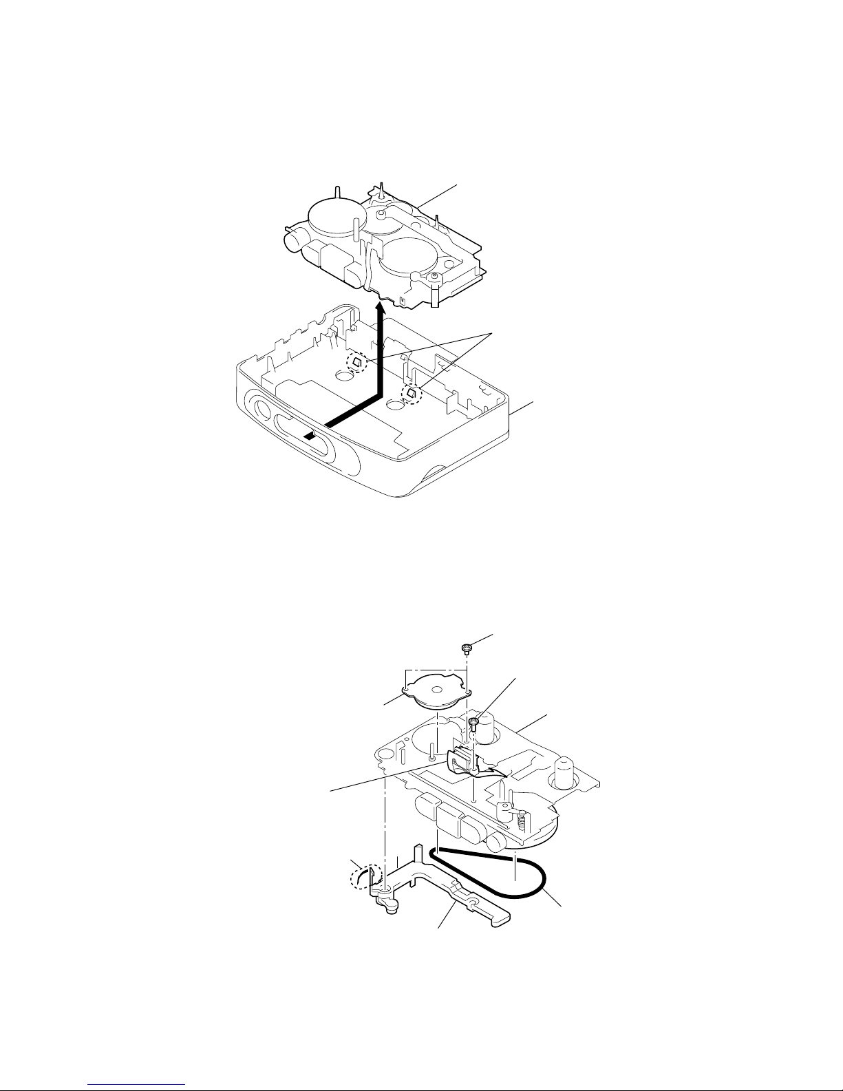
3-3. MECHANISM DECK
3-4. BELT, CAPSTAN/REEL MOTOR (M601), MAGNETIC HEAD (PLAYBACK)(HP601)
Mechanism deck
Cassette holder ASS
Y
1
Claws
2
2
Belt
Stopper
1
Claw
6
magnetic head
(PLAYBACK)
(HP601)
4
Capstan/reel motor
(M601)
3
Screws (M1.4)
5
Screws (M1.4)
Mechanism dec
k
6
WM-FX277
1 Insert the spring (torsion) to the L shape slot as shown in the figure.
2,3 Insert the hinge of the “Cassette holder ”.
4 Close the “Cassette holder” then press it.
3-5. CASSETTE HOLDER
z
CAUTIONS DURING ASSEMBLY
Cassette holder
4
Spring (torsion)
Hinge
Hinge
Projection
1
5
Hinge
Cabinet (center)
Hinge
Projection
Projection
Projection
3
Move the hinge away
from projection
2
Move the hinge away
from projection
Spring (torsion)
L shape slot
Hinge
Hinge
Cassette holde
r
Cabinet (center)
1
2
4
3
7
WM-FX277
4-1. MECHANICAL ADJUSTMENTS
PRECAUTION
1. Clean the following parts with a denatured-alcohol-moistened
swab :
playback head pinch roller
capstan rubber belt
2. Demagnetize the playback head with a head demagnetizer.
Do not use a magnetized screwdriver for the adjustments.
3. These measurement and adjustment should be performed with
the rated power supply voltage (2.5 V) unless otherwise noted.
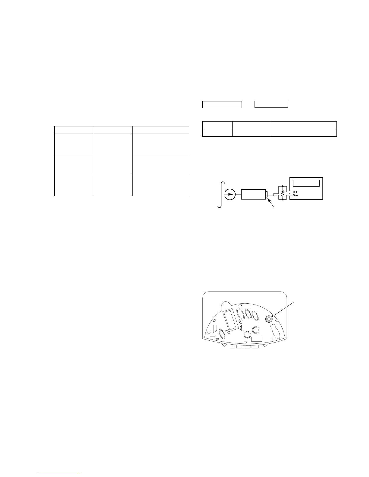
Torque Measurement
Mode Torque meter Meter reading
FWD
1.97 to 4.90 mN•m
20 to 50 g • cm
CQ-102C
(0.28 to 0.69 oz• inch)
FWD
less than 0.19 mN•m
less than 2 g • cm
back tension (less than 0.027 oz• inch)
FF, REW CQ-201B
5.89 to 19.61 mN•m
60 to 200 g • cm
(0.84 to 2.77 oz• inch)
SECTION 4
ADJUSTMENTS
4-2. ELECTRICAL ADJUSTMENTS
PRECAUTION
• Supplied voltage : 2.5V.
• Switch and control position
MEGA BASS (S709) : OFF
VOLUME control (RV301) : maximum
AVLS (S304) : NORM
TAPE SECTION
Test Tape
Type Signal Used for
WS-48A 3kHz, 0dB Tape Speed Adjustment
Tape Speed Adjustment
Procedure :
1. Playback WS-48A (tape center part) and adjust RV601 so that
the frequency counter reading becomes 3,000Hz.
Standard value : 2,985–3,015Hz
2. Playback WS-48A (tape top and end) .
Check that frequency counter reading is within ±1.0% of the
reading of step 1.
Adjustment Location :
0 dB = 0.775V
set
test tape
WS-48A
(3kHz, 0dB)
frequency counte
r
16
Ω
phones jack (J301)
RV601:
Tape speed Adjustmen
t
Refer to page 3 for Servicing note
 Loading...