

Sony WALKMAN WM-FS420RS, WALKMAN WM-FS420 Service Manual
WM-FS420/FS420RS
US Model
Canadian Model
WM-FS420/FS420RS
AEP Model
E Model
WM-FS420
SERVICE MANUAL
RADIO CASSETTE PLAYER
SPECIFICATIONS
Model Name Using Similar Mechanism NEW
Tape Transport Mechanism Type MF-WMFS420-114
Radio Frequency FM : 87.5 – 108 MHz
AM : 530 – 1,710 kHz
(North, Central and South America)
531 – 1,602 kHz (Other countries)
Power Requirements 3 V DC Batteries R6 (AA) × 2
Dimensions (w/h/d) Approx. 108.4 × 125.7 × 47.2 mm
(4 3/8 × 5 × 1 7/8 inches) incl.
projecting parts and controls
Mass Approx. 280 g (9.9 oz)/Approx. 355 g (12.6 oz)
(incl. batteries and a cassette)
Supplied Accessories • Stereo headphones or earphones (1)
• Belt clip (1)
• Battery charger (1) (FS420RS only)
• Rechargeable battery
NC-WMAA, 1.2 V, 700 mAh, Ni-Cd (2) (FS420RS only)
• Rechargeable battery carrying case (1) (FS420RS only)
Design and specifications are subject to change without notice.
Ver 1.2 2001. 03
Sony Corporation
Audio Entertainment Group
General Engineering Dept.
9-927-679-12
2001C1600-1
© 2001.3
— 2 —
TABLE OF CONTENTS
Notes on chip component replacement
• Never reuse a disconnected chip component.
• Notice that the minus side of a tantalum capacitor may be
damaged by heat.
Flexible Circuit Board Repairing
• Keep the temperature of soldering iron around 270˚C
during repairing.
• Do not touch the soldering iron on the same conductor of the
circuit board (within 3 times).
• Be careful not to apply force on the conductor when soldering
or unsoldering.
SECTION 1
GENERAL
This section is extracted
from instruction manual.
1. GENERAL ··········································································2
2. SERVICE NOTE······························································· 3
3. DISASSEMBLY
3-1. Main Assembly ······························································ 4
3-2. Chassis Sub Assy··························································· 5
3-3. Main Board and Mechanism Deck ································ 5
3-4. Belt ················································································ 6
3-5. Head, Magnetic (HP901) ··············································· 6
4. MECHANICAL ADJUSTMENT ·································· 7
5. ELECTRICAL ADJUSTMENT ···································· 7
6. DIAGRAMS
6-1. IC Block Diagrams ······················································ 10
6-2. Block Diagram ···························································· 11
6-3. Schematic Diagram ····················································· 13
6-4. Printed Wiring Board··················································· 15
6-5. IC Pin Function Description ········································ 17
7. MEXPLODED VIEWS
7-1. Cabinet Assy Section··················································· 18
7-2. Main Board Section ····················································· 19
7-3. Mechanism Deck Section-1
(MF-WMFS420-114) ·················································· 20
7-4. Mechanism Deck Section-2
(MF-WMFS420-114) ·················································· 21
8. ELECTRICAL PPARTS LIST···································· 22
— 3 —
SECTION 2
SERVICE NOTE
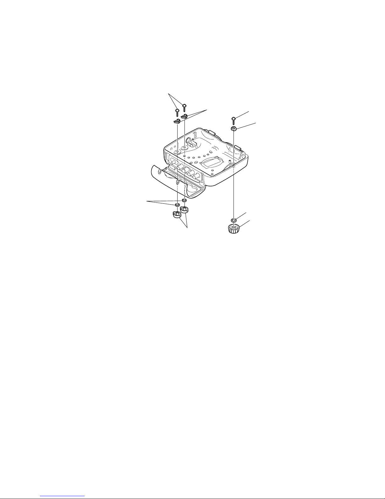
WATER PROOF SECTION
Note : In case the parts in the figure are removed for repair, treat them to protect from water drop following the instructions in the figure
(spread grease, bond etc.)
• Sony grease SGL-601 : 7-651-000-10
Tapping screw (B)(1.4 × 4)
Tapping screw (B)(1.4
×
4)
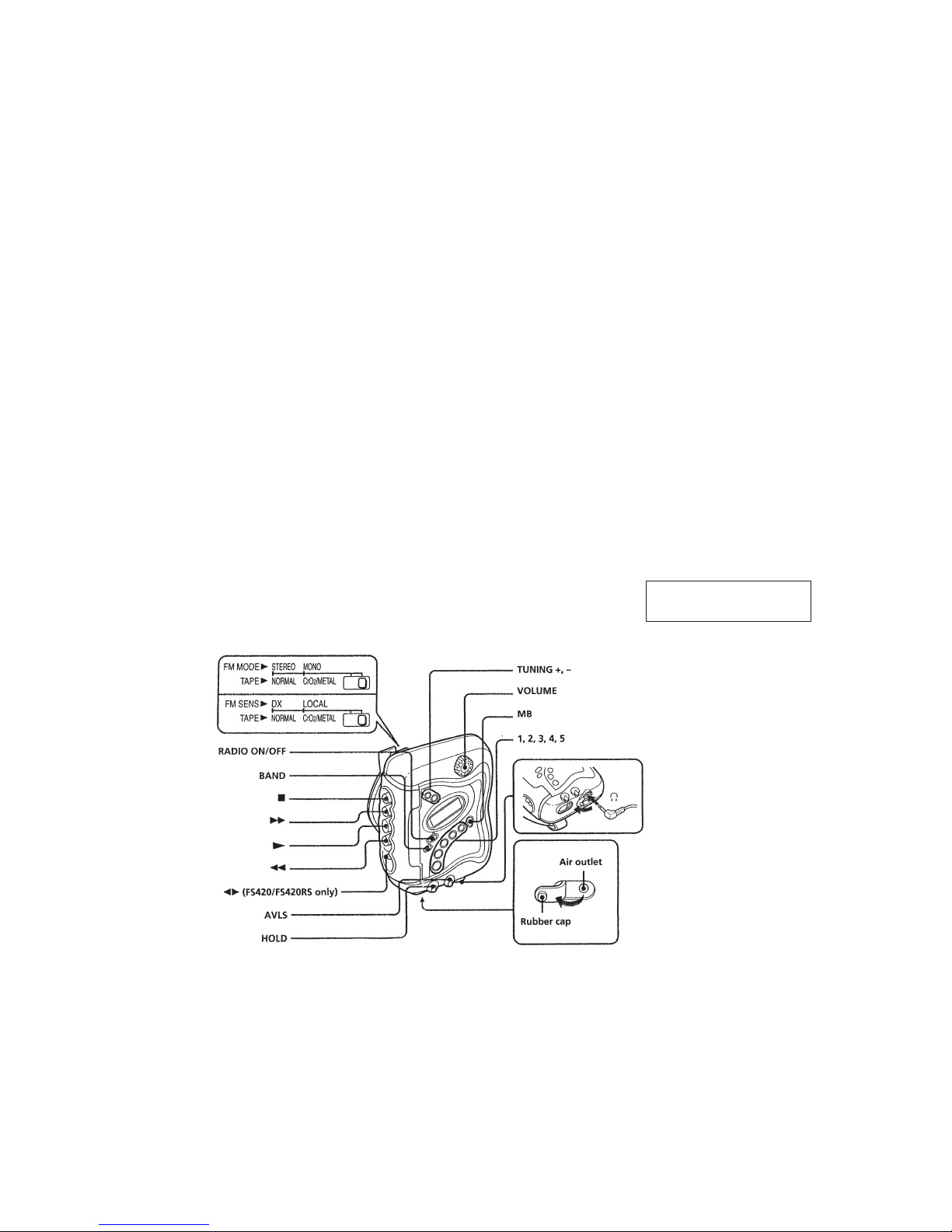
Joint (AVLS)
Joint (VOL)
Knob (Hold)
Knob (Vol)
Ring. O
(Apply sony grease: SGL-601
)
Ring (Dia. 2.5 × Dia. 4.5). O
(Apply sony grease: SGL-601)
— 4 —
SECTION 3
DISASSEMBLY
Note : Follow the disassembly procedure in the numerical order given.
Set
Main Assembly
Chassis Sub Assy
Main Board and Mechanism Deck
Belt
Head, Magnetic (HP901
)
Note : Disassemble the unit in the order as shown below.
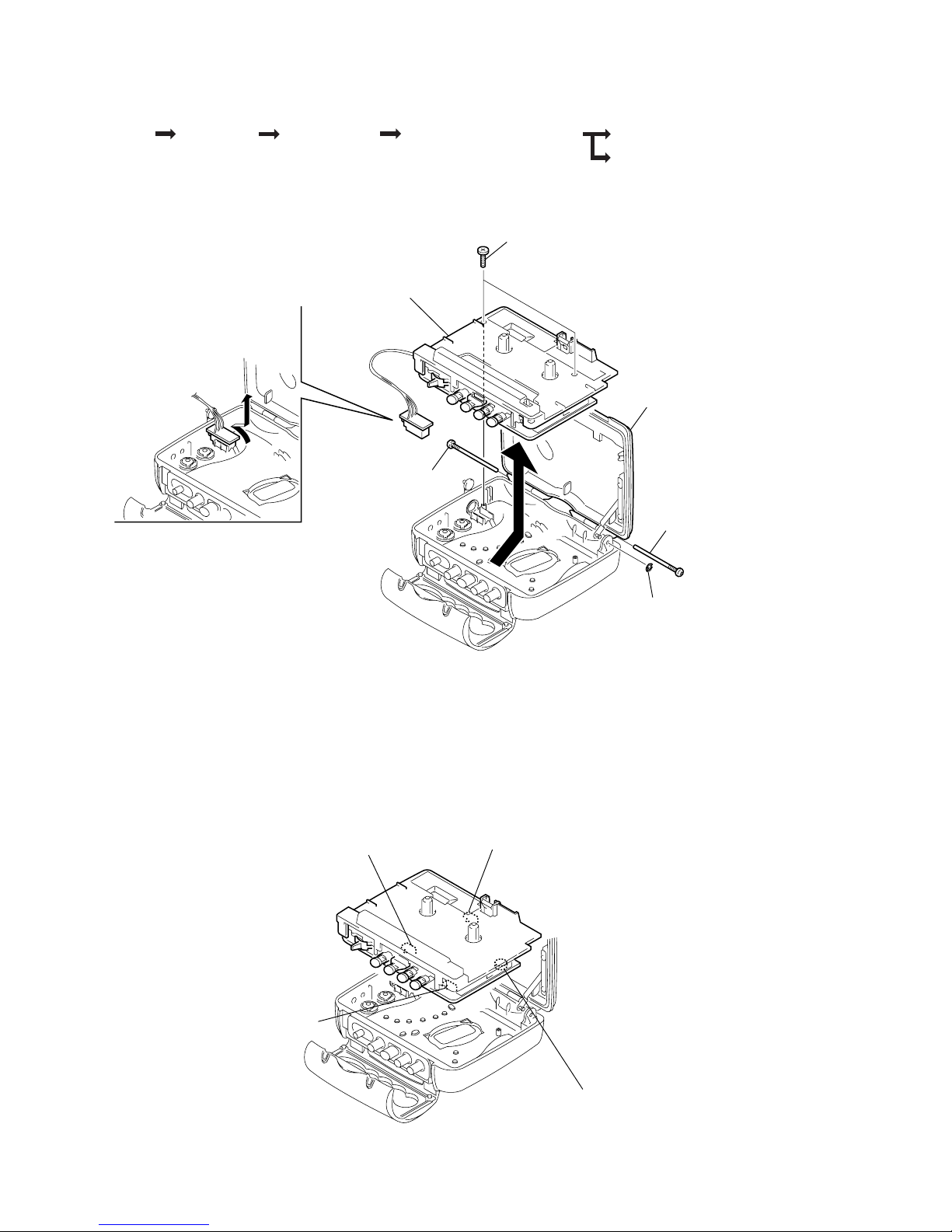
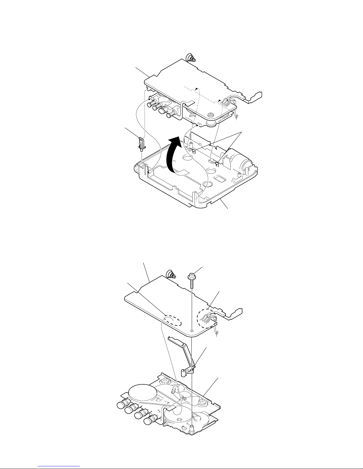
3-1. MAIN ASSEMBLY
6
Remve the main assembly in the direction
of arrow.
(Be careful not to focibly pull the wire that connects
the main board and the headphone board.)
7
Remove the headphone
borad in the direction of arrow.
1
Stop ring (E 1.2)
5
Two screws (+B1.7 × 7)
3
Screw, tapping
2
Screw, tapping
4
Cassette sub assembly, holde
r
CAUTION WHEN ASSEMBLING THE MAIN ASSEMBLY
• Assemble the main assembly in a way that each switch mates with the corresponding knob each other.
DIR switch (S301)
POWER switch (S303)
DX/LOCAL switch
(S304)
Volume (RV301
)
— 5 —
3-2. CHASSIS SUB ASSY
Main board
2
Knob (DX-Local)
1
Two claw
s
3
Chassis sub assy
3-3. MAIN BOARD AND MECHANISM DECK
3
Screw (M1.4 ) Toothed Lock
1
Remove the solder (fouf points)
5
Stopper (MD)
4
Main board
2
Remove the solder
6
Mechanism deck
— 6 —
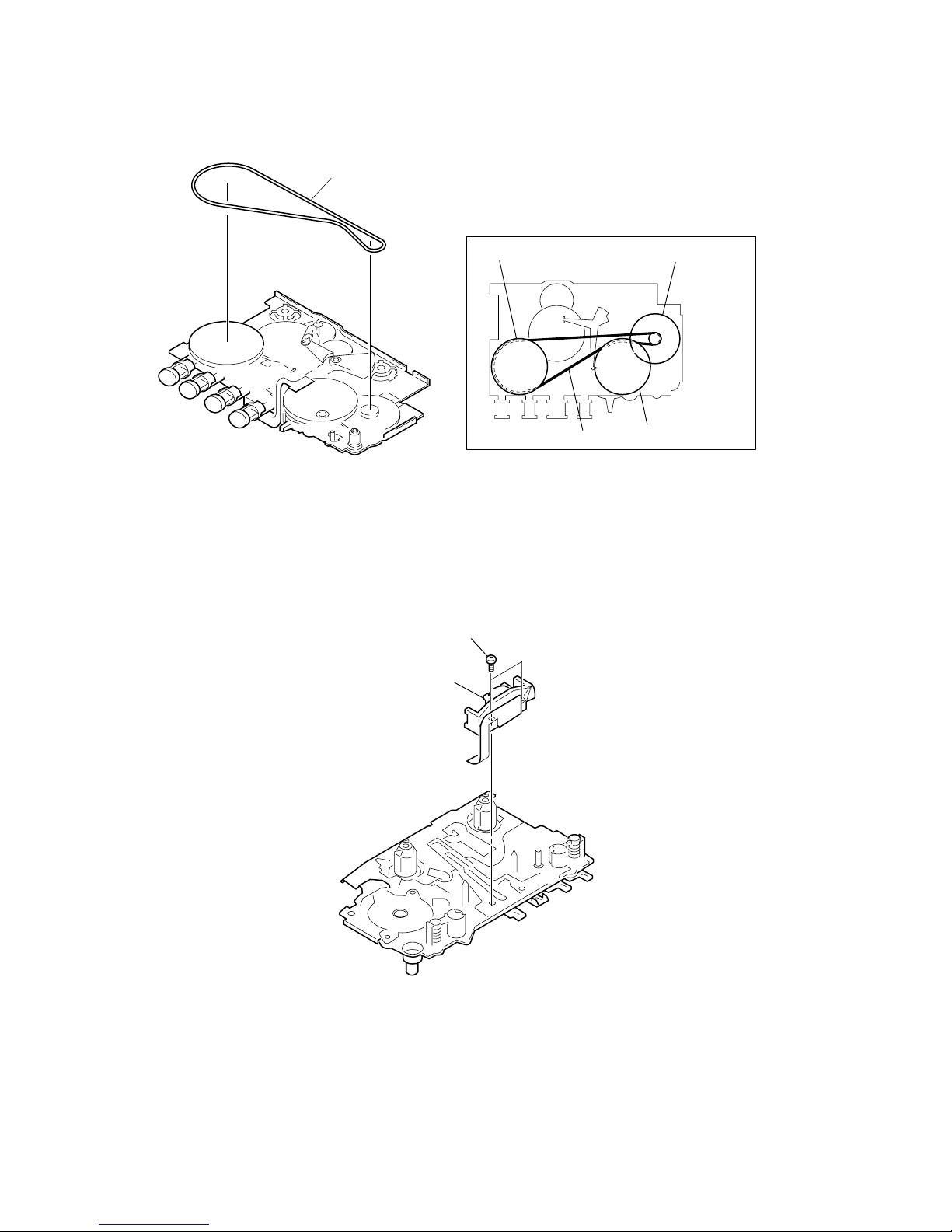
3-4. BELT
Reel/Capstan motor
Capstan wheel assy(SP)
Capstan wheel assy(SP)
Belt threading
Belt
Belt
3-5. HEAD, MAGNETIC (HP901)
1
Two screws (M1.4)
2
Head, magnetic (HP901)
— 7 —
SECTION 4
MECHANICAL ADJUSTMENT
SECTION 5
ELECTRICAL ADJUSTMENT
PRECAUTION
1. Clean the following parts with a denatured-alcohol-moistened
swab:
playback head pinch roller
rubber belts capstan
2. Do not use a magnetized screwdriver for the adjustments.
Torque Measurement
Mode
FWD
FWD
Back Tension
FF, REW
Torque Meter
CQ-102C
CQ-102C
CQ-201B
Meter Reading
20 to 42 g•cm
(0.27 to 0.58 oz•inch)
More than 2.0 g•cm
(More than 0.027 oz•inch)
More than 50 g•cm
(More than 0.69 oz•inch)
TAPE SECTION
Signal
3 kHz, 0 dB
Used for
Tape speed adjustment
Tape
WS-48A
Test T ape
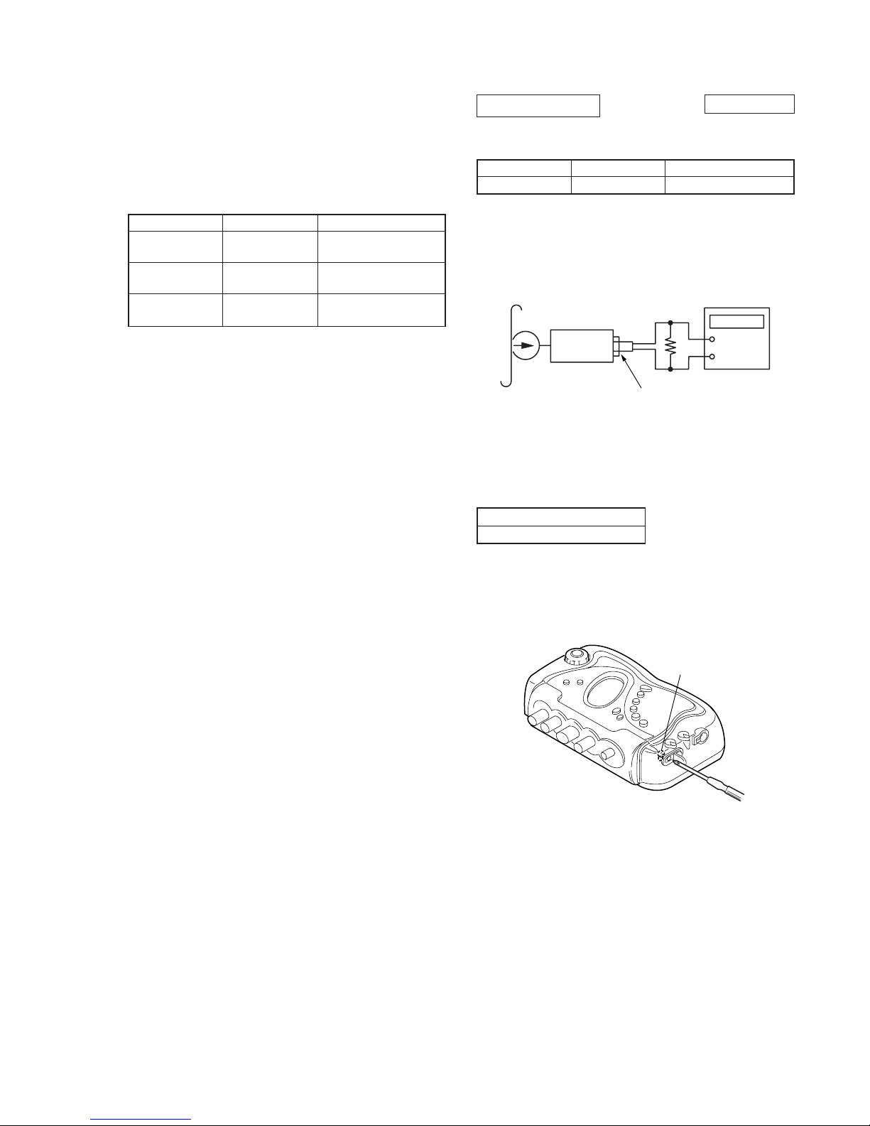
Tape Speed Adjustment
Procedure:
Mode: Playback
Adjustment V alue: normal tape speed
Adjust the tape speed adjustment R V601, so that the freqency counter
reading becomes 3,000Hz.
Specification V alue:
Frequency difference between the beginning and the end of the tape
should be within 1.5 % (45 Hz).
Adjustment Location:
Test tape
WS-48A
(3 kHz, 0 dB)
Set
J301 (phones)
16
Ω
digital frequency
counter
+
–
Digital frequency counter
2,970 to 3,030 Hz
0 dB = 0.775 V
RV601
 Loading...