

Sony Walkman WM-EX500, Walkman WM-EX505 Service Manual
MICROFILM
SERVICE MANUAL
CASSETTE PLAYER
AEP Model
WM-EX500/EX505
E Model
WM-EX505
Model Name Using Similar Mechanism NEW
T ape Transport Mechanism Type MT-WMEX505-162
SPECIFICATIONS
WM-EX500/EX505
Dolby noise reduction manufactured under license
from Dolby Laboratories Licensing Corporation.
“DOLBY” and the double-D symbol ; are trademarks of Dolby Laboratories Licensing Corporation.
Photo: WM-EX505
• Frequency response (Dolby NR off (WM-EX505))
Playback: 30 - 18,000 Hz
• Output
Headphones (i jack)
Load impedance 8 - 300 ohms
• Power requirements
1.5 V
One R6 (size AA) battery
• Dimensions (w/h/d)
Approx. 78.7 x 109.7 x 28.1 mm, incl. projecting parts and
controls
• Mass
Approx. 145 g
Approx. 200 g (incl. a battery and a cassette)
• Supplied accessories
Stereo headphones or earphones with remote control (1)
(WM-EX505)
Stereo headphones or earphones (1) (WM-EX500)
Design and specifications are subject to change without notice.
Battery life (Approx. hours) (EIAJ*)
Sony alkaline LR6 (SG)
Tape playback 35
* Measured value by the standard of EIAJ (Electronic
Industries Association of Japan). (Using a Sony HF series
cassette tape)
Note
• The battery life may shorten depending on the
operation of the unit.
Ver 1.0 2000. 01

– 2 –
TABLE OF CONTENTS
1. SERVICING NOTES ............................................... 3
2. GENERAL ................................................................... 5
3. DISASSEMBLY ......................................................... 6
4. MECHANICAL ADJUSTMENTS....................... 12
5. ELECTRICAL ADJUSTMENTS......................... 12
6. DIAGRAMS
6-1. Block Diagram ................................................................ 13
6-2. Printed Wiring Board ...................................................... 15
6-3. Schematic Diagram ......................................................... 17
6-4. IC Pin Function Description ........................................... 22
7. EXPLODED VIEWS ................................................ 24
8. ELECTRICAL PARTS LIST ............................... 26
Flexible Circuit Board Repairing
• Keep the temperature of the soldering iron around 270 ˚C during repairing.
• Do not touch the soldering iron on the same conductor of the
circuit board (within 3 times).
• Be careful not to apply force on the conductor when soldering
or unsoldering.
Notes on chip component replacement
• Never reuse a disconnected chip component.
• Notice that the minus side of a tantalum capacitor may be damaged by heat.
– 3 –
SECTION 1
SERVICING NOTES
This set detects the rotation of the idler gear (A) (side S) using the
PH701 (photo reflector). The PH701 is mounted on the MAIN
board, therefore the idler gear (A) (side S) cannot be detected with
the MAIN board removed. As a r esult, the motor (M901) cannot
be controlled, causing malfunction.
Further, the DIRECTION switch (S701) is also mounted on the
MAIN board, and with the board removed, the mechanism position cannot be detected and the operation is not changed over.
Therefor, when the voltage check is e xecuted with the MAIN board
removed, follow the procedure provided below.
1. Setting
(1) Refer to “3. DISASSEMBLY”, and remove the MAIN board.
(2) Connect the MAIN board to the motor (M901) and the
plunger (PM901) using jumper wires. These can be connected
easily with the use of the extension tool (Part No. 1-769143-11) (ten in one set).
(3) Short the TAPE DETECT switch (S901-1) terminals and the
ATS switch (S901-2) terminals.
(4) Connect the AF oscillator to the TP36 (PHOTO IN) and the
TP46 (GND).
(5) Supply 1.3 V to the battery terminals using the regulated
power supply.
2. Preset state
T o set the PLAY , FF, REW modes, the preset state must be set.
(1) Check that the slider (NR) and the DIRECTION switch
(S701) are set to the center position. If not, set the preset
state as follow.
(2) Move the DIRECTION switch (S701) to the side, which the
slider (NR) is facing.
(3) The slider (NR) will move when the regulated power supply
switch is set to OFF once and then set to ON. Move the DIRECTION switch (S701) according to this timing and set to
the center position.
3. FF, REW modes
(1) Check that the preset state is set.
(2) Input the square wave or sine wave to the TP36 (PHO TO IN)
and the TP46 (GND).
(3) Press the x button (S702) to set the STOP mode.
(4) Press the [FF AMS] button (S704) or the [REW AMS] but-
ton (S705).
4. PLAY mode
(1) Check that the preset state is set.
(2) Input the square wave or sine wave to the TP36 (PHO TO IN)
and the TP46 (GND).
(3) Press the x button (S702) to set the STOP mode.
(4) Press the [ REPEAT] button (S703) will move the
slider (NR) once towards the side R and then to the side F.
Move the DIRECTION switch (S701) according to this
timing will set the PLAY mode (side F). Press the
[ REPEAT] button (S703) another time and move the
DIRECTION switch (S701) according to the movement of
the slider (NR) will set the PLAY (R mode).
Note 1: If the above fails, perform from preset again.
Note 2: Use the [ REPEAT] (S703), x (S702), [FF AMS]
(S704), and [REW AMS] (S705) buttons on the remote controller as much as possible. If no remote controller, do not touch the
buttons with your hands, but using a stick with a round tip.
Note 3: When using headphones, the timing for move the DIRECTION
switch (S701) can be determined from the beep sound.
n N
+
–
square wave
(sine wave)
10 Hz, – 3.5 dB
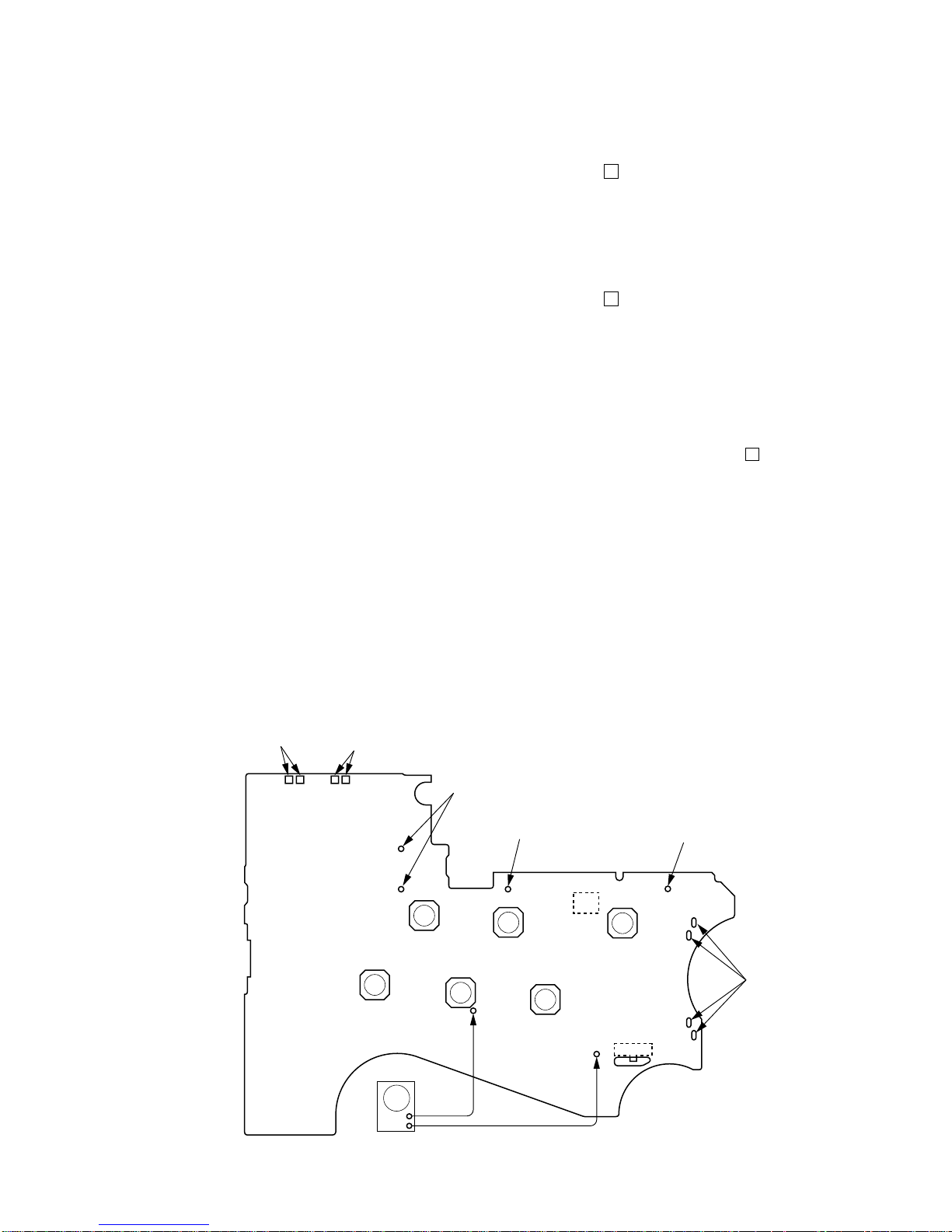
– MAIN Board (Side B) –
TAPE DETECT
switch
(S901-1)
ATS switch
(S901-2)
connect to the plunger
(PM901)
battery
terminal 3
battery
terminal #
connect to th
e
motor (M901)
PH701
SOUND
(S706)
S701
DIRECTION
FWDTCENTERtREV
TP46
(GND)
FUNCTION
(S708)
x
(S702)
TP36
(PHOTO IN)
REW AMS
(S705)
YREPEAT
(S703)
FF AMS
(S704)
AF oscillator
n N
n N
– 4 –
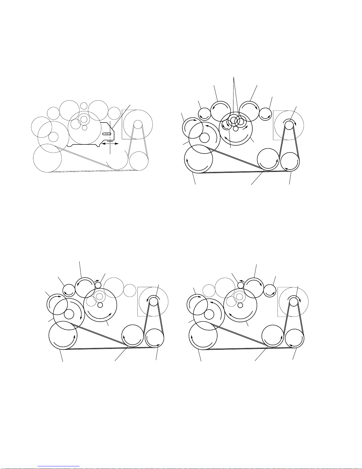
SLIDER (NRA) Rotation system
Rotation system during PLAY
Rotation system during FF Rotation system during REW
slider (NRA)
side F
side R
center
insert flywheel (N)
insert flywheel (R)
reverse pulley
clutch assy (F)
g
ear (Y)
cam gear
gear (REEL)
(T side)
motor pulley
idler (A) gear (T side)
gear (FR)
(FF: left side)
insert flywheel (N)
insert flywheel (R)
reverse pulley
clutch assy (F)
gear (Y)
cam gear
gear (REEL) (T side)
motor pulle
y
idler (A) gear (T side)
gear (NR)
(FWD: left side
REW: right side)
idler (B) gear
idler (A) gear (S side)
gear (REEL) (S side)
insert flywheel (N)
insert flywheel (R)
reverse pulley
clutch assy (F)
gear (Y)
cam gear
motor pulley
gear (FR)
(REW: right side)
idler (A) gear (S side)
gear (REEL) (S side)
– 5 –
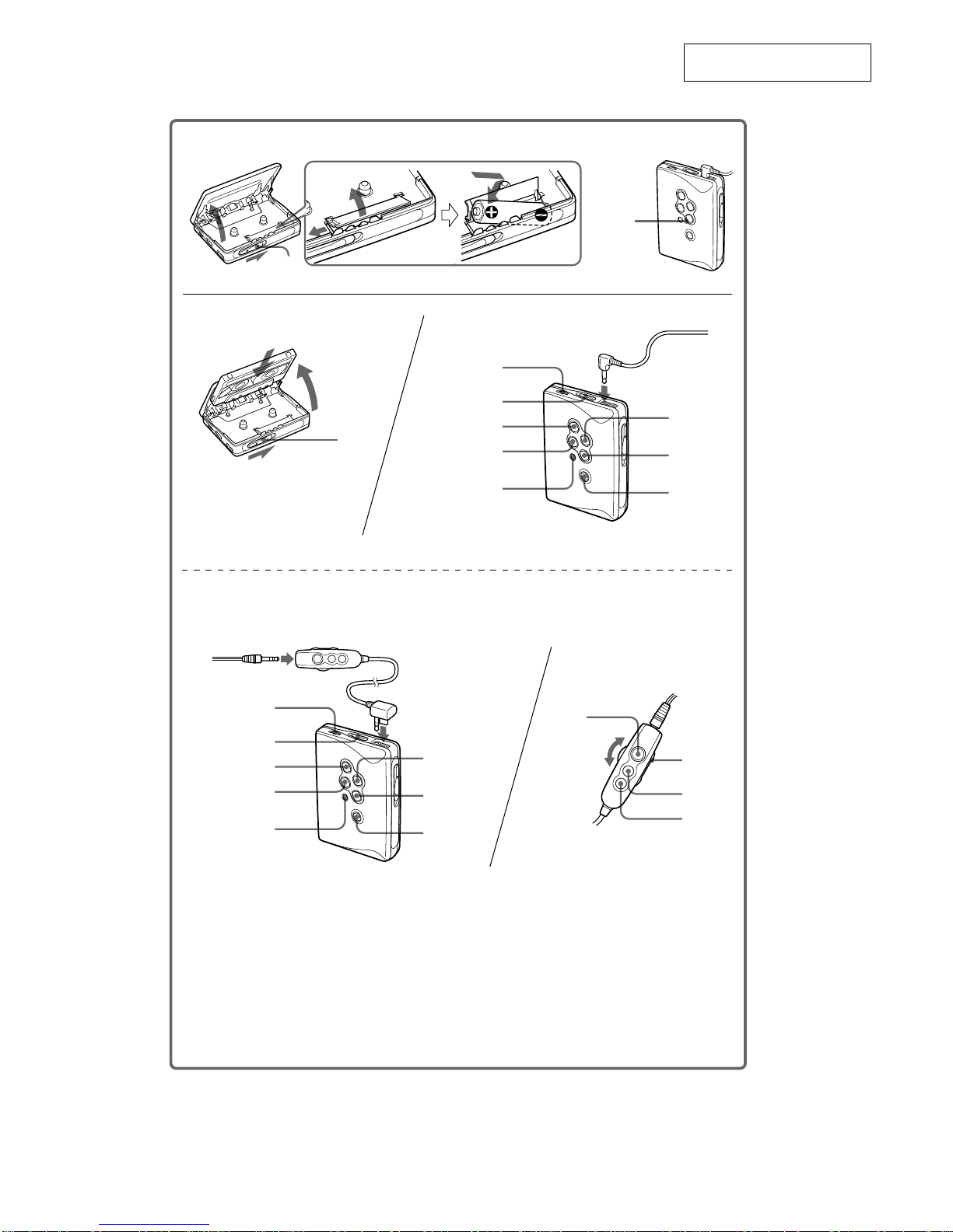
SECTION 2
GENERAL
This section is extracted from
instruction manual.
OPEN
OPEN
Y•REPEAT
x
REW(AMS•AVLS)
FUNCTION
SOUND
VOL
HOLD
FF (AMS•
BL SKIP/s)
B
A
BATT
VOL
REW
FF
Y•x
Y•REPEAT
x•;NR
FF (AMS•
BL SKIP/s)
REW (AMS•AVLS)
FUNCTION
SOUND
VOL
HOLD
HOLD
Plug in firmly.
Branchez fermement.
(WM-EX500)
(WM-EX505)
– 6 –
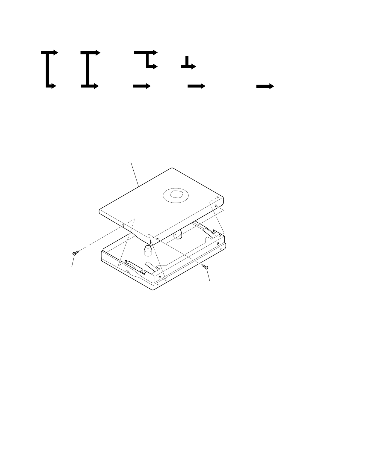
• This set can be disassembled in the order shown below.
SECTION 3
DISASSEMBLY
LID ASSY, CASSETTE
Note: Follow the disassembly procedure in the numerical order given.
Set Lid Assy,
Cassette
Main Board/Note for Installation
Holder (FS) Assy
Lever (N/R) Assy, Pinch
Head, Magnetic
(HP901)
Belt Motor (Capstan/Reel) (M901)
Ornament Assy
Case Assy
Holder, Battery
2 lid assy, cassette
1 two screws
(M1.4 × 2.0
)
1 screw
(M1.4 × 2.0)
– 7 –
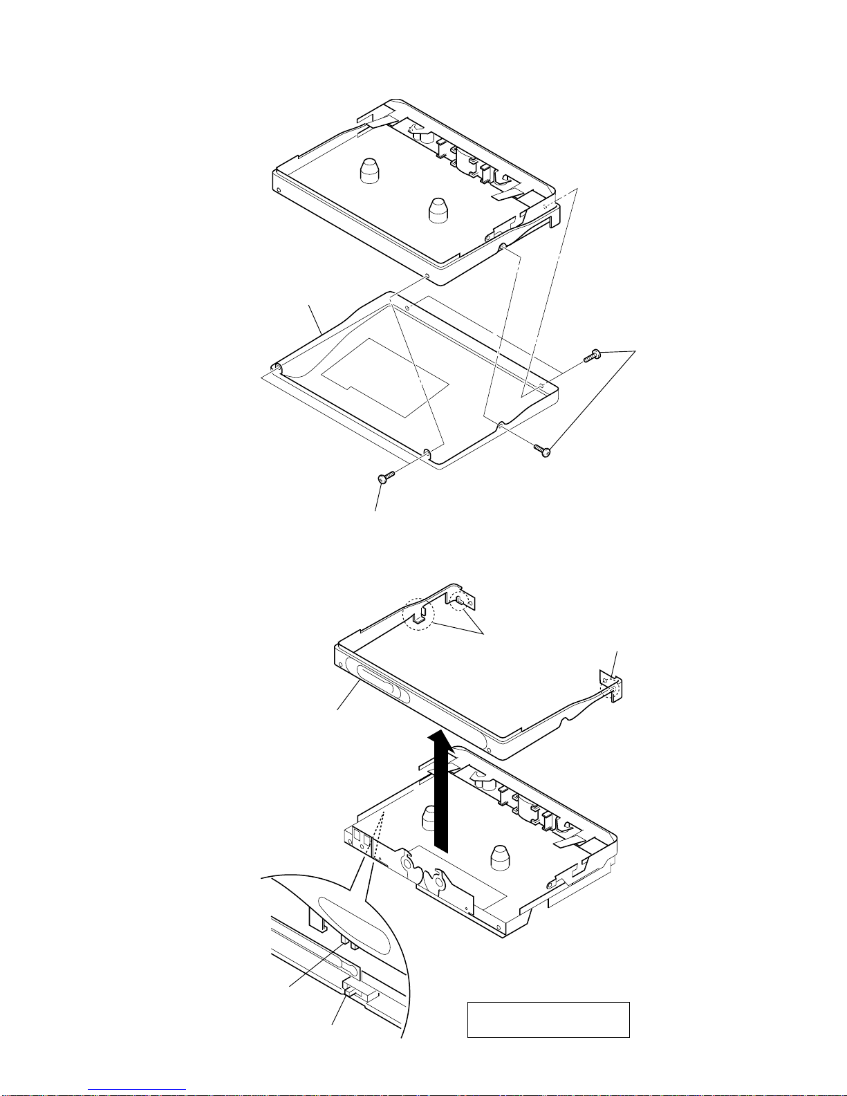
CASE ASSY
ORNAMENT ASSY
1 three screws
(M1.4 × 3.0)
1 two screws
(M1.4 × 3.0)
2 case assy
1 two claws
2 ornament assy
1 claw
knob (hold)
S707
On installation reel ornament,
adjust the S707 and knob (hold).
 Loading...