

Sony Walkman WM-EX170, Walkman WM-EX172 Service Manual
WM-EX170/EX172
Canadian Model
WM-EX170
AEP Model
E Model
WM-EX170/172
SERVICE MANUAL
CASSETTE PLAYER
MICROFILM
SPECIFICATIONS
Model Name Using Similar Mechanism NEW
T ape Transport Mechanism Type MT-WMEX170-1 14
Manufactured under license from Dolby Laboratories
Licensing Corporation.
“DOLBY” and the double-D symbol a are trademarks
of Dolby Laboratories Licensing Corporation.
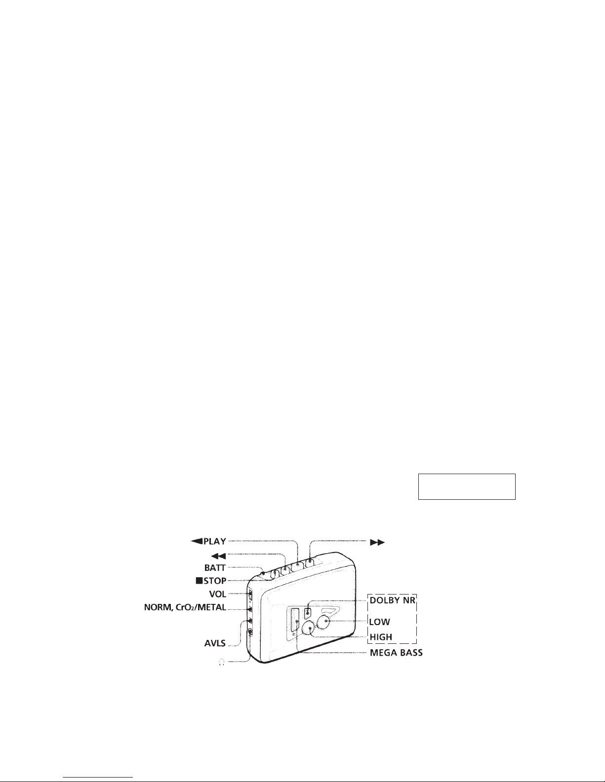
• Power requirements
3V DC batteries R6 (AA) × 2 / External DC 3V power sources
• Dimensions
88.5 × 111.5 × 37.6 mm
(3
1
/2 × 4 1/2 × 1 1/2 inches) (w / h/ d) incl. projecting parts and controls
• Mass
EX170 : Approx. 125 g (4.5 oz) / Approx. 185 g (6.6 oz) incl.
batteries and a cassette
EX172 : Approx. 130 g (4.6 oz) / Approx. 190g (6.8 oz) incl.
batteries and a cassette
• Supplied accessories
Stereo headphones or Stereo earphones (1) / Belt clip (1)
Design and specifications are subject to change without notice.
Photo : WM-EX172
— 2 —
TABLE OF CONTENTS
Flexible Circuit Board Repairing
• Keep the temperature of the soldering iron aroud 270˚ C during
repairing.
• Do not touch the soldering iron on the same conductor of the
circuit board (within 3 times).
• Be careful not to apply force on the conductor when soldering
or unsoldering.
Notes on chip component replacement
• Never reuse a disconnected chip component.
• Notice that the minus side of a tantalum capacitor may be
damaged by heat.
SECTION 1
GENERAL
1. GENERAL ······································································2
2. DISASSEMBLY
2-1. Cabinet (Front) Assy ··························································3
2-2. Main Board ········································································· 4
2-3. Cassette Lid ········································································4
2-4. Mechanism Deck ································································ 5
2-5. Belt, Motor (Reel/Capstan) ················································5
3. MECHANICAL ADJUSTMENT ······························ 6
4. ELECTRICAL ADJUSTMENT ································6
5. DIAGRAMS
5-1. Block Diagram ···································································7
5-2. Printed Wiring Board (EX170 Model) ······························· 9
5-3. Schematic Diagram (EX170 Model) ································ 11
5-4. Printed Wiring Board (EX172 Model) ····························· 13
5-5. Schematic Diagram (EX172 Model) ································ 15
5-6. IC Block Diagrams ··························································· 17
6. EXPLODED VIEWS
6-1. Cabinet Section································································· 18
6-2. Main Board Section ·························································· 19
6-3. Mechanism Section-1 (MT-WMEX170-114) ··················20
6-4. Mechanism Section-2 (MT-WMEX170-114) ··················21
7. ELECTRICAL PARTS LIST ···································22
This section is extracted
from instruction manual.
EX172 MODEL
— 3 —
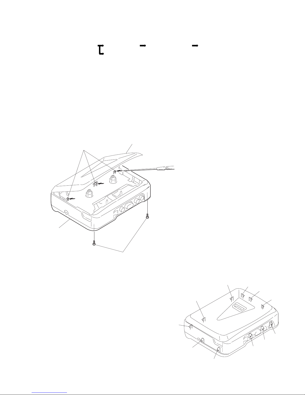
Cassette, lid
Cabinet (front) assy
A
1
T wo screws
[Screw (B1.7
×
9), tapping]
SECTION 2
DISASSEMBLY
Note : Follow the disassembly procedure in the numerical order given.
2-1. CABINET (FRONT) ASSY
2
Insert the precision screwdriver
(1.4 mm flat-blade) into the slit
at claw
A
and release the claw.
3
Remove the cabinet (front) assy.
(Release all claws
B
to L in
alphabetical order.)
• This set can be disassembled in the order shown below.
2-1. CABINET (FRONT) ASSY 2-2. MAIN BOARD
2-3. CASSETTE LID
2-4. MECHANISM DECK 2-5. BELT, MOTOR (REEL/CAPSTA
N)
B
L
K
C
D
E
F
G
H
I
J
— 4 —
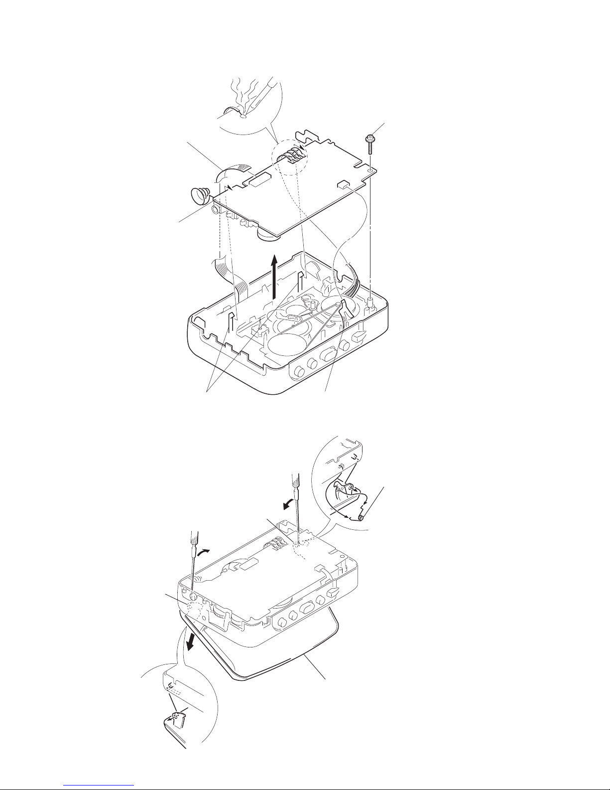
5
Spring (torsion)
B
A
1
Open the cassette lid.
4
Cassette lid.
2-2. MAIN BOARD
2-3. CASSETTE LID
2
Insert a precision screwdriver
(1.4 mm flat-blade) vertically
into portion
A
to release the
hinge plate.
3
Portion B to release the
hinge plate.
1
Head flexible board (CN301)
5
Two claws
6
MAIN board
3
Remove the four solders.
4
Screw (M1.4), toothed lock (WH
)
2
Flexible board (CN302)
— 5 —
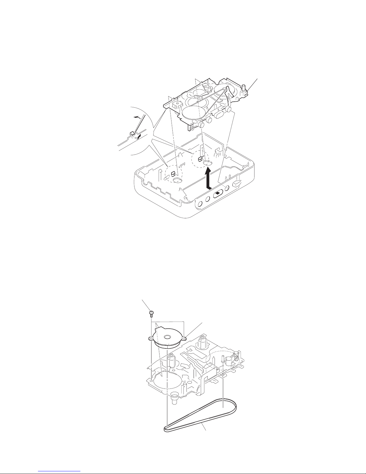
2
Two screw [screw (M1.4), special head]
3
Motor (reel/capstan
)
1
Belt
2-4. MECHANISM DECK
2-5. BELT, MOTOR (REEL/CAPSTAN)
1
Insert the precision screwdriver
(1.4 mm flat-blabe) in to the slit
and release two claws.
2
Remove the mechanism deck
in the direction of the arrow.
— 6 —
SECTION 3
MECHANICAL ADJUSTMENT
SECTION 4
ELECTRICAL ADJUSTMENT
PRECAUTION
1. Clean the following parts with a denatured-alcahol-moistened
sweb :
Playback head Pinch roller
Rubber belt Capstan
2. Demagnetize the playback head using a demagnetizer.
3. Do not use a magnetized screwdriver for adjustments.
4. After adjusting, apply screw-locking compound onto the
adjusted parts.
5. Unless specified otherwise, use a specified voltage (3.0V) to
perform the adjustments.
Torqu Measurement
Mode
FWD
FWD
Back Tension
REV
REV
Back Tension
FF
REW
Torqu meter
CQ-102C
CQ-102RC
CQ-201B
Meter reading
20 - 30 g · cm
0.4 - 2.0 g · cm
20 - 30 g · cm
0.4 - 2.0 g · cm
More than 40 g · cm
PRECAUTION
1. Specified voltage : 3.0V
2. Switch position
DOLBY NR switch : OFF (EX172 MODEL)
AVLS switch : NORM
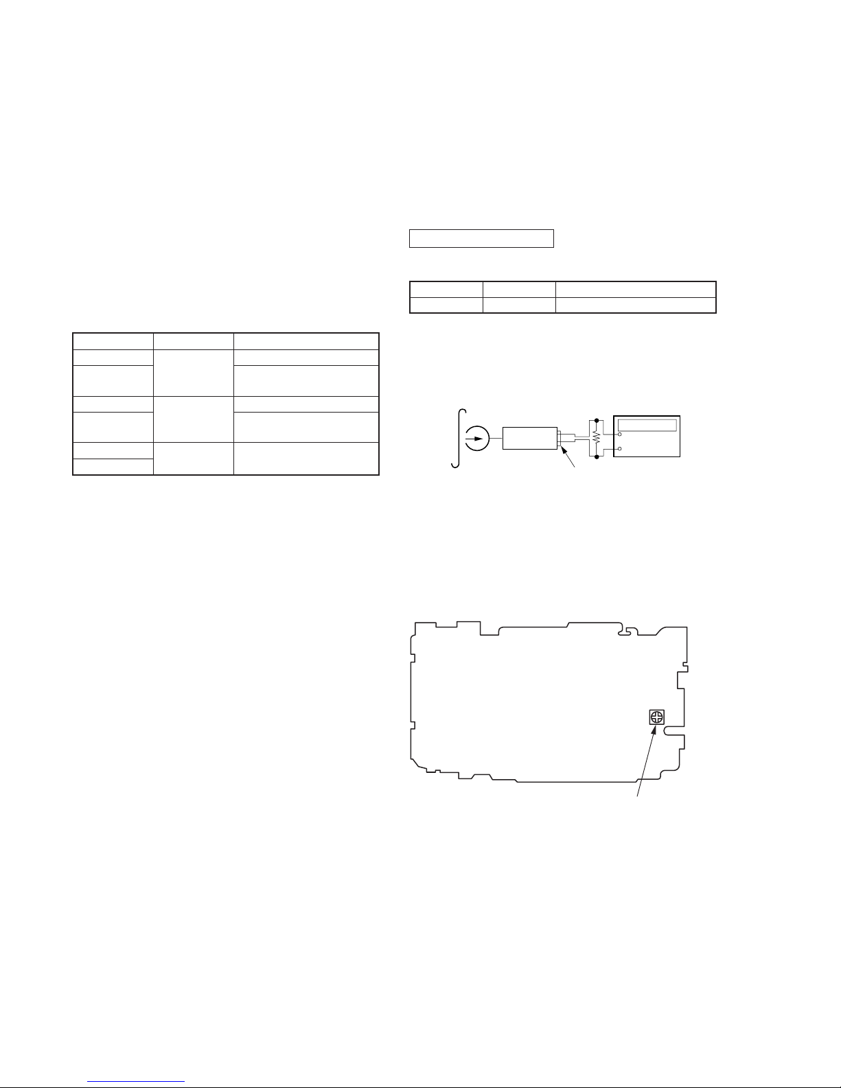
CASSETTE SECTION
T est Tape
T ape Speed Adjustmnet
Procedure :
1. Playback WS-48A (Tape center part) and adjust RV601 so that
the frequency counter reading becomes 3,000Hz ± 15Hz.
2. Playback WS-48A (Tape top and end).
Check that frequency counter reading is within 1.5% of the
reading of step1.
Adjustment Point :
[MAIN BOARD] —CONDUCTOR SIDE —
Type
WS-48A
Signal
3kHz, 0dB
Purpose
Tape Speed Adjustment
Test tape
WS-48A
(3kHz, 0dB)
Set
16
Ω
PHONES jack
+
–
Frequency counte
r
RV601: Tape speed
 Loading...