

Sony Walkman WM-DD 3 Service Manual
SERVICE
MANUAL
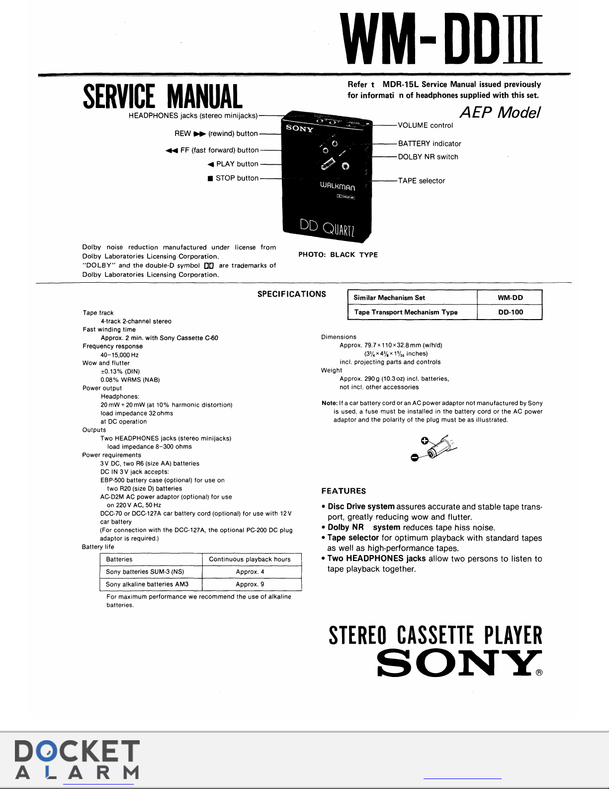
HEADPHONES jacks (stereo minijacks)
REW
11+
(rewind) button
~
FF (fast forward) button
~
PLAY button
• STOP button
Dolby
noise
reduction
manufactured
under
license
from
Dolby
Laboratories
Licensing
Corporation.
"DOLBY"
and
the
double-D
symbol
DO
are
trademarks
of
Dolby
Laboratories
Licensing
Corporation.
WM-DDill
Refer t MDR-15L Service Manual issued previously
for informati n
of
headphones supplied
with
this set.
PHOTO:
BLACK
TYPE
AEP
Model
VOLUME control
BATTERY indicator
DOLBY
NR
switch
TAPE selector
SPECIFICATIONS
Similar Mechanism
Set
WM-00
Tape track
4-track 2-channel stereo
Fast winding
time
Approx. 2 min.
with
Sony Cassette C-60
Frequency response
40-15,000
Hz
Wow and
flutter
±0.13% (DIN)
0.08% WRMS
(NAB)
Power
output
Headphones:
20
mW + 20
mW (at 10% harmonic distortion)
load impedance
32
ohms
at
DC
operation
Outputs
Two HEADPHONES jacks (stereo minijacks)
load impedance
8-300
ohms
Power requirements
3 V
DC,
two
R6
(size AA) batteries
DC
IN
3 V jack accepts:
EBP-500 battery case (optional) for use on
two
R20
(size
D)
batteries
AC-D2M
AC
power adaptor (optional) for use
on
220 V AC,
50
Hz
DCC-70 or DCC-127A car battery cord (optional) for use with
12
V
car battery
(For connection
with
the DCC-127A, the optional
PC-200
DC
plug
adaptor is required.)
Battery
life
Batteries
Continuous
playback hours
Sony batteries SUM-3 (NS) Approx. 4
Sony alkaline batteries AM3 Approx. 9
For maximum performance we recommend the use
of
alkaline
batteries.
Tape Transport Mechanism
Type
Dimensions
Approx.
79.7x110x32.8mm
(w/h/d)
(3
1
/
4
x43fax
1
5
/
16
inches)
incl.
projecting
parts and
controls
Weight
Approx.
290
g (10.3
oz)
incl. batteries,
not
incl.
other
accessories
00-100
Note: If a car battery cord or
an
AC power adaptor not manufactured by Sony
is used, a fuse
must
be installed in the battery
cord
or
the
AC
power
adaptor and the polarity
of
the plug must
be
as illustrated.
FEATURES
• Disc Drive system assures accurate and stable tape transport, greatly reducing wow and flutter.
• Dolby
NR
system reduces tape hiss noise.
• Tape selector for optimum playback with standard tapes
as well as high-performance tapes.
• Two HEADPHONES jacks allow two persons to listen
to
tape playback together.
STEREO
CASSETTE
PLAYER
SONY.
Apple Inc., et al.
Exhibit 1010
Apple Inc., et al. v. Global Touch Solutions, Inc.
IPR2015-01174
f
Find authenticated court documents without watermarks at docketalarm.com.
Exhibit 1010, Page 001
WM-DDm
Replacing chip components
All
chip components should be connected and disconnect-
ed, using a tapered soldering iron [temperature
of
the
iron
tip: less than
280°C
(536°F)],
a pair
of
tweezers and braid-
ed
wire.
Precautions for replacement
1.
Do
not
disconnect
the
chip component forcefully.
Otherwise, the pattern may peel off.
2. Never re-use a disconnected chip component. Dispose
of
all old chip components.
3.
To protect the chip component, heating time for attaching the component should
be within 3 seconds.
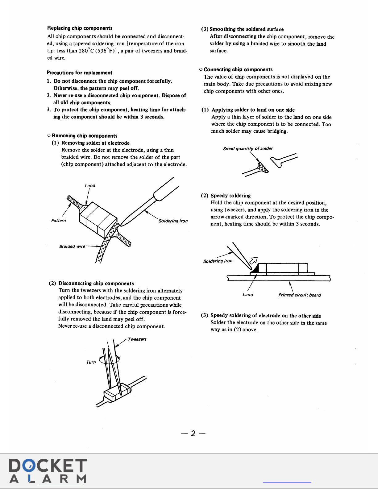
o Removing chip components
(l)
Removing solder at electrode
Remove the solder
at
the
electrode, using a thin
braided wire. Do not remove the solder
of
the part
(chip component) attached adjacent
to
the electrode.
Braided wire
(2) Disconnecting chip components
Turn the tweezers with
the
soldering iron alternately
applied
to
both
electrodes, and the chip component
will be disconnected. Take careful precautions while
disconnecting, because
if
the
chip component is forcefully removed the land may peel off.
Never re-use a disconnected chip component.
(3)
Smoothing the soldered surface
After disconnecting the chip component, remove the
solder
by
using a braided wire
to
sinooth
the
land
surface.
o Connecting chip components
The value
of
chip components
is
not
displayed
on
the
main body. Take due precautions to avoid mixing new
chip components with other ones.
( 1) Applying
s<>lder
to
land
on
one side
Apply a thin layer
of
solder
to
the land
on
one side
where
the
chip component
is
to
be connected. Too
much solder may cause bridging.
(2)
Speedy soldering
Hold the chip component at the desired position,
using tweezers, and apply the soldering iron in the
arrow-marked direction. To protect
the
chip compo-
nent,
heating time should be within 3 seconds.
~~~,~-------------
\
~
I
\
Land
Printed
circuit
board
(3) Speedy soldering
of
electrode
on
the other side
Solder
the
electrode on the other side in the same
way as in
(2)
above.
-2-
f
Find authenticated court documents without watermarks at docketalarm.com.
Exhibit 1010, Page 002
SECTION
1
MECHANICAL
OPELATION
MECHANICAL OPERATION
in
this
set
is
the
same
as
that
of
model WM-DD, so refer
to
WM-DD service
manual previously issued
for
MECHANICAL OPERA-
TION.
SECTION 2
DISASSEMBLY
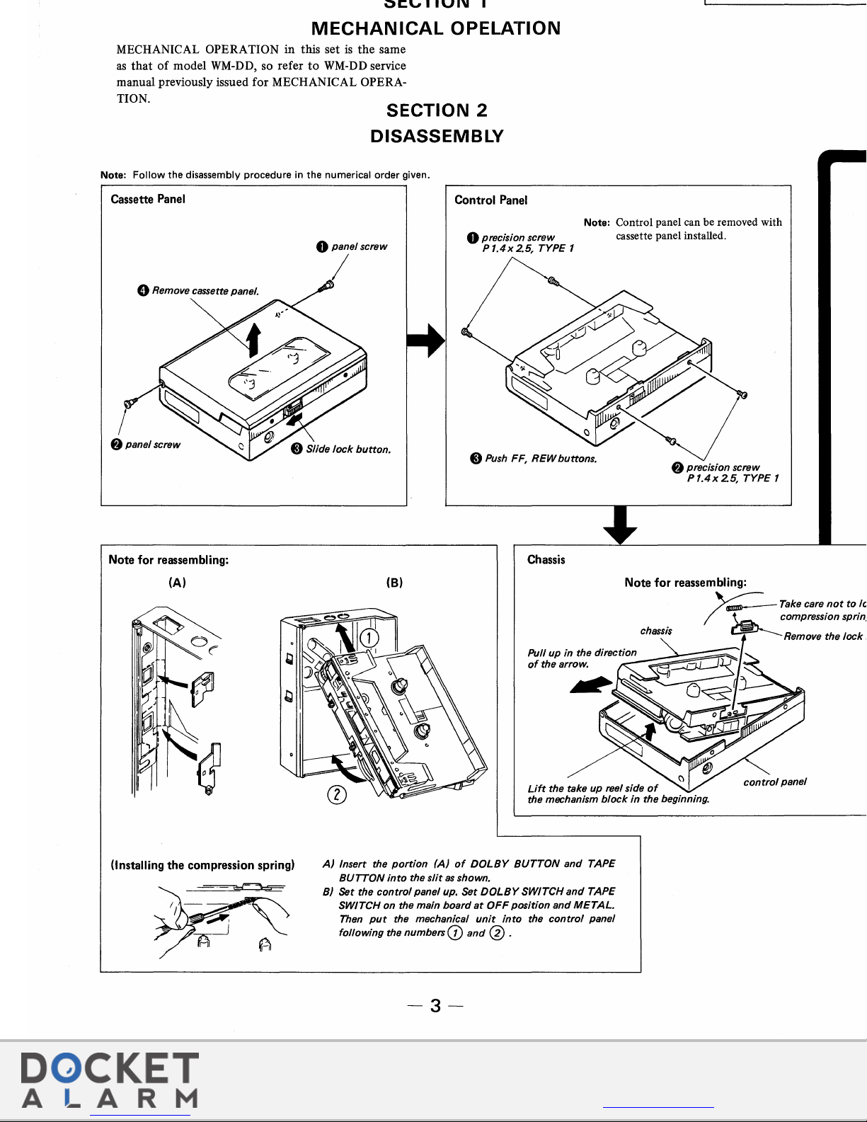
Note:
Follow
the
disassembly
procedure
in
the
numerical
order
given.
Cassette Panel
Control Panel
WM-DDm
0 panel screw
0 precision screw
Note:
Control panel can be removed with
cassette panel installed.
8 Remove cassette panel.
8 panel screw
Note
for
reassembling:
(A)
(Installing
the
compression spring)
P
1.4x
2.5, TYPE 1
I
8
Push
FF,
REW
buttons.
8 precision screw
P
1.4x
2.5, TYPE 1
Chassis
(B)
Lift
the take up reel side
of
control
panel
the mechanism
block
in
the beginning.
A)
Insert the
portion
(A)
of
DOLBY
BUTTON
and
TAPE
BUTTON
into
the
slit
as
shown.
B) Set the
control
panel up. Set
DOLBY
SWITCH
and
TAPE
SWITCH on the main board
at
OFF
position
and
METAL.
Then
put
the mechanical
unit
into
the
control
panel
following the
numbers(])
and
@ .
-3-
WM-DDm
Main B ard
f
Find authenticated court documents without watermarks at docketalarm.com.
WM-DDm
PRECAUTION
SECTION
3
ADJUSTMENTS
1. Clean
the
following
parts
with a denatured-
alcohol-moistened
swab:
playback
head
capstan
pinch
roller
2.
Demagnetize
the
playback
head
with a head
demagnetizer.
3.
Do
not
use a
magnetized
screwdriver
for
the
adjustments.
4.
After
the
adjustments,
apply
suitable
locking
compound
to
the
parts
adjusted.
5.
The
adjustments
should
be
performed
with
the
rated
power
supply
voltage unless
otherwise
noted.
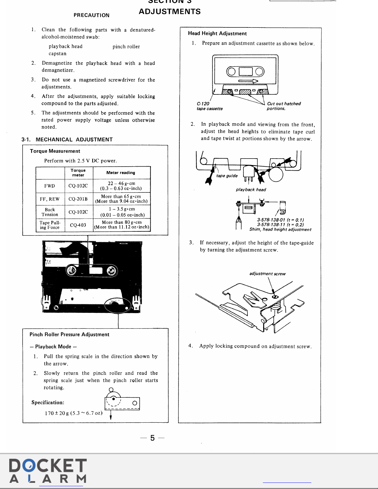
3-1. MECHANICAL ADJUSTMENT
Torque
Measurement
Perform
with
2.5 V DC
power.
Torque
Meter
reading
meter
22-46
g•cm
FWD
CQ-102C
(0.3-
0.63 oz•inch)
FF,
REW
CQ-201B
More than
65
g·cm
(More than 9.04 oz•inch)
Back
CQ-102C
1-
3.5 g•cm
Tension
(0.01-
0.05 oz•inch)
Tape Pull-
CQ-403
More than
80 g•cm
ing Force
(More than
11.12oz•inch)
Pinch Roller Pressure Adjustment
- Playback Mode -
1 . Pull
the
spring scale in
the
direction
shown
by
the
arrow.
2. Slowly
return
the
pinch
roller
and
read
the
spring scale
just
when
the
pinch
roller
starts
rotating.
p
S
'f'
, I • 1
pect
tcahon:
'~:.
-:._"~
__
-~
170 ± 20 g (5.3
"'6.7
oz)
-5-
Head Height Adjustment
1.
Prepare
an
adjustment
cassette
as
shown
below.
C-120
tape cassette
Cut
out
hatched
portions.
2. In
playback
mode
and
viewing
from
the
front,
adjust
the
head
heights
to
eliminate
tape
curl
and
tape
twist
at
portions
shown
by
the
arrow.
playback
head
~-A
~
T~
~
~~
3-578-138-01
(t
= 0.1)
3-578-138-11
(t
= 0.2)
Shim, head height
adjustment
3.
If
necessary,
adjust
the
height
of
the
tape-guide
by
turning
the
adjustment
screw.
adjustment
screw
4.
Apply
locking
compound
on
adjustment
screw.
f
Find authenticated court documents without watermarks at docketalarm.com.
Exhibit 1010, Page 004
 Loading...