

Sony Walkman SRF-S84 Service Manual
SRF-S84
SERVICE MANUAL
Ver 1.0 2002.02
SPECIFICATIONS
Frequency range
FM: 87.5-108 MHz
AM: 530 -1605kHz
Output
2 (stereo earphones) jack (Ø3.5mm stereo minijack) load impedance 16Ω
E Model
Australian Model
Chinese Model
Power output
3.6mW + 3.6mW (at 10% harmonic distortion)
Power requirements
1.5 V DC, one R03 (rize AAA)
Dimensions
Approx.39.5 × 78.5 × 16.5 mm (w / h / d)(Approx. 1
not incl. projecting parts and contorols
Mass Approx.
61.2g (2.16 oz) incl. abattery and stereo earphones
Accessories supplied
stereo earphones (1)
Design and specifications are subject to change without notice
9
/16 × 31/8 × 21/32 inches)
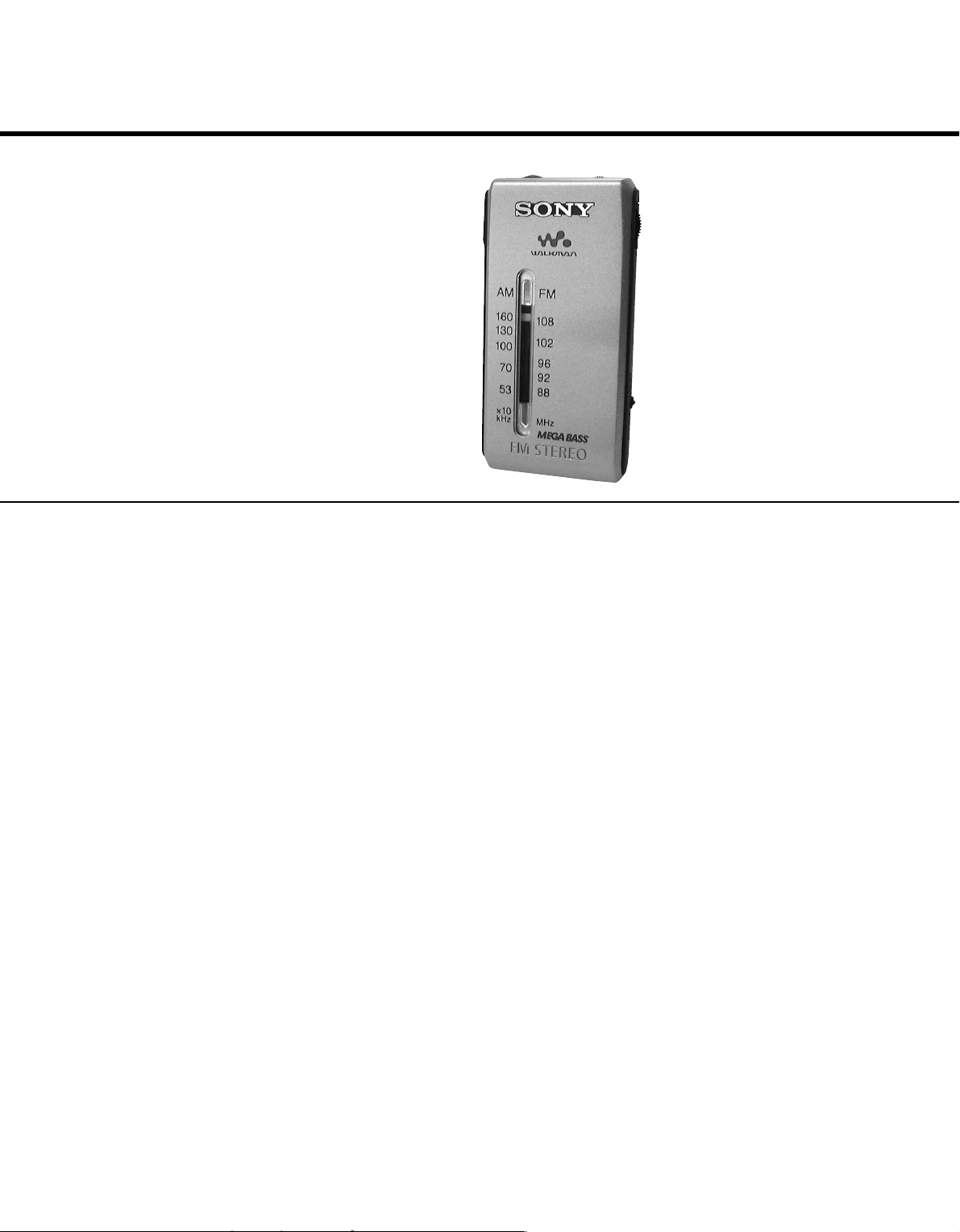
FM STEREO/AM RADIO
SRF-S84
TABLE OF CONTENTS
Specifications ...........................................................................
1. GENERAL
Location and Function of Controls ....................................
2. DISASSEMBLY
2-1. Cabinet (Rear).............................................................
2-2. Main Board ................................................................. 3
3. DIAL POINTER INSTALLATION
4. ADJUSTMENTS
5. DIAGRAMS
6. EXPLODED VIEW
.......................................................... 5
.................................................................... 6
.................................................. 10
7. ELECTRICAL PARTS LIST
........................... 4
.................................... 1
1
2
3
1
Flexible Circuit Board Repairing
• Keep the temperature of the soldering iron around 270°C during
repairing.
• Do not touch the soldering iron on the same conductor of the
circuit board (within 3 times).
• Be careful not to apply force on the conductor when soldering or
unsoldering.
Notes on chip component replacement
• Never reuse a disconnected chip component.
• Notice that the minus side of a tantalum capacitor may be damaged by heat.
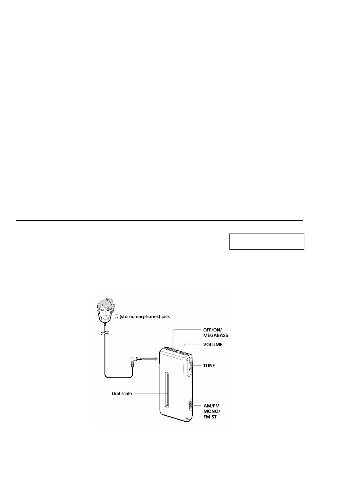
LOCATION AND FUNCTION OF CONTROLS
SECTION 1
GENERAL
This section is extracted from
instruction manual.
2
SECTION 2
)
SRF-S84
DISASSEMBL
r
The equipment can be removed using the following procedure.
Set
Note : Follow the disassembly procedure in the numerical order given.
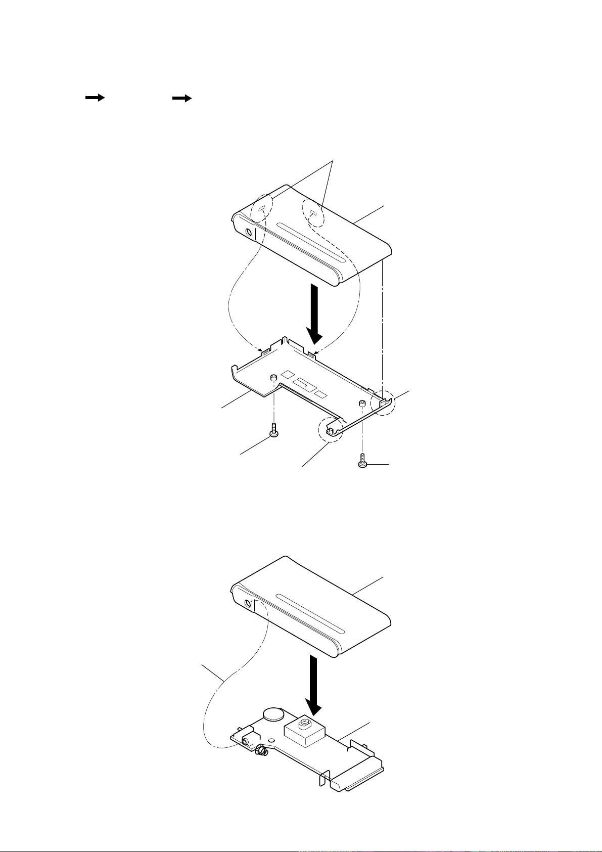
2-1. CABINET (REAR)
Cabinet (rear)
Main board
4
3
Y
Claws
Cabinet (front)
2-2. MAIN BOARD
Cabinet (rear)
4
Screw(B1.7 x 8)
1
2
Claw
1
2
Claw
Screw(B1.7 x 8)
Cabinet (front
2
Main board
3
SRF-S84
)
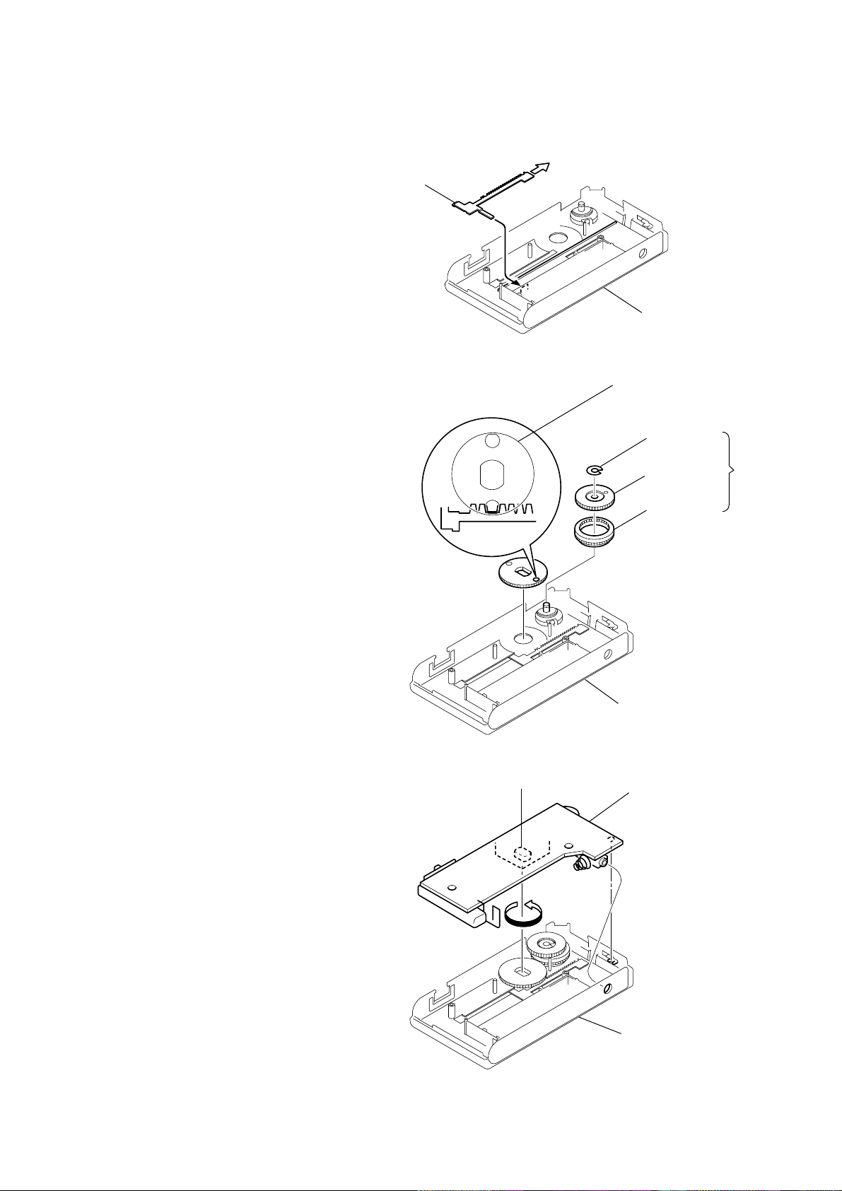
SECTION 3
DIAL POINTER INST
Note : Follow the installation procedure in the numerical order given.
1 Insert the pointer into the cabinet (rear).
2 Slide the pointer to arrow direction.
3 Install the gear (tuning capacitor), and engage with pointer as
a figure.
4 Install the gear (midway) and the knob (tuning), and fasten it
with washer.
ALLA
Pointer
1
TION
2
Cabinet (rear
Gear (tuning cpacitor)
Washer
Knob (tuning)
4
Turn the CV1 in a direction as a figure.
5
6 Install the main board.
Pointer
CV1
5
3
Gear (midw
Cabinet (rear)
6
Main board
ay)
Cabinet (rear)
4
SECTION 4
r
CT1 : FM Frequency Coverage Adjustment
CT4 : AM Frequency Coverage Adjustment
Q1
Q1
ADJUSTMENTS
SRF-S84
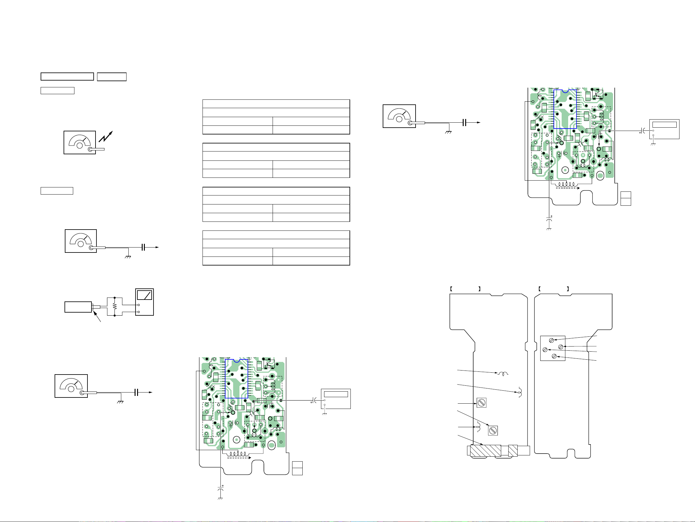
TUNER SECTION
AM Section
Band : AM
V
olume : MAX
AM RF signal
generator
30% amplitude modulation by 400Hz
signal.
Output level : as low as possible
FM Section
Band : FM
Volume : MAX
FM RF signal
generator
22.5: kHz frequency deviation by
400Hz signal
Output level : as low as possible
0dB = 1µV
Put the lead-wire
antenna close to
the set.
16 Ω
0.06 µF
level mete
TP6 (RF IN)
MAIN board
• Repeat the procedures in each adjustment several times, and the
frequency coverage and tracking adjustments should be finally
done by the trimmer capacitors.
AM FREQUENCY COVERAGE
ADJUSTMENT
Adjust for a maximum reading on level meter.
L3
CT4
AM TRACKING ADJUSTMENT
520kHz
1,650kHz
Adjust for a maximum reading on level meter.
L5
CT3
FM FREQUENCY COVERAGE
520kHz
1,650kHz
ADJUSTMENT
Adjust for a maximum reading on level meter.
L6
CT1
FM TRACKING ADJUSTMENT
86.5MHz
109.5MHz
Adjust for a maximum reading on level meter.
L1
CT2
86.5MHz
109.5MHz
2nd OSC Adjustment
Procedur
e :
FM RF signal
generator
Carrier frequency : 98MHz
Modulation : no modulation
Output level : 100dB µV(100mV)
0.01 µF
TP6 (RF IN)
MAIN board
1. Connect the frequency counter to TP10 as shown the figure.
2. Turn the set to 98MHz.
3. Adjust L2 for 57.1MHz reading on frequency counter.
Standard Value : 56.85 –57.35MHz
Adjustment Location :
Connect Location :
[MAIN BOARD] (SIDE B)
30
1
C20
C23
C21
R4
L6
-2
TP8
C18
S1
-1
10µF
MAIN BOARD (SIDE B)MAIN BOARD (SIDE A)
IC1
15
C22
C10
TP8
C19
L5
AM
FERRITE-ROD
ANTENNA
25
20
16
R11
L3
Frequency
C8
C12
C11
C3
C7
C9
TP10
TP9
L4
R3
TP10
C4
L2
counter
1µF
11
1-682-982-
(11)
set
+
–
Headphone jack (J1)
FM VCO Adjustment
Procedur
e :
FM RF signal
generator
Carrier frequency : 98MHz
Modulation : no modulation
Output level : 100dB µV(100mV)
0.01 µF
TP6 (RF IN)
MAIN board
1. Connect the frequency counter to TP9 as shown the figure.
2. Turn the set to 98MHz.
3. Adjust L4 for 38kHz reading on frequency counter.
Standard Value : 37.95 –38.05kHz
Connect Location :
[MAIN BOARD] (SIDE B)
30
1
C20
C23
L6
C18
C21
S1
-2
-1
R4
TP8
10µF
IC1
15
C22
C10
TP8
C19
L5
AM
FERRITE-ROD
ANTENNA
25
20
16
CT3: AM Tracking Adjustment
CT2 : FM Tracking Adjustment
R11
L3
Frequency
C8
C12
C11
C3
C7
C9
TP10
TP9
L4
R3
TP9
C4
L2
counter
1µF
L6: FM Frequency Coverage Adjustment
L3 : AM Frequency Coverage Adjustment
L1 : FM Tracking Adjustment
L4 : FM VCO Adjustment
L2: FM 2ND OSC Adjustment
L5 : AM Tracking Adjustment
11
1-682-982-
(11)
55
 Loading...